12. Output devices
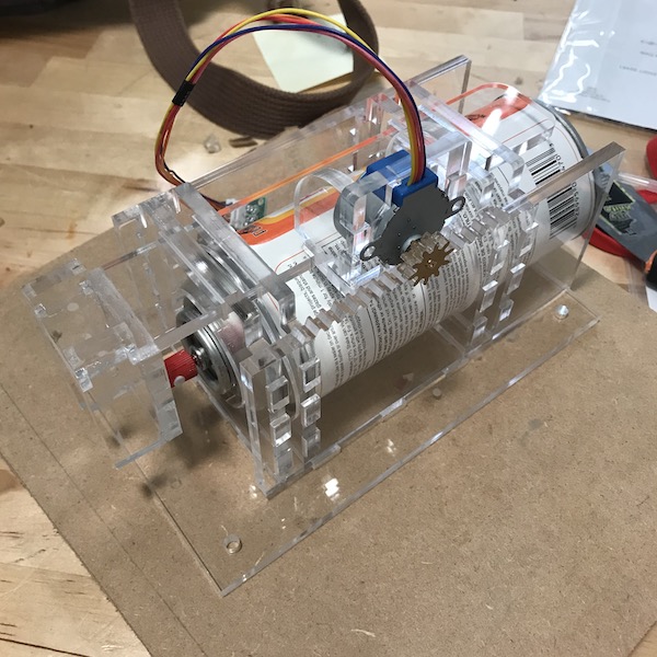
for my output device I set up the end effector for my final project. It is a spray paint can actuator running off a single stepper motor controlled by an attiny44 board.
construction of the can holder
I drew a simple parametric model of the can holder to be cut out of 1/4” plexiglass. The parameter table allows to adjust the size of the can and the thickness of the material. I had a lot of this material left over from making shields for retail stores. typically I would have chosen a less expensive material, but I wanted to do a bit more solvent welding practice and I had the stock necessary.
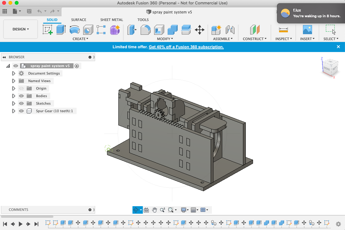
design of the rack and pinion
Working on Machine week was helpful for understanding how to draw gears. I used the gear generation script in fusion and modified it to fit onto my stepper. this took a couple of iterations to get the press fit snug. For the rack I isolated a single tooth from my gear and then copied it with the necessary spacing. This video was helpful though I took some shortcuts.
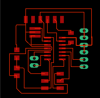
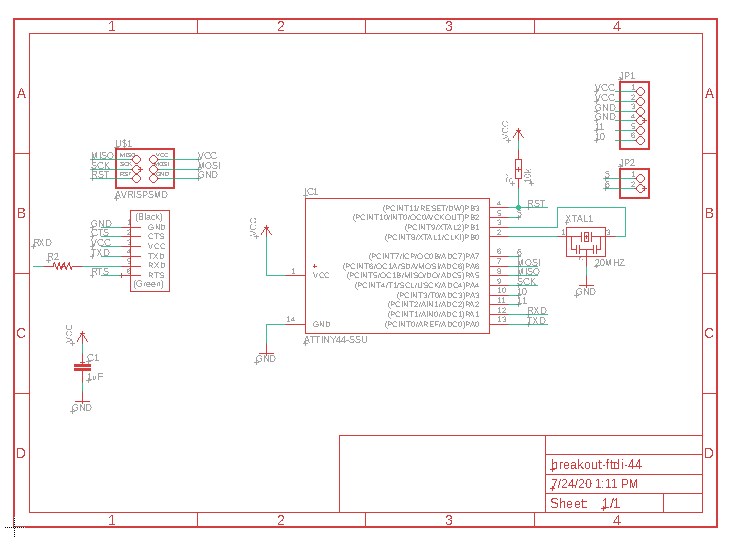
Board Design
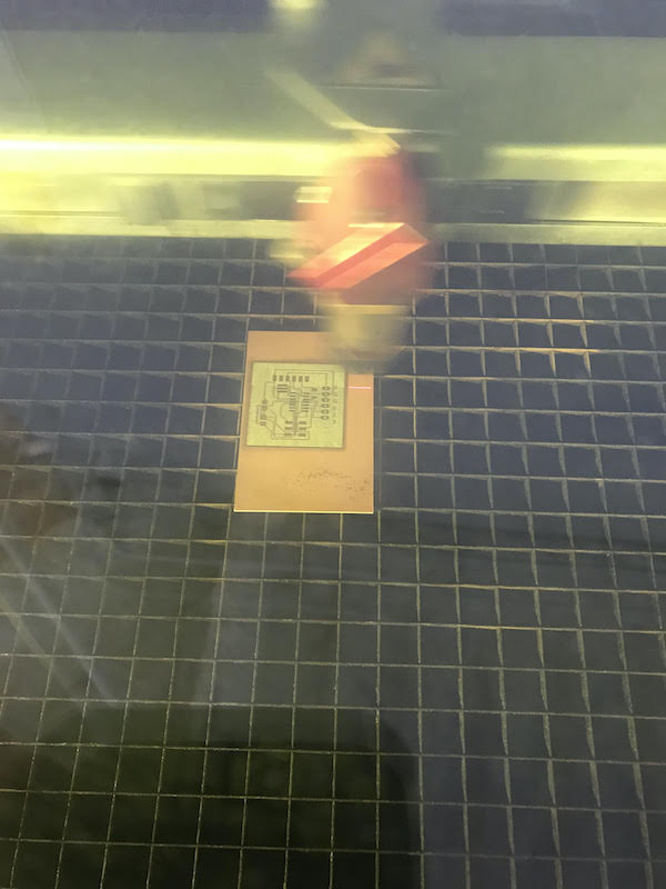
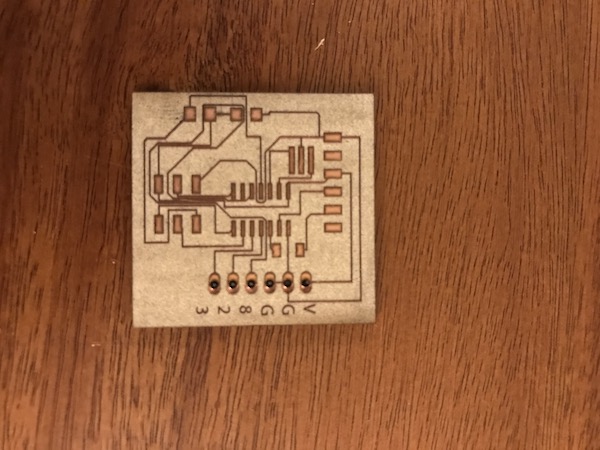
I design a breakout for an attiny44 to use for this project. Since it has very fine traces I fabricated it on the fiber laser.
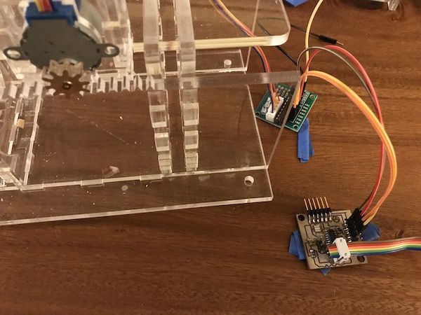
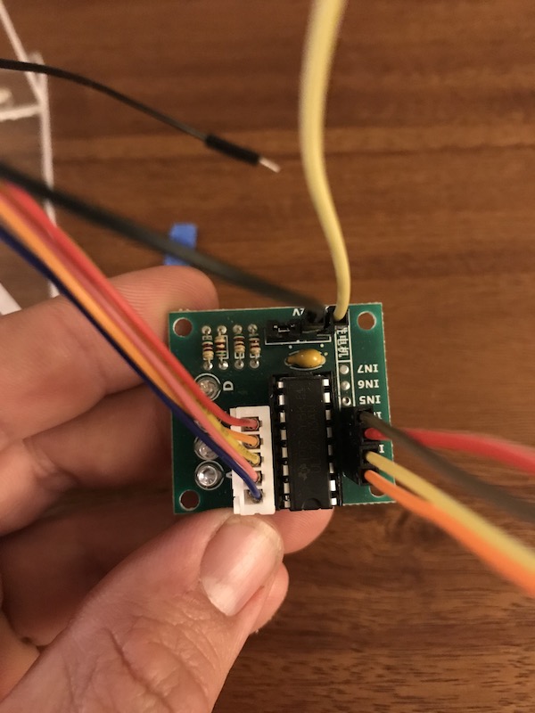
Motor Setup and Programming
The motor I used is a small stepper motor paired with a H-bridge controller. While the motor only needs 5 volts. It’s suggested from some tutorials I’ve read that it works best with a power line independent of the board. I’m currently running it off of a bench top power supply and the board is powered from my computer USB. Keeping the power management organized will be an important aspect of my final project.
With everything wired I started to test the motor with some simple programs for stepper motors. Most of these programs just pulse the motor back and forth. This gave me a sense of how much power the actuator will have. I may consider padding the pressure point with a spring to improve the actuation. As it stands currently the code will need to be adjusted to accommodate different size cans. A future iteration would be a simple button user interface to “jog” the pusher to the correct position.
The test code below is from this tutorial
/* Stepper Motor Control */

#include <Stepper.h>
const int stepsPerRevolution = 90;
// change this to fit the number of steps per revolution
// for your motor
// initialize the stepper library on pins 8 through 11:
Stepper myStepper(stepsPerRevolution, 8, 9, 10, 11);

void setup() {
   // set the speed at 60 rpm:
   myStepper.setSpeed(5);
   // initialize the serial port:
   Serial.begin(9600);
}

void loop() {
   // step one revolution in one direction:
   Serial.println("clockwise");
   myStepper.step(stepsPerRevolution);
   delay(500);
   // step one revolution in the other direction:
   Serial.println("counterclockwise");
   myStepper.step(-stepsPerRevolution);
   delay(500);
}
Design Files
video
Group Assignment
For the group assignment I measured the power consumption of a DC motor with a multimeter and a variable power supply.
I ‘Spliced’ the multimeter into the circuit between the ground of the motor and the ground of the power supply. I could then turn on the power supply and observe the amp draw on both the multimeter and the power supply. In this case they are almost the same! Which I would expect with a high quality power supply!
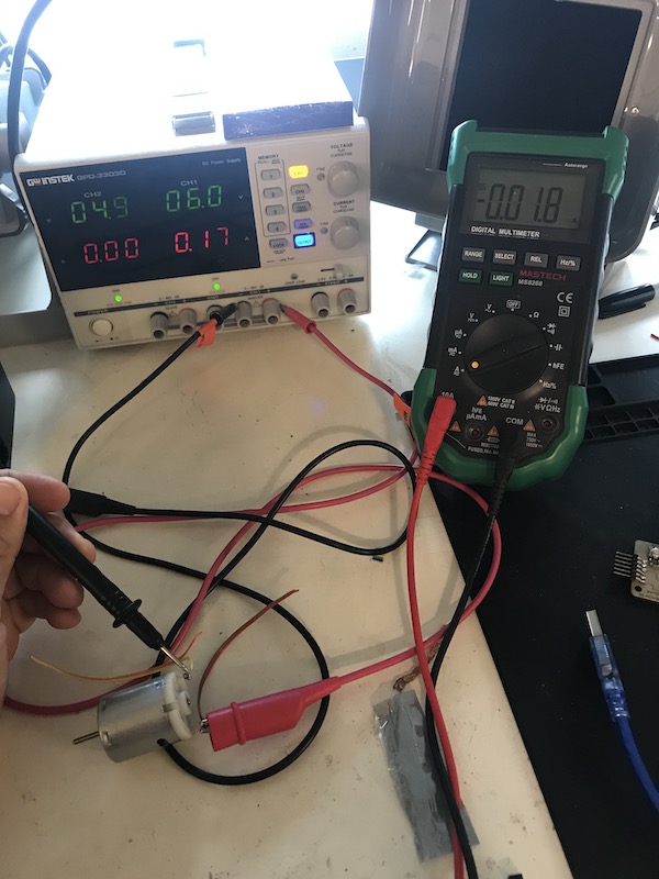
At 6Vdc the motor is drawing .18 amps. V*amps=watts so in the case the motor is consuming 1.08 watts of power running without a load.