Fab Academy 8

Embeded Programing

Mobirise

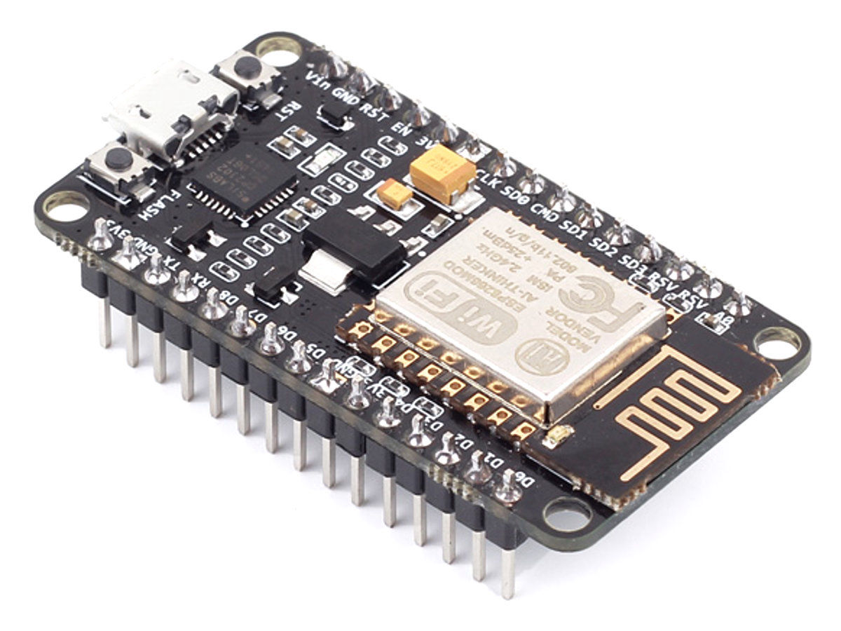
For this project I´m using a NodeMCU development boardwith an integrated ESP8266 chip that comes with integrated WIFi and Bluethoot module antena. From the datasheet, I will highlight some things that I find usefull to me (or that I understand).

• Integrated TCP/IP protocol stack

• Supports antenna diversity

• WiFi 2.4 GHz, support WPA/WPA2

• Support STA/AP/STA+AP operation modes

• Support Smart Link Function for both Android and iOS devices

• Operating temperature range -40C ~ 125C

• Dual and single antenna Bluetooth co-existence support with optional simultaneous receive (WiFi/Bluetooth) capability.
Mobirise

(Datasheet Abstract)

3.1.1. General Purpose Input/Output Interface (GPIO)

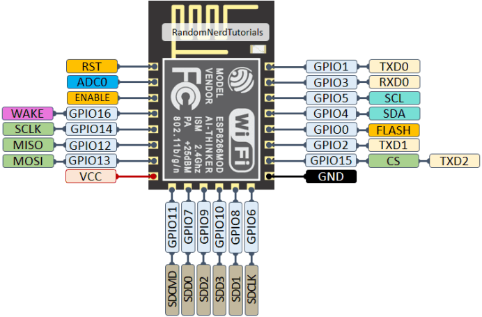
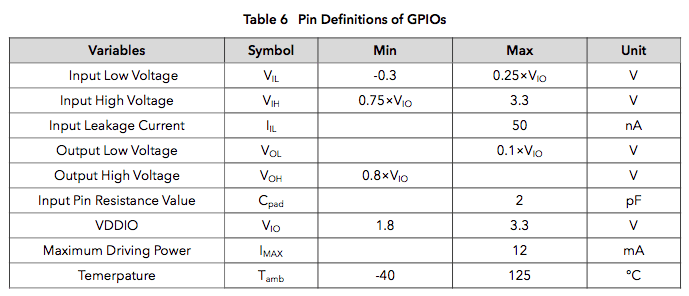
There are up to 17 GPIO pins. They can be assigned to various functions by the firmware. Each GPIO can be configured with internal pull-up (except XPD_DCDC, which is configured with internal pulldown), input available for sampling by a software register, input triggering an edge or level CPU interrupt, input triggering a level wakeup interrupt, open-drain or push-pull output driver, or output source from a software register, or a sigma-delta PWM DAC. These pins are multiplexed with other functions such as I2C, I2S, UART, PWM, IR Remote Control, etc. Data I/O soldering pad is bidirectional and tri-state that include data input and output controlling buffer. Besides, I/O can be set as a specific state and remains like this. For example, if you intend to lower the power consumption of the chip, all data input and output enable signals can be set as remaining low power state. You can transport some specific state into the I/O. When the I/O is not powered by external circuits, the I/O will remain to be the state that it was used the last time. Some positive feedback is generated by the state-remaining function of the pins, therefore, if the external driving power must be stronger than the positive feedback. Even so, the driving power that is needed is within 5uA.


ESP8266 Pinset

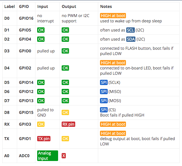
BEST PINS TO USE

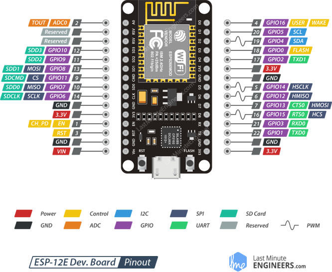
ESP8266 12-E Chip Pinout

The ESP12-E NodeMCU Kit is one of the most used ESP8266 development boards. It features 4MB of flash memory, access to 11 GPIO pins, and one analog-to-digital converter (ADC) pin with 10 bit resolution. The board has a built-in voltage regulator and you can power up the module using the mini USB socket or the Vin pin.

Uploading code to the board is as easy as uploading code to the Arduino, there’s no need for an FTDI programmer, as it comes with a usb-to-serial converter built-in.

This is the board we use more often in our Wi-Fi and IoT projects. It is very versatile and it’s great for beginners. So, if this is your first time with the ESP8266, this module is a great choice. Take a look at the links below to find out the ESP8266 12-E NodeMCU kit on your favorite store.
NOTE:
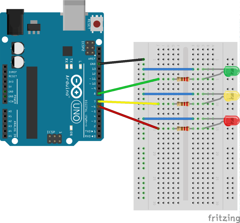
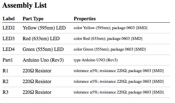
This is the schematics and the BOM I used for both projects, but since Fritzing doesn´t has NodeMCU in the library, I used a Arduino UNO to show it.

LED BLINK (PlatformIO)

To make the LED BLINK, I started with the basic arduino blink predefined code and the modified it so it makes 3 leds blink with different timings, reducing the time each time untill they all turn on at the same time.

I first did it in the Arduino IDE, but I´m going to show the process in PlatformIO, and with the NodeMCU instead of the Arduino UNO.

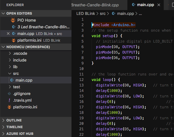
At the begining I didn´t know where exactly to write the code, because the software opens in the platformio.ini file, which looks like a normal code file, but it seems to be the main initialization file, but then I sicovered that you have to writte it in the main.ccp file, which actualy you can rename as you wish.

INITIAL CODE:     Arduino Blink Integrated Code.

ESP8266 12-E Chip Pinout

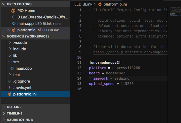
platform.ini

In that platformio.ini you have to declare the enviroment, the platform, the board and the framework like this:

    [env:nodemcuv2]
    platform = espressif8266
    board = nodemcuv2
    framework = arduino


The software does it automaticaly when you create a new project and define this settings, but if you are going to add some addition external libraries you will also have to declare them here, I´ll explain a bout this in the Breathe example.
ESP8266 12-E Chip Pinout

Include Arduino Library:

Another important thing is that if you want to code it with the same arduino language, you have to call the Arduino library in the beggining of the code:

    #include <Arduino.h>

If you don´t call the library, it won´t recognize a lot of things in your code like Delay, Output, PinMode, etc.

Another thing that might be confusing between the Uno and the NodeMCU, is how they call the pins in the code, because they have three diferent numbers: GPIO(#), The reserved number in grey and a diferent number drawn on the board with a letter. So the number you should use is the number on the board with the letter. So in my case it would be        

    D8 (16 - GPIO15)

    D6 (6 - GPIO12) 

     D5 (5 - GPIO14)

3 LED
MILLIS BLINK (PlatformIO)

Blinking a LED with Millis, gives you the benefit of not making the chip processor using a Delay code and eaiting for it to happen, but instead he sets a star of LOw or HIGH to the led, deppending on a time you assign. This means that te codeo will check the clock agin in each loop, and when is the same than the time you coded, then the LED will change.

Basicly it says: If the LED is ON, and the Current Time, minus the Starting Time (0) is bigger or equal to the designed OnTime, then turn LED OFF, and reset the current time to be 0. And the proces starts again but now to turn it off with the designated time you choose.

          if((ledState == HIGH) && (currentMillis - previousMillis >= OnTime))
          {
            ledState = LOW; // Turn it off
            previousMillis = currentMillis; // Remember the time
            digitalWrite(ledPin, ledState); // Update the actual LED
          }
          else if ((ledState == LOW) && (currentMillis - previousMillis >= OffTime))
          {
            ledState = HIGH; // turn it on
            previousMillis = currentMillis; // Remember the time
            digitalWrite(ledPin, ledState); // Update the actual LED
          }

The tutotial goes untill lighting 2 leds with millis, yo I changed the code to work with a third led and added it.


3 LED BREATHE, FADE, BLINK (PlatformIO)

To make the LED BREATH assignment, I followed some of the instructions of the Jled Library from the GitLab repo, and after trying the different combinations (Candle, Blink, Static, Breath, Fade, etc). The ones I liked most where the ones with multiple leds, so I keept my conection with 3 leds, and used the multiles.ino code and modified it a bit. This one mixes the Breath, Fade and Blink codes in one. It also uses the internal led as a fourth led.

ADDING THE LIBRARY:
Since we are using a library that is not part of the arduino, we need to add jled to our library dependencies in our platformio.ini project file like this:

        [env:nodemcuv2]
        platform = espressif8266
        board = nodemcuv2
        framework = arduino
        lib_deps = jled

This is needed for the líbrary to load when you call it in your CCP code file.

PMW PINS:
Another important thing I realized, is that the breath effect and others, only work in PWM (Pulse Width Modulation) pins, which in case of the NodeMCU are D2, D5, D6 and D8. I have read that through software, you can also convert all the digital pins into PWM, but I´m not sure how to do it yet. This was interesting to me, because I have never understood what that really means untill now, and I also discovered that in the pinnout graphics they usually paint it with an ondulated line. I also dicovered that the UNO has painted lines near the numers in the PWM pins. I´m going to copy the Wikipedia description, just to remind in the future what they are.

        Pulse-width modulation:
        Pulse width modulation, or pulse-duration modulation, is a method of         reducing the average         power delivered by an electrical signal, by         effectively chopping it up into discrete parts. The         average value of         voltage fed to the load is controlled by turning the switch between supply         and load on and off at a fast rate.

This JLED Library was really usefull to do nicer things with less code, I could even do the same I did with the blinks, but with much less code.


Flashing MicroPython with RaspberryPi3

Another thing that was interesting to me was to be able to Flash the NodeMCU with Micropython with a RasperryPI3 thourgh terminal, but I think I´ll document that in networks.


pip install esptool

esptool.py --port /dev/ttyUSB0 erase_flash

esptool.py --port /dev/ttyUSB0 --baud 460800 write_flash -- flash_size=detect 0 esp8266-20170108-v1.8.7.bin (this correspondes to the version you donwloaded)

esptool.py --port /dev/ttyUSB0 --baud 460800 write_flash --flash_size=detect -fm dio 0 esp8266-20170108-v1.8.7.bin (this correspondes to the version you donwloaded)

Voltio

Mobirise web page maker - Go now