Output Devices
I did this week without lab access due to CoVid lockdown restrictions.
Page Summary
- Measuring power consumption of output devices.
- Output - Motor
- Adding an input sensor
- Designing a pcb for outputs
- References
- Design + Code files
1. Measuring power consumption of output devices.
I use a USB power meter to measure the power consumption of a LED strip using a ESP8266 module. It is a very convenient way to detect power abnormalities.

When the ESP8266 is connected through the USB port without any output devices, it shows a power 0.408 W.

Then I connected a LED strip with 3 wires - GND, 5V and a digital pin. It showed a power reading of 1.828 W.

I also changed the VCC from 5V to 3.3V and check the power.

Power now showed 1.119 W.

I then connected a small DC motor, and the power was 2.788 W!

I connected a different bigger DC motor, but surprisingly it used a lot lesser power - 0.765 W. I’m not sure how exactly different the two motors are.

2. Output - Motor
This week I used an Arduino Uno to make a forever spin top spin at different speeds and directions.
I used the Zeotrope tutorial from the Arduino starter kit as it had a similar function.
These are the components I need to control the motor:
* DC motor - only motor I have available now
* H-bridge - IC to control the direction change of the motor
* Potentiometer - to control speed manual input
* Switches - 1 for on/off, 1 for direction change
* Resistors - 10k ohm in series with switches
* Battery 9V - power with connector
* Arduino Uno + Breadboard + Jumper Wires

I referred to this schematic in the Arduino Projects book:

To understand the circuit I arranged everything and marked the functions and connections of each part. And checked the datasheet for H-bridge L298N.

From the above setup, we can see that the pins used are:
Digital Pins :
- 4 for on/off
- 5 for direction change
- 2 for motor control
- 3 for motor control
Analog Pins :
- A0 for speed control
Based on this I defined the constants in the sketch in Arduino IDE.
Then, defined the variables, defined inputs and outputs, setup code, and the loop. Each part is explained briefly in the
sketch.

I uploaded the sketch without any errors, but still the motor did not run. I checked all connections and finally had to change my battery.
Next, I fabricated a circular base to make the top spin on top from some tape and board I had at home. The pink top was milled by me on a Roland 4-axis milling machine some years back. If in the lab, I would like to make this setup more refined using the machines.

Finally I put everything together and this is the setup for a forever spinning top.
You can find the final Sketch at the end of this page.
3. Adding an input sensor
In my arduino kit I had 2 sensors, a temperature sensor and a tilt sensor, I used the latter to make the top spin.
A tilt sensor has a tiny ball inside that connects the legs to complete the circuit, on tilting, the ball loses contact with one leg and breaks the circuit.
First I made a simple tilt sensor test with led outputs to understand how it works. This was fairly simple. I used this tutorial to make leds light on tilting.

Next, I simplified the DC motor circuit from before by removing the H-brige, the potentiometer and the 2 switches, as I didn’t need to change direction or speed.
I referred this tutorial for different ways to use the dc motor. And then did something similar to this.
After I got that to work, I combined both sketches to make the tilt sensor the input and the motor the output.

I assembled all components, combining both the circuits

I made some changes to the base, as it was wobbly, and then assembled eveything.


This is the whole setup.

This is a video of it in action.
I would like to make the base more refined and add the breadboard and arduino inside, and connect to a battery instead of powering it from the arduino. To make the top spinner.
4. Designing a pcb for outputs
For my final project, the Aeroborator, I want to use a water pump, LED grow lights and a screen to display parameters. So I start designing using the pinouts for these individual outputs.
Outputs are:
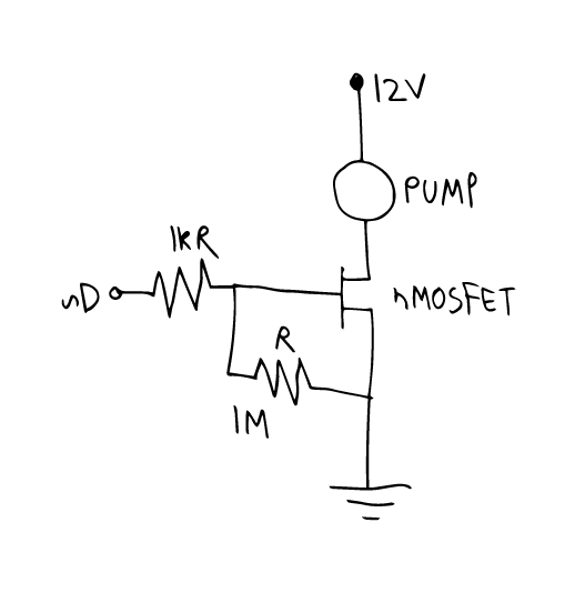
A 12V DC water pump is connected to the MCU with a n-channel MOSFET so I can control the flow of water using Pulse Width Modulation.
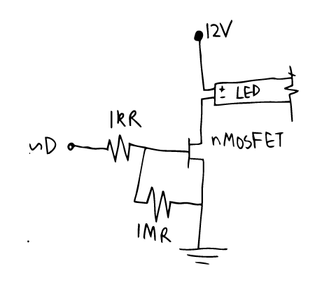
Similarly the 12V DC LED growlight strip with 3:1 RB 5050SMD LEDs is connected to the MCU with a n-channel MOSFET so I can control the light intensity. These come in different ratios of red-blue lights. I plan to use one with 3:1 meant for leafy plants.
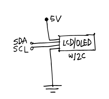
I use an OLED SSD1306 with I2C to make serial communication easier and use less pins on the MCU, only SDA and SCL.
So I use KiCAD to make the schematic. The inputs and power requirements can be found on the Project Development page.

After making the traces in the pcbnew section, I exported the svg, opened it in Ai and here are the traces and outline:


I made the pcb according to the workflow described in electronics production week and tested it and programmed it.

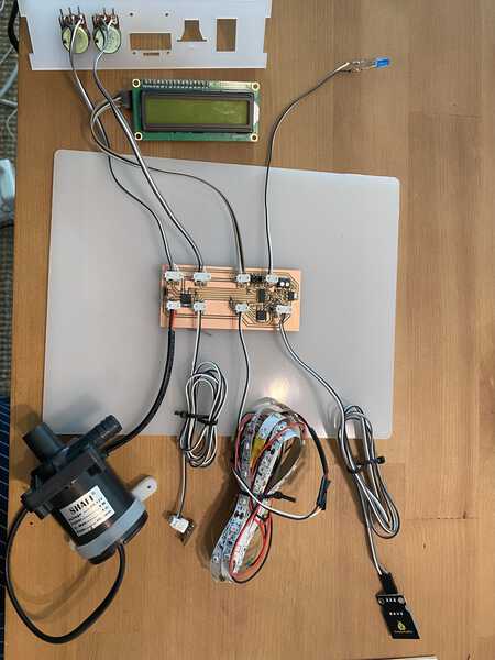
Here is a picture of all outputs with some additional inputs included.
You can find all design files and the code at the end of the page.
5. References
6. Design + Code files
Only DC motor - sketch
Only tilt sensor - sketch
Tilt sensor + DC motor - sketch
attiny + pump + lcd + led strip - KiCAD files
- schematic
- traces png
- outline png
- traces rml
- outline rml