3D Scanning and printing
This week I made some 3d printed tools and 3d scanned using photogrammetry.
Page Summary
- Introduction
- Testing Design rules
- Designing for 3D printing
- 3D models
- Creating toolpaths
- Printing
- References
- Photogrammetry
- 3D Scanning
- Design files
0. Introduction
3D printing is an additive form of manufacturing. It has a lot of advantages and disadvantages, by my understanding throughout this week, I have listed some below. Like Neil says, 3D printers are to FabLabs, what microwaves are to kitchens. They can do some parts but not replace all of manufacturing.
First advantage is that waste is minimised, because you use only the material that is required in the final product.
It is ideal for rapid prototyping, as it can make complex geometries that you traditionally need more than one processes to make. It is good for custom and small-scale mass customization production processes, but not necessarily for mass manufacturing. It also doesn’t have the best accuracy and tolerances, so not ideal for applications where precision is important. But it is fast, user-friendly and therefore very accessible.
The most widely used technology for 3D printing is Fusion Deposition Modelling (FDM). I will use FDM printers this week. There is also SLA, Stereolithography and Powder Bed Printing 3DP.
This hubs.com knowledge base has very good information about the subject. Also this BCN local documentation.
1. Testing Design rules
I used these files on thingiverse to test design rules of the Ultimaker 3 I used in the lab.
These test geometries are designed to evaluate specific performance characteristics and motion systems in common low-cost FDM/FFF machines. Make Magazine’s third annual 3D Printing Shootout was conducted using these files, created by Andreas Bastian to benchmark performance of desktop 3D printers.
These tests individually help with testing:
1. Dimensional Accuracy
2. Bridging Performance
3. Overhang Performance
4. Negative Space Tolerance
5. Fine Positive Features Performance
6. XY Resonance
7. Z Resonance
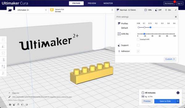
I use Cura to make the gcode. The tests are supposed to be evaluated at default ‘normal’ settings in PLA with a 0.4mm nozzle.
Layer Height: 0.15
Infill: 18%
Adhesion: On
Support: Off
After downloading the files, I sliced them one by one like so:
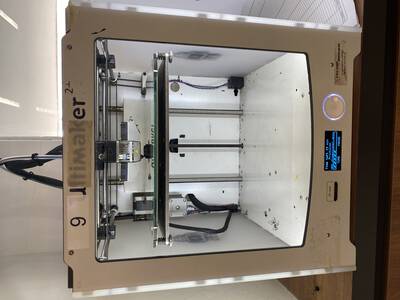
I used an Ultimaker 2+ to print the prints in FabLab SP.
There is a nice evaluation system described in How to evaluate the test geometries. It assigns a score by observing details to evaluate the different qualities of the machine. I think it is an interesting way to determine and learn how to design well for a particular machine. I used this to score the printer I was using. This is the result.
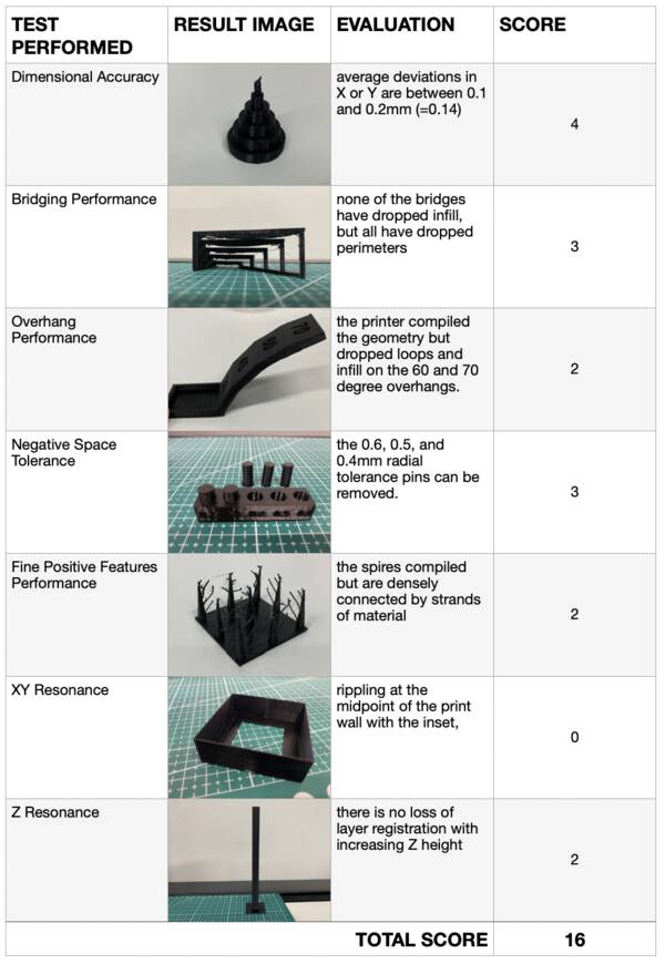
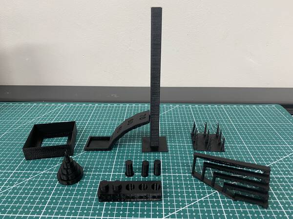
Here are all the tests overall:
It means that if I keep overhand till 50 deg, negative Tolerance atleast 0.4mm, not keep too fine details the qulaity of the design printing should be fine.
2. Designing for 3D printing
I wanted to make simple tools this weeks, so I experimented with simple joint mechanisms. Some references that I used to develop my designs:
- Compliant Mechanisms Research (CMR by BYU)
- Why machines that bend are better
- Compliant mechanisms by Devin Montes - video
- These transformed chopsticks
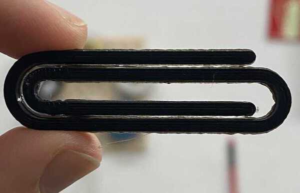
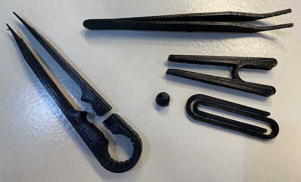
I first made a scaled-up version of a simple Gemclip and some other simple geometry clips. I bent one end to add a dimension, that does not allow it to be made using only one subtractive method.
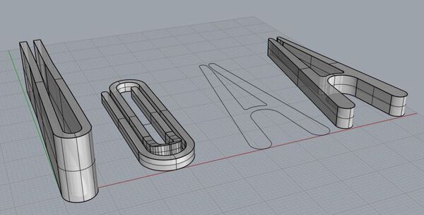
I first made it in 2D in plan to the size and proportion I wanted, and then extruded it in Z. Later I bent the inner part so that the model could be made subtractively easily, as now it had an undercut.
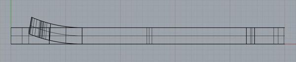
Then I used some parts of these tranformed chopsticks reference above that I found
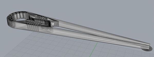
And then made normal tweezers and then modified the geomtry to make it compliant like the chopsticks above.
3. 3D models
Next after, watching some videos on making compliant mechanisms, I made a simple pick-and-place plier to test out the bending.
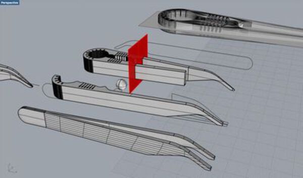
Some tweezers we used for holding down electronic components:
I wondered if it was easier to use the tweezers with a reversed action, where applying force releases the object. And by default it holds the object. For this, I used this mechanism designed by Devin Montes - video and transformed it for the tweezers.
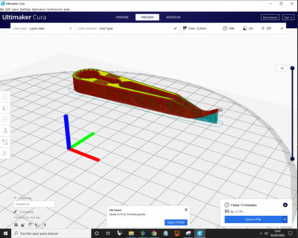
4. Creating toolpaths
I used Cura to make toolpaths for my 3d prints. I uploaded my stl files, set my machine, choose PLA as my material and used these settings:
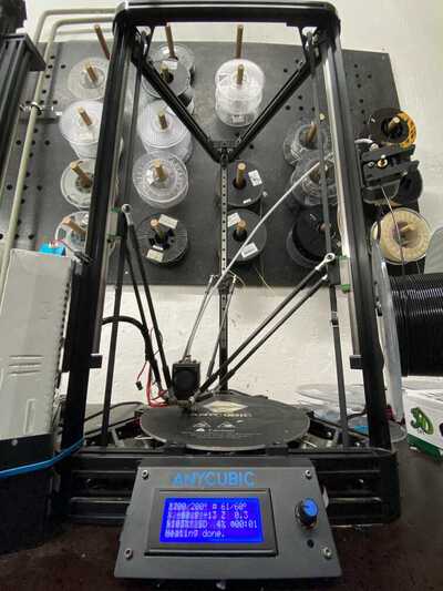
5. Printing
I used an Anycubic Kossel Plus 3D printer to print with a black 1.75mm PLA filament.
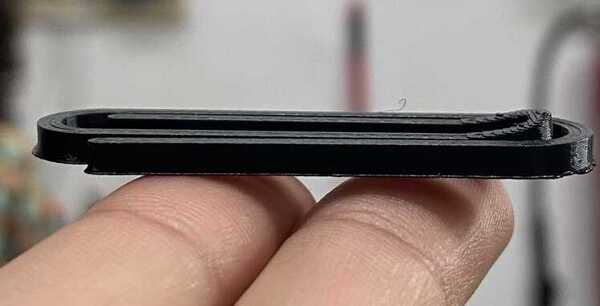
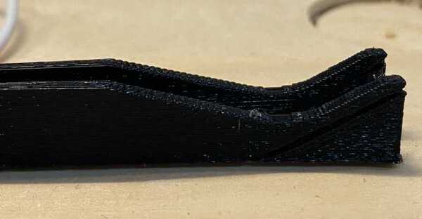
Printing the gemclip: The finish was alright, as the first layer spread a little too much, causing it to be broader then the actual form. The first layer has a layer height of 0.3mm, and all the consecutive ones were 0.15mm. I used a cutting blade to finish these edges.
In the next print, I used the same layer height for all layers. I printed a simple pick and place plier using a bent compliant joint.
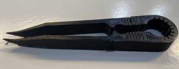
Simple nose-end tweezers:
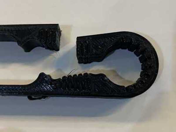
Used the transformed chopstick geometry, modified it for the tweezers:
The bending details were too small, they broke while I was trying to clean them up.
Overall, I made some small experiments with simple tools. I hope to remake the tweezer with the semi-compliant mechanism again after modifying the design.
If I can have more time on the machines I can modify the mechanisms by trying out various different tollerences, size and setting. And maybe make a small set of complaint mechanism tools.
- References
Design for 3d printing tutorials
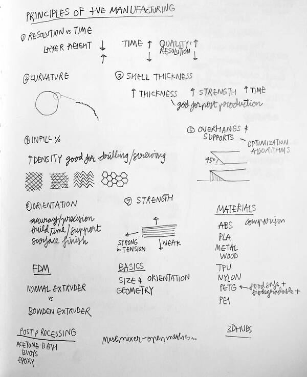
Here are some notes on principles of additive manufacturing.
- Photogrammetry
I used Agisoft Metashape to make a pointcloud. I followed this tutorial by Agisoft.
I clicked 53 images of the object on a plain background from all around. Steps to make a pointcloud:
- Workflow > Add photos
- Workflow > Align Photos (this step take some time depending on the number of key point limit and tie point limit you set.)
- Some photos failed to align, but I got 9003 points
- Workflow > Build dense cloud - medium quality.
- Workflow > Build Mesh
- Workflow > Build textures
The process: 
The output:
- 3D Scanning
I used a Roland Modela MDX-20 to scan the same object. I used the step-by-step manual for this.
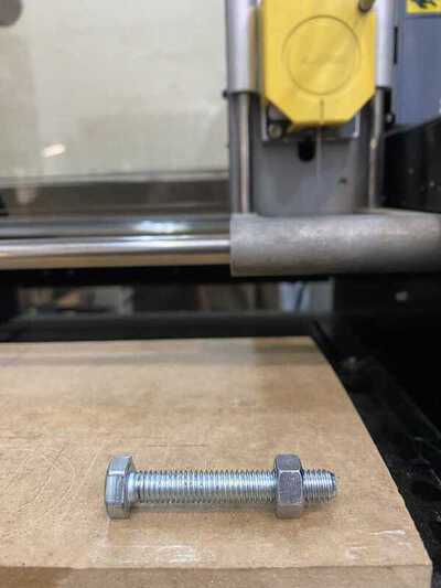
Stuck the bolt and nut using a double sided tape on the raised level bed.
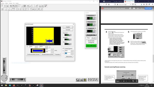 I set the scanning area, as close to the object as possible. And a scanning grid of 0.5mm on both X and Y axes.
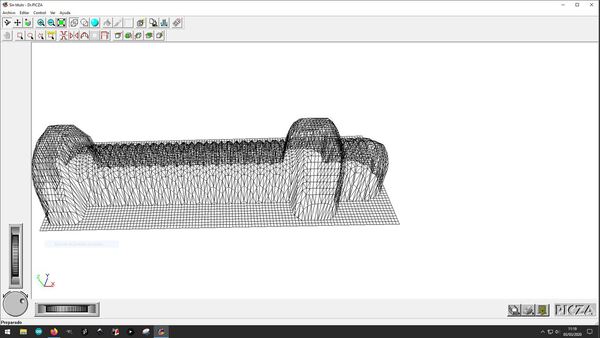
The output:
- Design files
All 3D models for printing
Probe scan of a lump of clay
Photogammetry of nut and bolt
Probe scan of nut and bolt
These transformed chopsticks