Computer controlled cutting
This week I worked on designing parametrically for laser cutting. Also, tried out cutting small things on the vinyl cutter.
Laser cutting
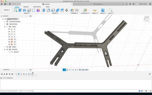
Designing the construction kit
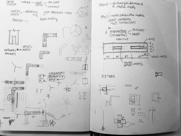
I sketched out a simple module so all dimensions were a multiple of the either the:
- Thickness of material
- Kerf
I wanted to keep the module itself simple so that it would:
- Use less material
- Provide multiple ways of assembly
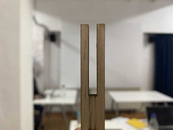
So I sketched out frame modules with notches at the ends for connections.
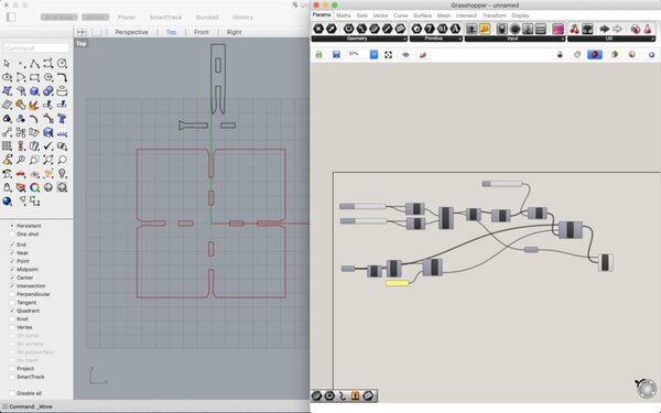
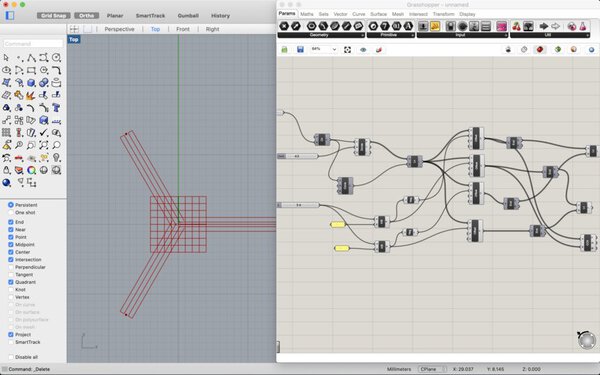
The script
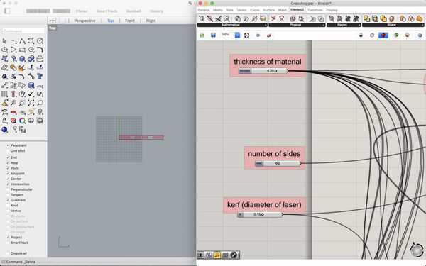
After various attempts in rhino+grasshopper and fusion360, I found a tutorial on notching. I tried that out, modified it to work for my module idea, and then ended up with a file where you could modify:
- Thickness of Material
- Kerf of laser
- Number of arms on the module
- Type of notch - press-fit, chamfer, or snap-fit
You can find the script at the bottom of this page.
Some attempted scripts that didn’t work as a whole:
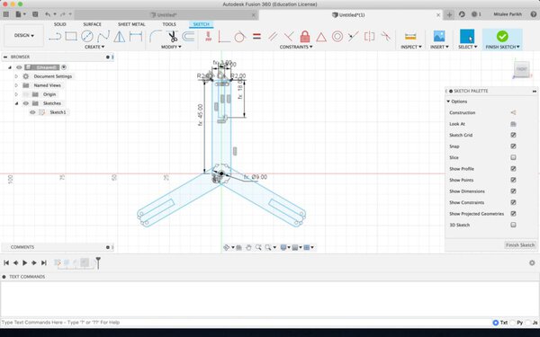
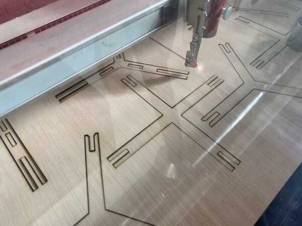
The machine
We could use one of three laser cutters at FabLabBCN. I started with the smallest Trotec Speedy 100 this week. It has a bed size of 610mm x 305mm and power of 12-60W. It is good for cutting paper, cardboard, MDF, plywood, acrylic.
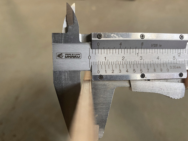
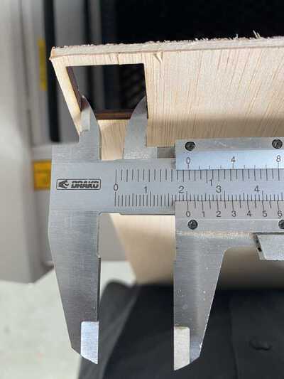
Material dimensions
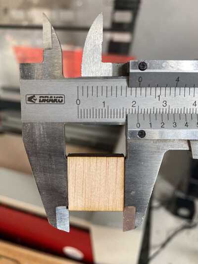
First I cut out a ply of 300mm by 600mm out of a big sheet. Using a vernier calliper I measured the thickness of the material in several places.
Setting focus
The focus of the machine can be set by adjusting the distance of the Z axis of the bed from the material’s top surface. We have a small probe at the lab, an attachment that you hang on the side of the laser nozzle. You manually move the bed up and when the probe touches the material, it falls off. This position sets the z-axis of the machine.
Measuring kerf
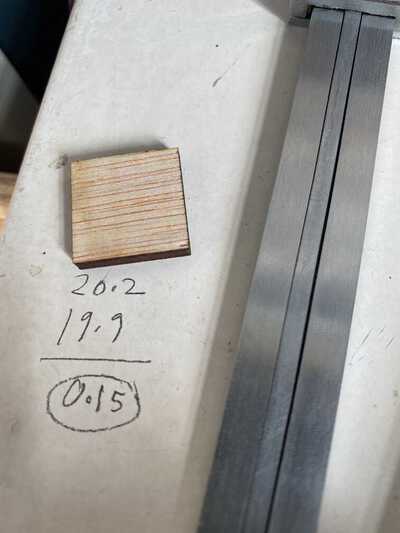
First, I cut a small square of 20mm x 20mm to check:
- Power and speed settings - I used the cutting guide to set the power to 75% and speed to 0.5mm/s for cutting.
- Kerf - After measuring the outside dimension of the square itself and the inside dimension of the negative left in the sheet, I divided the difference by 2 and found the kerf of the machine to be 0.15mm.
Add to parametric file
Now that I had found my 2 parameters : thickness=4.35mm and kerf=0.15mm, I adjusted the sliders on my gh script.
Bake model
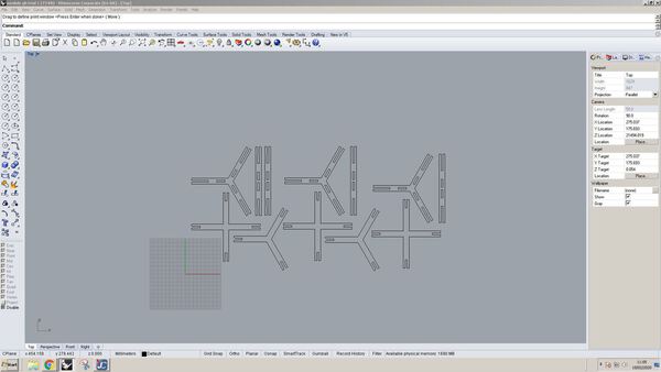
I tried multiple different combinations of the number of module arms, and the type of notches to test everything and baked them separately. I adjusted them manually in Rhino to fit inside 300mm by 600mm. I put them in a the same layer in black for cutting.
Here is the Rhino file.
Set cutting parameters
Checked for no duplicate and all flat lines, and set material parameters.
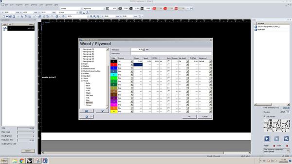
The settings I used for cutting are:
Speed: 0.5mm/s
Power: 75%
Thickness of Material=4.35mm
Kerf=0.15mm
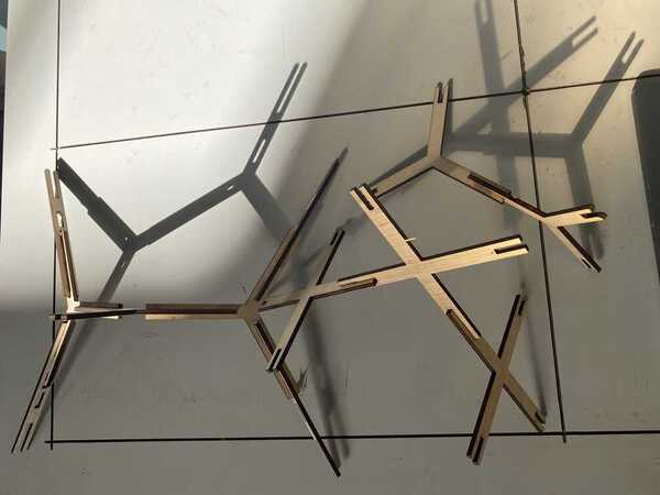
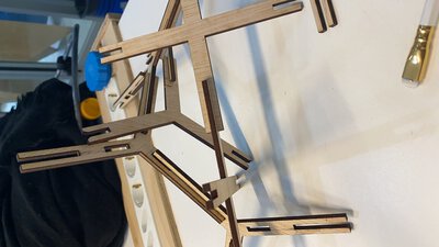
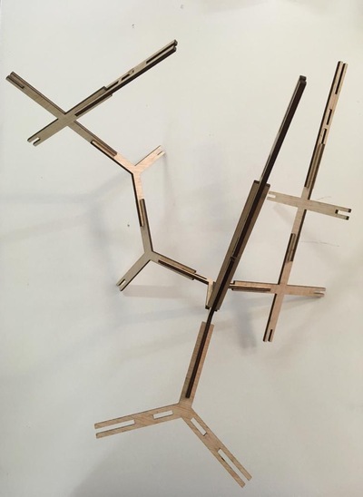
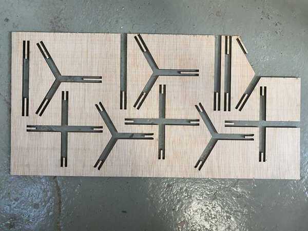
Assembly
The pieces came out neat using the cutting settings. 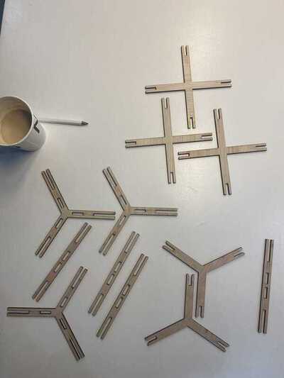
Here are pictures of different assemblies:
For next time:
- Cut inside parts first, because the piece shifted when it cut the outside first. Put them in a separate layer.
- Since ply is a little warped - put the material concave side up to allow sticking the edges to the bed.
- Lots of material wasted in the sheet - use nesting software/plug-in to optimise curves.
- Modules too big and long - modify some multiples of thickness in script and make them shorter.
- The snapping part of the snap-fit notch was too small (equal to the kerf) - modify the script to make it bigger.
Design Files
Final files: The rhino notch file used with this grasshopper script
All failed Fusion files
All grasshopper script attemps
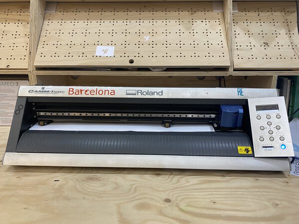
Vinyl cutting
I used a Roland Camm-1 in our lab to cut some white vinyl stickers.
Designing a vector sketched
I made two sketches, one an axonometric cube stack and the other a some letters. I cut some simple curves that I made on Adobe Illustrator. I made them with the line tool. Gave some thickness to the lines. Made path outlines and then did a boolean union on pathfinder tools to make single outlines. The figure on the left is outlines, the one on the right is just paths. 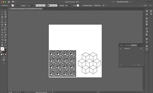
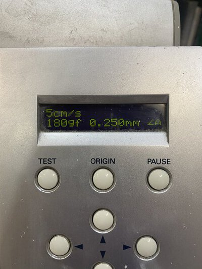
Testing and setting Parameters
After loading the material as a roll, I used these settings:
Speed: 5cm/s
Force: 180 gf
Depth: 0.250mm
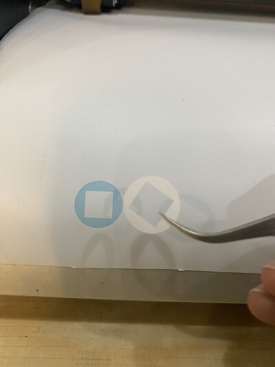
I tried the first test cut and it came out perfectly. The circle outside the inner square came out perfectly without cutting through the backing.
Loading file and cutting
So I loaded my design file and used the ai Roland plug-in to cut. The cutting was quite fast. Here is a picture of the vinyl still loaded: 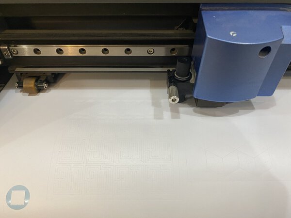
Peeling Vinyl
After finishing, I unloaded the vinyl and cut out the parts separately. 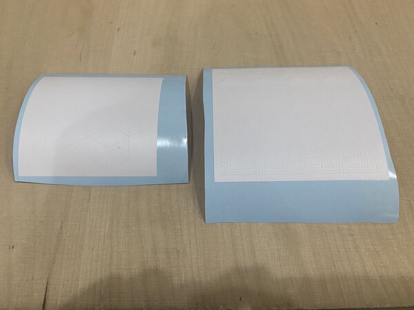
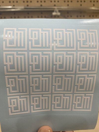
I then used a nose-end tweezer and started to remove all the negative parts. It actually took some time, as they were as thin and intertwined with the positives. Here are some pictures of that process: 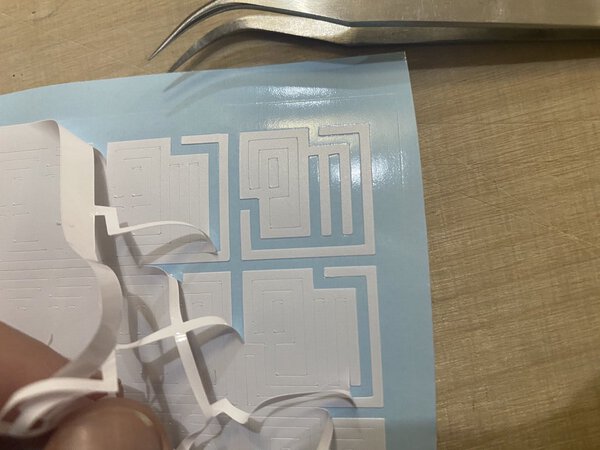
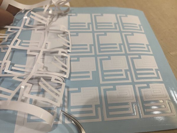
And this is how it looks like:
I haven’t yet applied to any surface, but I will have to do this step carefully, as the parts are quite thin.