Machine Design
Contents
- Idea
- Inputs and Outputs
- Electronics Design and Production
- CAD
- Lasercutting
- 3D printing
- Assembly
- Programming
- Hero Shots
- Design Files
- References and Important Links
1. Idea
This week was one of the weeks I tried to make a simpler project because:
1. Since I’m the only student enrolled this year I had to do it individually and not in a group.
2. The timeline to finish was very tight to do something more complex.
3. Had been in lockdowns or in different countries during the actual weeks / months of the course, so had no access to a lab.
4. Had about 1 week in late-October to finish, so couldn’t collaborate with people from different labs either.
However, initially I had some ideas like making a robotic arm, or making a CNC milling machine, but eventually I decided on making a fun game. Here is a CNC Hot Wire Foam Cutter with X,Y and a rotary embed I made during my time setting up FabLab Bombay in 2016.
I was thinking of a game that uses 2 movement axis, and instantly thought of this balancing marble game. For input I also wanted to use ultrasonic sensors in a way that movement could be mirrored by the motors like in this Ball and Beam project. But eventually decided to make an even simpler version and use a joystick module for control.
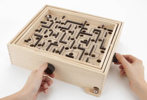
I had seen a manual version of this balancing game somewhere and thought it would be cool to make an electric version.
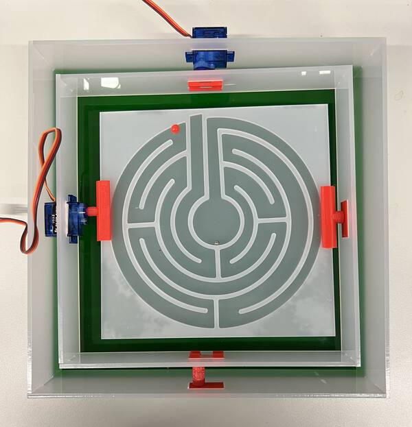
So by adding inputs and outputs I tried to make this game for machine design - an electronic version of a marble balancing game like this one.
2. Inputs and Outputs
It basically would need motors to rotate axes in two directions, and an input to help move the motors.
Outputs:
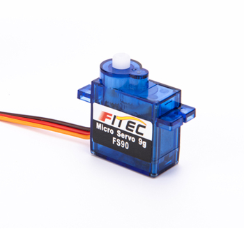
Two versions of servo are available - FS90 vs FS90R. FS90 offers closed-loop position control over a limited range. Alternatively, the FS90R is specifically designed to be a continuous-rotation micro servo that offers open-loop speed control. They have identical dimensions and use the same motor, but for my design I don’t need continuous rotation, so I select the FS90 motor - datasheet
Inputs:
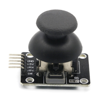
T move the plate on X and Y axis - I basically need a potentiometer for each direction. So I choose to use a joystick because it offers X,Y control in a single module.
Bill of Materials:
2x FS90 servo motors
1x HW504 joystick module
And for the microcontroller board:
1x LED 1206
1x 499ohm resistor
1x capacitor 1uF
1x ATtiny 44
3. Electronics Design and Production
The servo motor pinout suggests it needs a VCC, GND and one PWM pin.

The joystick module uses a VCC, GND, an ADC Pin for X axis potentiometer and one for Y axis. It also has a switch in Z, but I will not use it for now.

So I need 4 i/o pins - 2 PWM and 2 ADC.
Plus tx-rx, miso mosi to connect to ISP programmer. Needs 3 connections to VCC 5V and GND.
I added a capacitor between to vcc and gnd and an LED to indicate power.
So I chose a ATtiny microcontroller with enough pins and flash memory to play around with the code and configuration.


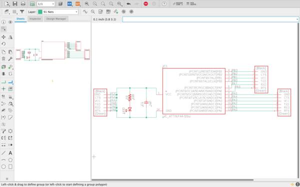
Next I make the pcb in Eagle. I follow the design process described in electronic design week to make it. Here are the schematic and and the pcbnew of the board.

Here are the traces and outline of the board:
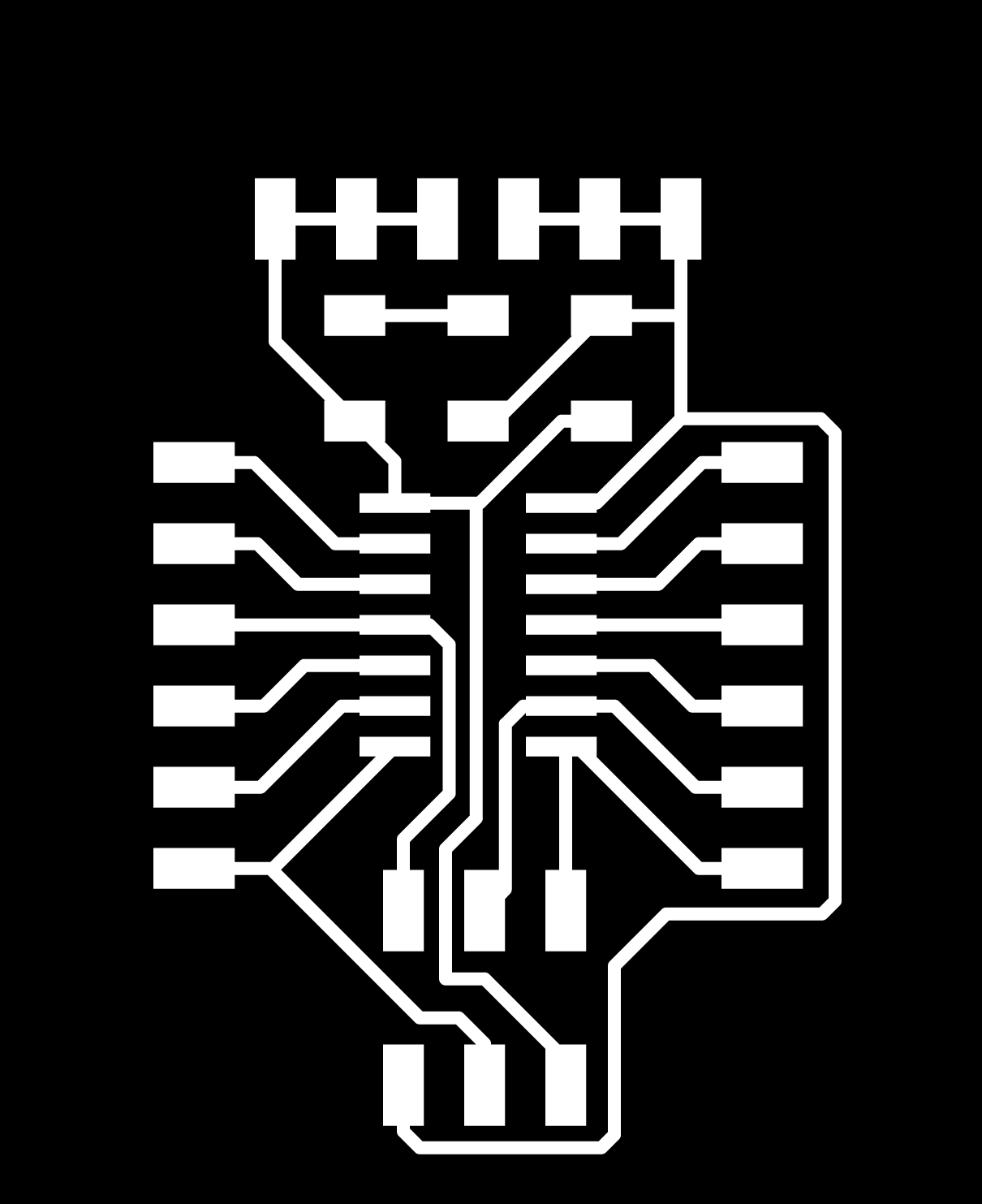

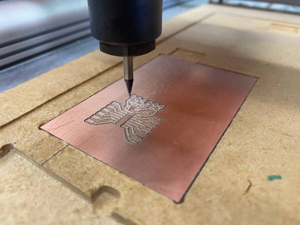
I followed the workflow described in Electronics Production week to fabricate the board, solder components.
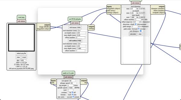
Cutting:
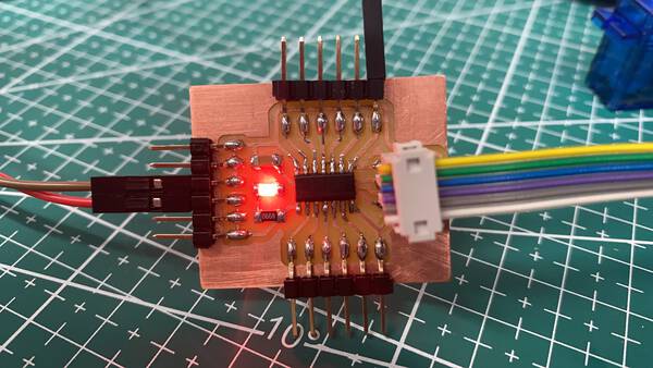
After soldering components, I plugged it in using a FabISP to test it. The power LED came on and I ran an avrdude to confirm that it is detected on my computer.
4. CAD
Next, I made a quick sketch to understand the movement required for the 2 axes.

And then started modelling it in 3D in Rhino.
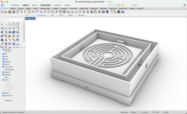
I make this model according to the 3mm acrylic available in the lab.
5. Lasercutting
The Universal laser in Fablab SP (makerspace) had a kerf of 0.1mm on testing. So I offset this and prep a cutting dxf that
I open in the laser computer to cut.
I checked if the servo motor fixes properly in it’s slot to check dimensions.
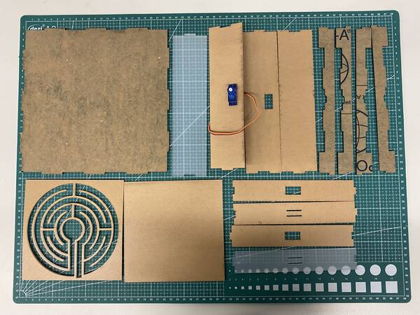
I follow the workflow described in Computer controlled cutting week, and the process is very smooth.
6. 3D printing
The joints between the acrylic and the motors, and the opposing pivot joints I decide to 3D print. This offers me quick and customisable option to afix these.
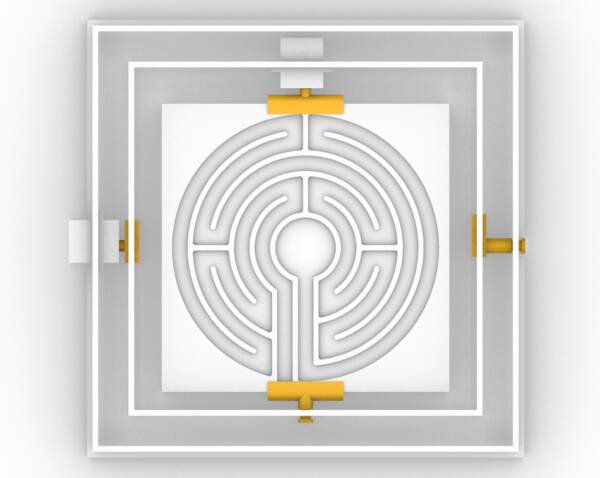
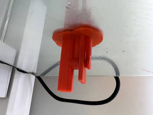
Here are the four different joints:
Inside pivot joint:
Inside servo joint:
Outside servo joint:
Outside pivot joint:
I used the tolerances of the 3D printer in FabLab SP for this. These settings are represented on the 3D printing and scanning documentation page. I followed the design rules and settings indicated there.
I have attached the 3D cad files and the gcode for these at the bottom of the page.
7. Assembly
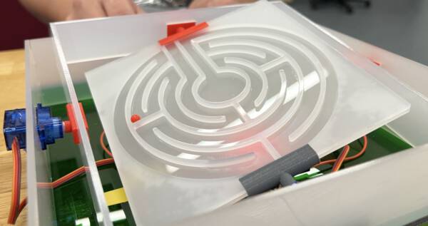
After getting all parts ready - acrylic body, 3D printed joints and the fabricated PCB it is time to assemble everything together. This is how it is now.
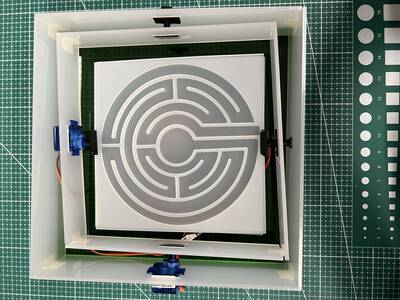
I realize that because of the horizontal position of the servo motors, the axis is not symmetrical. This will cause problems in the movement of the game. To solve this I redesign the 3D printed joints to be assymetrical as well, but in the opposite direction. This makes it even again.
8. Programming
Next I start to program the PCB. I do this in steps.
I first connect the servos to PA5 and PA6 pwm pins, and the Vx and Vy of joystick to A0 and A1 ADC pins respectively.
I connect all the VCCs and GNDs and connect the FabISP to program the target board.
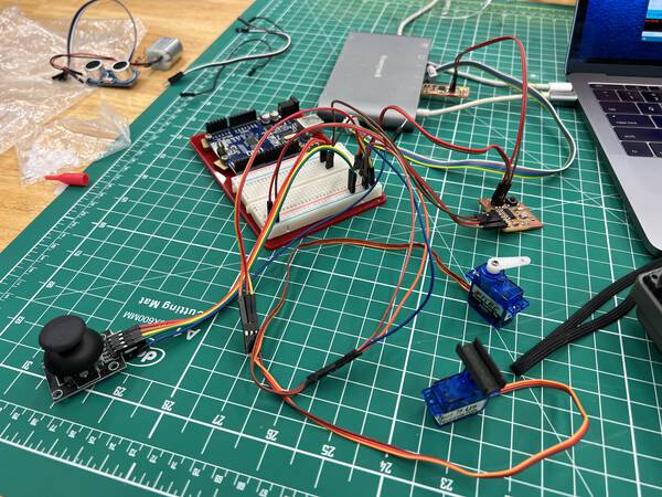
The first problem I face after uploading the sketch is that the servos make noise but do not move at all on operating the joystick. So I double check all connections with a multimeter, voltage with an oscilloscope and all the schematics.
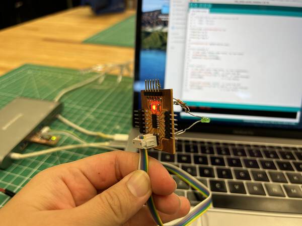
I replace the servos with a LED to check if the voltage is varying properly.
Then one by one I blink an led using all pins of the board to check the microcontroller itself. All seems to be fine.
I check the joystick module using serial write with an Arduino Uno. The joystick also seems to be working properly.
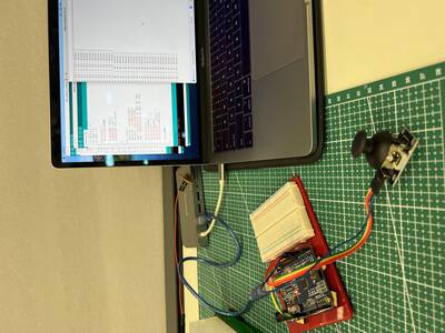
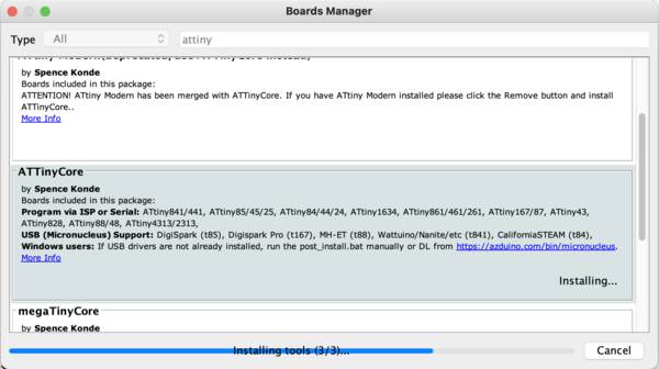
After a lot of head scratching, Steven had a eureka moment and asked me to check my board manager on Arduino Uno. I was using the Hi-Low Tech ATtiny platform core from David Mellis. Apparently this ATtiny core is quite old and doesn’t support servo & many other functions. So he suggests installing the Spence Konde platform core instead. This is the preferred, updated library. I try this with the servo Sweep sketch from examples and it works.
Finally I put everything back in place, and the servos are now on and can be operated using the joystick.
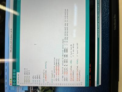
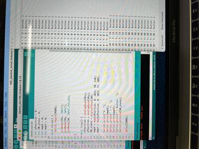
As shown in the video, the servos keep dancing and vibrating when the joystick is in neutral position. TO solve this I connected the joystick and read it’s voltage on the serial monitor. I used mapping to convert it into degrees. And found that in the X and Y axis didn’t have the same reading. I shifted the X till the servos became steady in neutral.
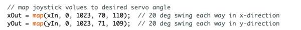
You can find the sketch here.
I reprogram the ATtiny with the new range. Finally it works properly.
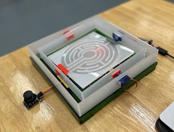
I put it all together. Fix all the wires and it is now ready to play.
9. Hero Shots
If I had to redo the assignment I would use motors that can be controlled with better precision and smoother movement.
I would use the motors vertically instead to make it symmetrical. I would also make a fixed space for the joystick instead of keeping it hanging on the wires.
10. Design Files
Joystick with serial monitor
PCB traces nc code
PCB outline nc code
All 3D printed joints - stl + gcode
Machine code
Machine (Rhino) 3D model
Machine Lasercut file - dxf
Program Code
PCB Eagle files + nc files for stepcraft