12. Output devices
In this week, I tested two output devices that I might use for the final project, a servo motor and an RGB LED. In the group task, we measured the power consumption of an RGB LED.
Assignment
Individual assignment
Add an output device to a microcontroller board you’ve designed, and program it to do something.
Group assignment
Measure the power consumption of an output device.
Group Assignment
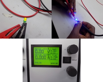
For this task, we (Alok, Jobin, Sahan, and Yasir) measured the power consumption of a 5 mm LED and an RGB LED (the one used in the individual assignment above). The consumption of the LEDs was measured by directly powering them with a variable power supply and varying the voltage and current in order to measure the resulting effect on the brightness of the LEDs.
In both tests, we burnt out the LEDs by exceeding their voltage and current limits. For the 5 mm LED this was 6.5 V and 188 mA (it is probably lower than these values). Blue and Green LEDs can be fed with a maximum current of 100 mA (Peak Forward Current) for a very short time without being damaged 2. The peak forward current is the absolute maximum current that an LED can handle and this is only for a short period of time. The peak forward current, specified on a datasheet, can only be applied to an LED for the time period specified. This time period is either specified as a fraction of a duty cycle or as a time in milliseconds 3.
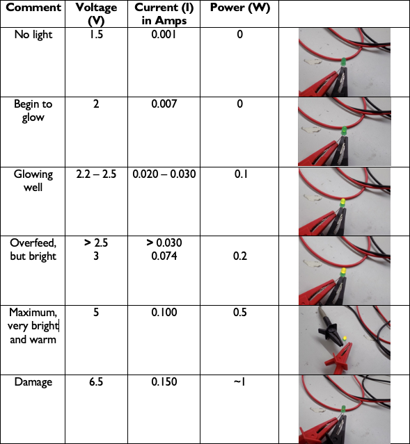 Measurement values for 5 mm Green LED
For the RGB, we repeated the same process as with the 5 mm LED, testing the effect of varying the voltage and current on the brightness. If current is increased the LEDs brighten and if decreased, the LEDs become dimmer. According to the data sheet, this LED has Forward Voltage ranging from 2 - 4 V. 2 - 2.6 V for Red, 3.2 - 4 V for Green, and 3.2 - 4 V for Blue. The absolute maximum ratings for the Forward Current (the current flowing across the LED from positive to negative in order for the LED to get power) for Red is 50 mA and for Green and Blue it is 25 mA (milliamps) when powered individually as we did. We tested the power consumption from a low of 1.60 V and 0.001 Amps, which didn’t power on the LED, to a high of 6.5 V and .200 A. Red was very dim at 1.9V and 0.001 Amps and the optimal value was 2.3 V and 20 mA. With the recommended electrical characteristics of 20 mA, Red has an average forward voltage of 2.0 V, Green 3.2 V, and Blue 3.2 V, respectively.
Individual assignment
For this assignment, I used the board from the previous week to test the FS90R continuous servo.
The FS90R is a micro-sized servo specifically for continuous rotation. At 6 V, it has a maximum rotation speed of around 130 RPM (no-load) and can produce up to 21 oz-in (1.5 kg-cm) of torque. The servo can be controlled using a direct connection to a single microcontroller I/O line without any additional electronics 1.
To test the servo, I used this sample code. Below is a video of the servo. Not yet sure whether I will use the same one for the final project, though.
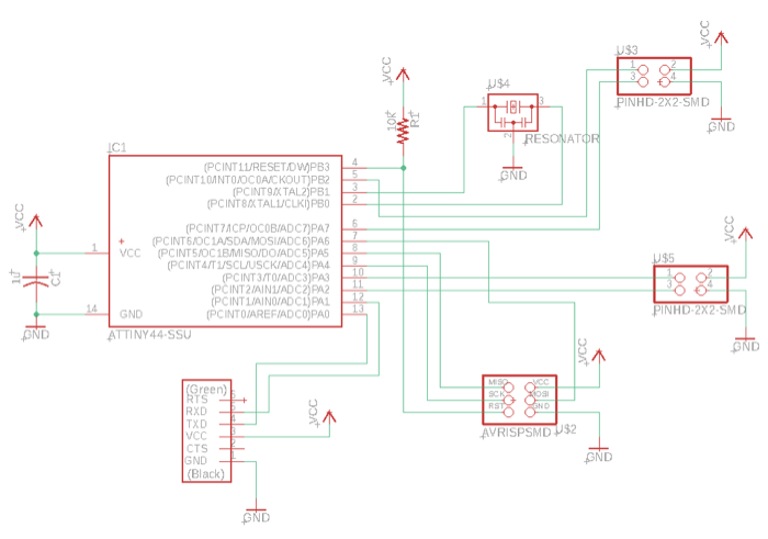
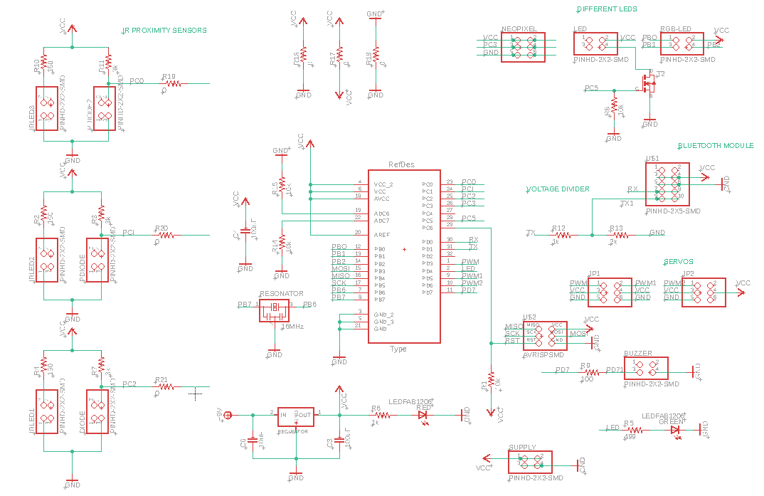
I also made a new schematic with just an RGB LED.
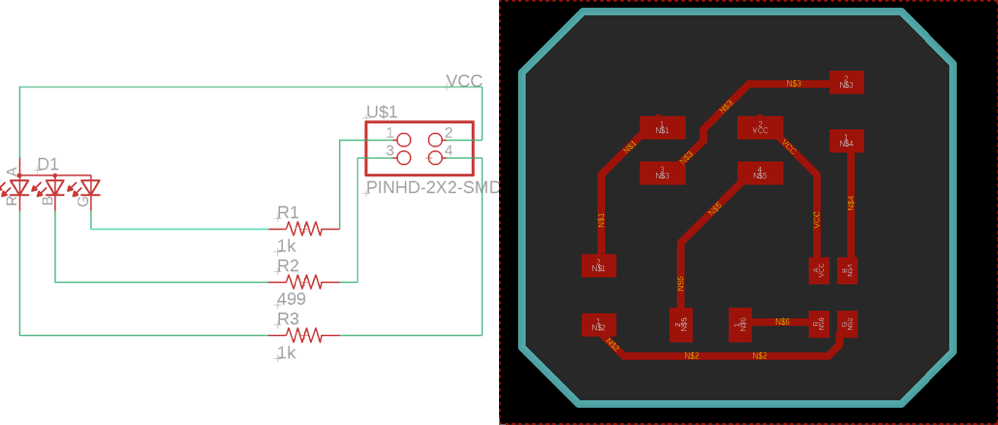
By reviewing the data sheet, I was able to solder the board in the right orientation after the Eagle design and rml files were ready.
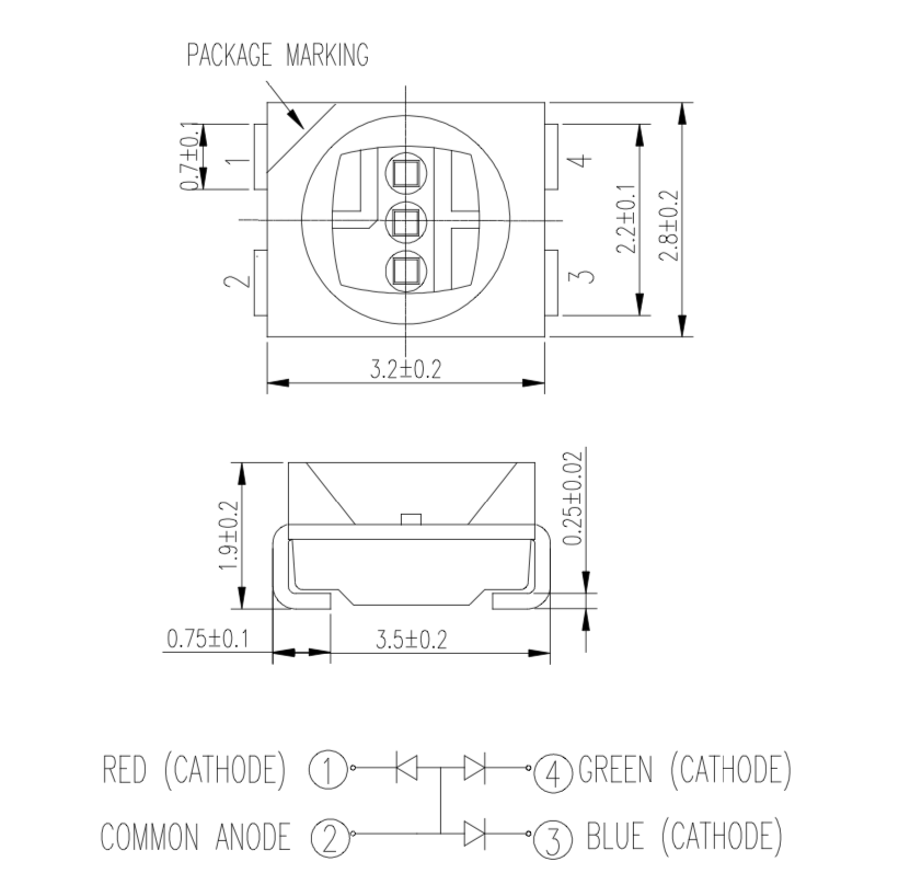
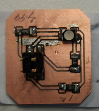
Image of the soldered board.
When I first tried the LED, it was only showing one colour and I couldn’t find the problem as I had earlier checked for continuity and the board seemed to be fine (or so I thought). When removing the jumper cables from the board, the header pin came off so the soldering was not good. After re-soldering the header, the LED worked, although green was not as bright as red and blue. Video of the blinking LED below.
In this week, I also started working on the board to be used for the final project which included (or at least this was the initial plan) pin headers for all the components that I intend to use. The schematic design took a bit of time but finally got it approved.
The board design is another matter completely! After multiple tries, I still can’t get the routing to 100% even with the use of multiple jumpers. The highest it has reached so far is 76%.
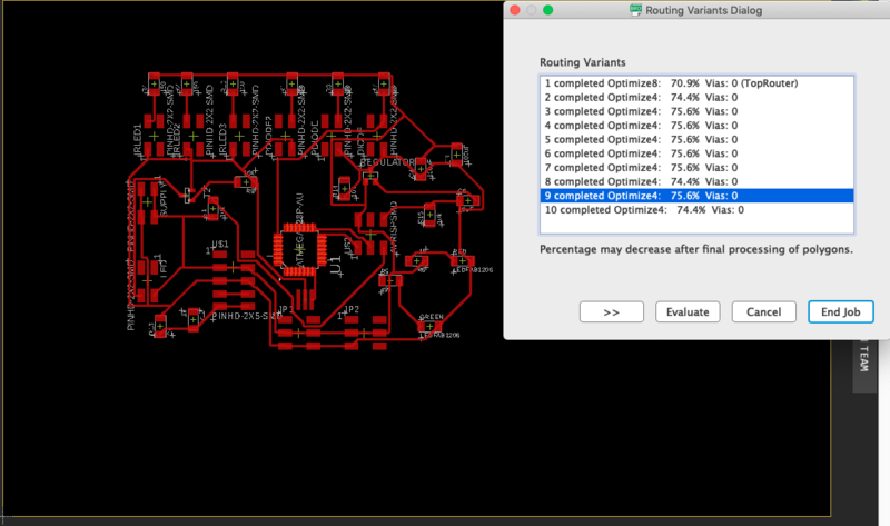
Now I am thinking of splitting the overall design and having at least the IR proximity sensors on a separate board and use headers to connect the IR sensor board to the main board. With this component removed, maybe it will be easier to route the main board. Although, Antti suggested to try to get everything working on the main board, but this has already taken longer than I would have liked it to. As there are more demanding assignments coming up, if separating the components in different boards works even though it might lead to a bit extra work , then that is the option I will go for if it fastens the process of creating the design files. Or, I will just use fewer components and build on the project later.