10. Molding and casting
This week we reviewed data sheets for the molding and casting materials and we compared test casts with three different materials in our group. For the individual work, I designed a Sphere, milled it and used it to cast pasts.
Assigment
Group task
- Review the safety data sheets for each of your molding and casting materials, then make and compare test casts with each of them
Individual task
- Design a 3D mold around the stock and tooling that you’ll be using, mill it, and use it to cast parts.
Group assignment
Prior to the group work, our instructor Ari gave us a rundown of molding and casting. Ari presented the process of creating molds, the available materials and the safety requirements when molding and casting as contact with any of the materials may cause irritation to the skin and eyes. It is important to work in a well-ventilated room, to use safety gloves (vinyl gloves only), glasses and a lab coat. He also emphasised the importance of going through the safety data sheets and the safety instructions for the different materials prior to molding and/or casting.
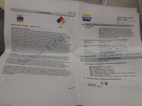
I did the group assignment with Alok and Arash. We went through the data sheets for each of the molding and casting materials we tested.
For the group assignment we tested:
-
- No Vacuuming – No Scale – Easy To Use . . . OOMOOTM 30 is an easy to use tin cure silicone rubber compound that features convenient one-to-one by volume mix ratios (no scale necessary). Both have low viscosities for easy mixing and pouring . . . vacuum degassing is not necessary. Both products cure at room temperature with negligible shrinkage. OOMOOTM 30 has a 30-minute pot life, with a six-hour cure time.
-
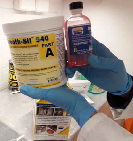
- Smooth-On Smooth-SilTM Platinum Silicones cure at room temperature with negligible shrinkage. With different hardnesses to choose from, Smooth-SilTM products offer tremendous versatility and are suitable for making production molds of any configuration, large or small. These silicones exhibit good chemical, abrasion and heat resistance. Materials such as plasters, concrete, wax, low-melt metal alloys or resins (urethane, epoxy or polyester) can then be cast into these silicone rubbers without a release agent… Smooth-SilTM 940, 950 and 960 are suitable for food related applications.
-
- The Smooth-CastTM 300 Series of liquid plastics are ultra-low viscosity casting resins that yield castings that are bright white and virtually bubble free. Vacuum degassing is not necessary. They offer the convenience of a 1A:1B by volume or 100A:90B by weight mix ratio. The differences between them are pot life and demold time.
Overview of the materials
| Material | Mix ration by volume | Mix ration by weight | Pot life | Cure time |
|---|---|---|---|---|
| OOMOOTM 30 | 1A:1B | 100A:130B | 30 minutes | 6 hours |
| Smooth-SilTM 940 | 100A:10B | 100A:10B | 30 minutes | 24 hours |
| Smooth-castTM 300 Series | 1A:1B | 100A:90B | 7 minutes | 30 minutes |
Molding and casting
For molding, Ari gave us the molds made in the previous year’s assignment to cast.
We started with OOMO and throughly mixed the two parts ensuring that they were no colour traces left from either of the parts and placed it evenly on the mold. If measuring by weight the proportions should be 100A:130:B
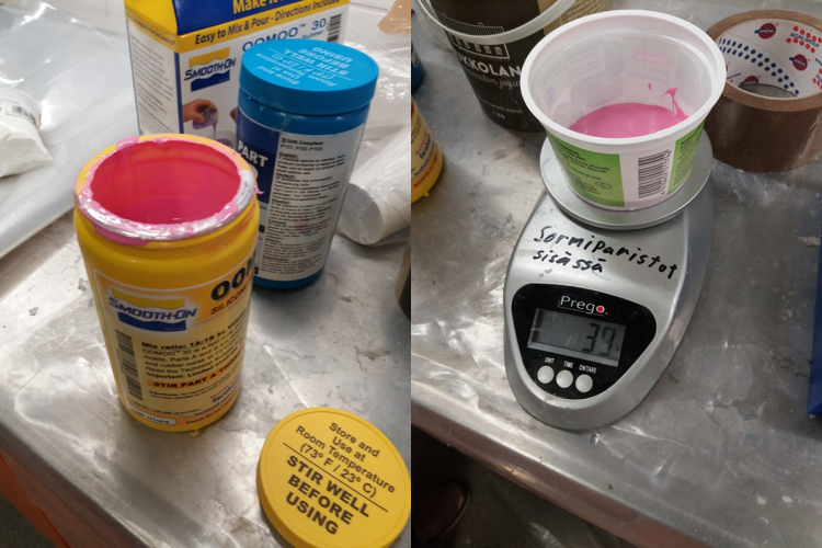
Next we used Smooth-Sil 940 that has the mix ratio of 100A:10B.
We weighed the parts on a scale, mixed them throughly, degassed the mixture and poured it into the mold.
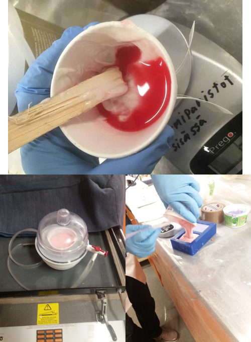
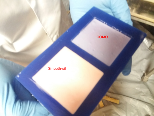
Below are the final results after curing.
Individual assignment
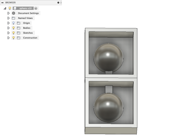
3D mold design
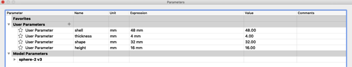
I first defined the parameters for the design. For the sphere, I just named it shape in case I opted for a different design/form.
I then created a sphere: CREATE > Sphere.

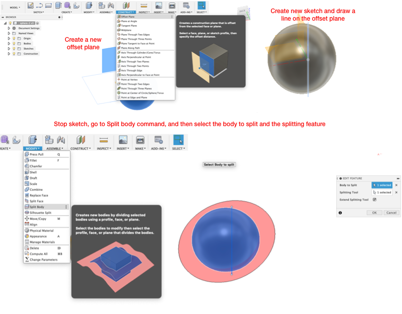
I wanted to split the sphere in half so I created a new offset plane (CONSTRUCT>Offset Plane). On a new sketch, I drew a construction line cutting along the diameter of the sphere and stopped sketched. Then, I chose the split body option (MODIFY>Split Body) and in the dialog box selected the sphere as the Body to Split and the construction line as the Splitting Tool.
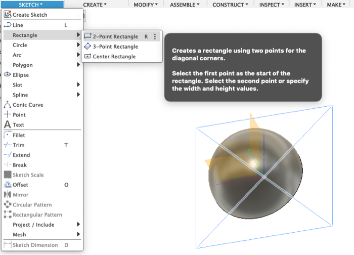
On a new sketch, I drew a rectangle with the shell dimensions specified in the parameters.
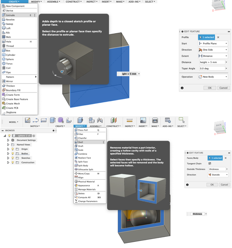
I extruded (CREATE>Extrude) it to fully enclose the split sphere (the radius of the sphere plus 5 mm) and created a shell (MODIFY>Shell) from the extruded rectangle with a thickness of 4 mm.
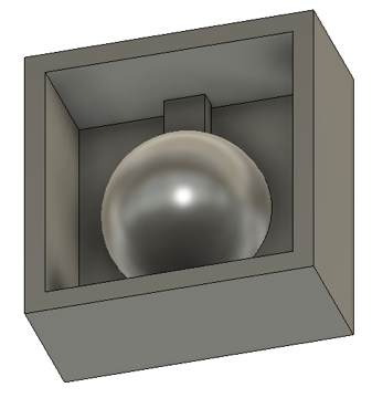
Finally, on a new sketch on the outside of the shell, I drew a small rectangle for the casting entrance and extruded it. For the extrusion extent, I chose To Object, and selected the semi-sphere as the Object. I saved the design as an STL file to be exported for the milling process.
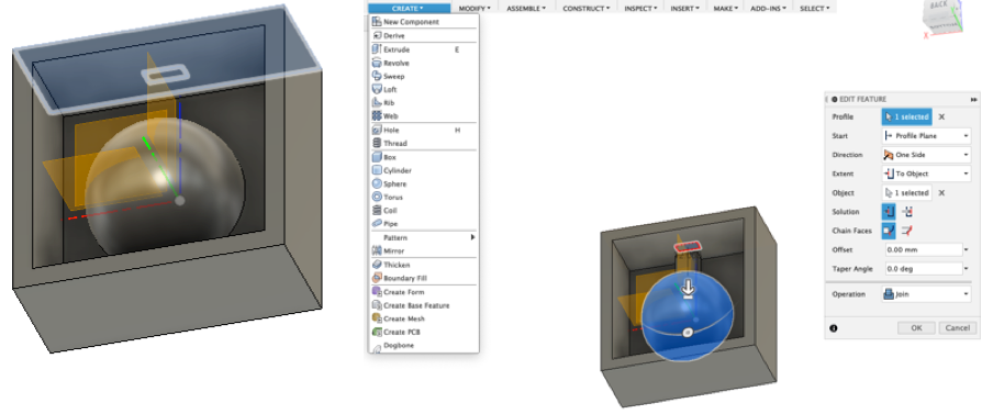
An image of the final result below.
Milling the mold design
For the milling process, we (Ari helped to set the tool paths) used MODELA Player 4 to set the file configurations for milling and used VPlayer to position the wax mold along the X,Y, and Z axes in Roland SRM-20 CNC-milling machine.
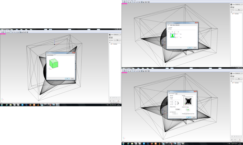
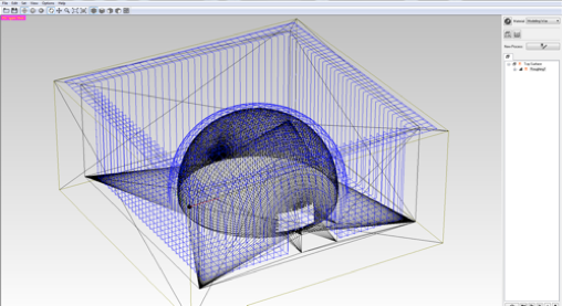
After importing the STL file into MODELA, you check that the size and orientations are correct by setting the origin (Set > Model > Origin) to match the setting of the milling machine. Then you set the margins (Set> Modeling Form > Margin). Ensure that values for margin are zero and leave the other values as they are. Other settings don’t need to be changed, because the mold is designed with both margins and slope. From depth, you check the maximum depth (height) of the milling process, this is a useful value for selecting and positioning the tool.
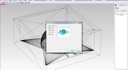
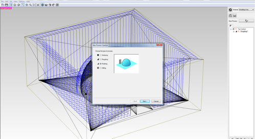
After the origin and margin are set, you create a new process where you select the tool and set the cutting parameters for the milling process. Set > New Process >
The first process is Roughing.
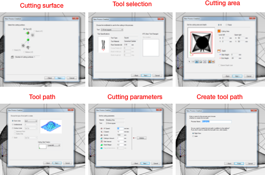
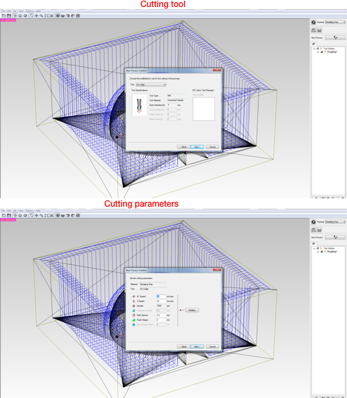
Clicking next opens the selection of the cutting surface (Top [+Z]). Then you choose the tool for cutting in the roughing process. I selected the Flat 3.18 mm which was already defined in the system. The cutting area and depth for my design was correct. The next option was choosing the tool path to create. I chose Scan Lines (X + Y) and Cutting Start Position as lower left. In cutting parameters, the XY Speed was set at 30 mm/s (horizontal speed of the milling tool), Cutting-in Amount to 1 mm (Depth of the cut) and Path Interval to 1.5 mm (offset between parallel cuts). Finally, you create the tool path for the roughing process.
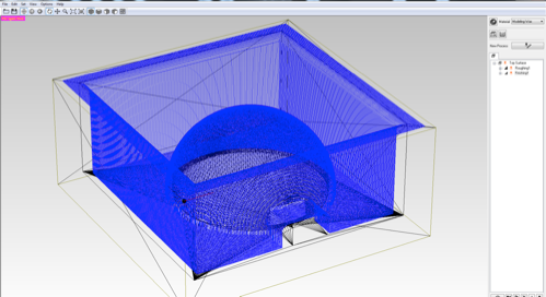
Calculated tool path for roughing process
After tool paths for roughing are calculated, you create a new process again Set > New Process > and select Finishing which creates a smooth surface.
The settings for finishing were similar to roughing, apart from the cutting tool and the cutting parameters which are shown below. I changed the cutting tool to R1.5 Ball which had its own cutting parameters for the finishing process.
 .
.
Calculated tool path for finishing process
In cutting parameters, the XY and Z Speed were set at 24 mm/s (horizontal and vertical speed of the milling tool), Path Interval to 0.2 mm (offset between parallel cuts), and the Finish Margin to 0 mm. Finally, you create the tool path for the roughing process.
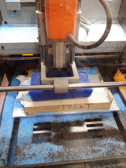
When the file was ready, the milling bit should be changed to flat 3.18 mm tool for roughing, the wax mold placed on the base of the milling machine and as explained in Electronics Production, use VPanel for SRM-20 to position the axes. Then in MODELA Player, press the cut button in the bottom right corner (or File > Cut) which opens the Output dialogue box where you press Continue.
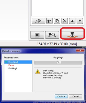
The milling tool has to be changed in between the Roughing and Finishing. Below are images of milling and another one after the completion of both processes.
Casting the mold
I used OOMOOTM 30 to make the molds for the sphere.
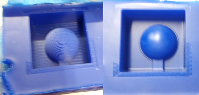
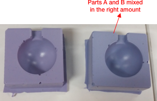
When mixing the materials for the first mold, I made a mistake with the proportions and was told that the result might not turn out well. Luckily, it was not too bad after curing. The difference between the colouring of the two molds can be seen below. I also did not do a very good job of clearing the air bubbles when casting the mold.
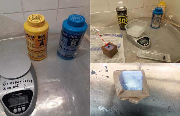
Casting the two-part mold with Smooth-cast
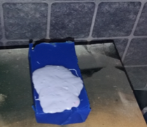
I used Smooth-cast 305 to cast. Smooth-cast 305 has a pot life of 7 minutes and cures in approximately 30 minutes. Using tape, I attached the two-part mold, measured the parts on a scale, mixed them (100A:90:B) and used a Syringe to fill the mold through the casting hole. The process is outlined in the image below.
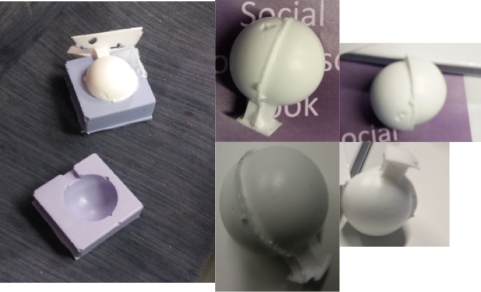
The cast could have been better, but it was satisfactory.
Original files
Reflection
This was another week where I learned something new. As in the CNC machining week, I never really think about how different-shaped products or molds are created and it was interesting (but patience-testing) to go through such a process. I got to learn about different materials for molding and casting by testing some of them and reviewing their data sheets. It was interesting to learn about 3D design for creating molds and generating tool paths for milling the designs.
For the 3D mold design, I considered different designs but as I was having problems (as usual) figuring out the object to make, I settled on a sphere which did not take too much time. Even though the sphere was a simple design, it took a surprisingly long time to mill. Added to the time it takes to cast, this is one of the weeks that needed careful planning.
In order not to risk wasting the six hours it takes for Oomo to cure because of incorrect proportions, I thought I would mill another mold design and cast it before the six hours were up. This second milling process took even longer than the first one and after it was done, we checked the earlier mold and it wasn’t ruined as feared, but it needed a bit of extra curing in the oven.
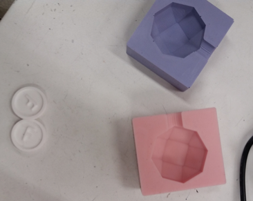
The time spent on milling could have been spent doing what I am now doing (documenting). Another mistake I made was not milling a two-part mold as I had to cast the mold twice after a six-hour interval and the two parts were not symmetric (Michael)!
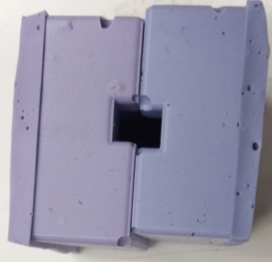
To fix the alignment problem, I should have just milled a two-part mold (image below). I had the 3D design for both (for the two-part, I just mirrored and aligned the second part) but thought it would “save time” if I milled just the one part. As I wanted to do a two-part mold for casting, it ended up taking triple the time it would have taken. I also missed the registration and a tube to allow the flow of air while pouring the casting material. For the registration, Í should have followed Neil’s suggestion and instead of using tabs, the mold should be designed in such a way that one mold can be inserted into another.