6. 3D Scanning and printing
In this week, I learnt about the design rules for 3D printing by testing a few 3D printers. I also scanned, designed and printed 3D objects.
Tasks
Group task
- Test the design rules for 3D printers
Individual task
- Design and 3D print an object (small, few cm3, limited by printer time) that could not be made subtractively.
- 3D scan an object (and optionally print it).
The goal for this week is to identify the characteristics of 3D modelling processes. The advantages and limitations of different 3D printing software and processes and to learn about 3D modelling, scanning and printing.
Group task
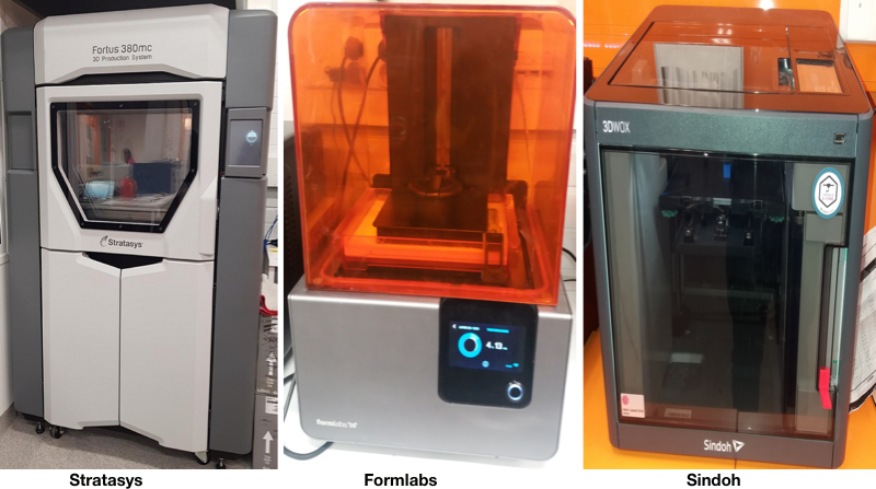
For the group task, I worked with Arash and Alok to test 3 printers: 1) Stratasys Fortus 380mc that uses ABS (Acrylonitrile butadiene styrene), 2) FormLabs that uses stereolithography (SLA) to form the models from resin, and 3) Sindoh 3D Vox that uses PLA (Polylactic acid).
We used the same test piece as the other groups and in order to save time, we sent multiple print jobs to the printers (Stratasys and FormLabs): the test piece and our own designs. When sending the designs for printing, it is possible to specify different settings for each design. We used Test your 3D printer file for testing.
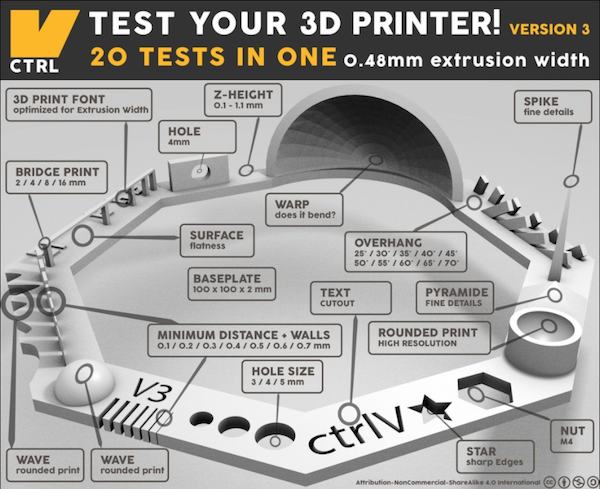 Test your 3D Printer
Stratasys Fortus 380mc
Stratasys is based in Fused Deposition Modelling (FDM) technology. An additive manufacturing process that prints from bottom to top layer-by layer.
Formlabs
Formlabs is based on Stereolithography (also known as optical fabrication, photo-solidification, or resin printing) technology. An additive manufacturing process where a laser beam builds up a model layer by layer from liquid polymer that hardens on contact with the laser light. After printing, the model(s) is first cleaned in Isopropyl alcohol, and then cured in 405 nm light. As it uses Class 1 laser and toxic resin, precautions should be taken to use it safely. The safety guidelines can be found here.
Sindoh
This printer uses Fused filament fabrication (FFF) technology, a 3D printing process that uses a continuous filament of a thermoplastic material. It does not use different material for the model, support or bedding. This printer does not add supports and a hollowed design like the one described below in the individual task would not have turn out well in this printer.
The process for testing each of the printers is described in Alok’s page.
| Syntax | Fortus 380mc 3D | Formlabs | Sindoh 3D Vox |
|---|---|---|---|
| Nut, Size M4 Nut fit | Pass | Pass | Pass |
| Wave, Rounded Print | Pass | Pass | Pass |
| Star, Sharp Edges | Pass | Pass | Pass |
| Text Cutout, Complex Shapes | Legible | Best | Good |
| Holes, Size 3, 4, 5 mm | Pass | Pass | Pass |
| Minimal Distance: 0.1, 0.2, 0.3, 0.4, 0.5, 0.6, 0.7 mm | 0.5 | 0.2 | 0.4 |
| Z height: 0.1, 0.2, 0.3, 0.4, 0.5, 0.6, 0.7, 0.8, 0.9, 1.0, 1.1 mm | Pass | Pass | Pass |
| Bridge Print: 2, 4, 8, 16 mm | Pass | Not clear | Pass |
| Sphere, Rounded Print 4.8mm height | Pass | Pass | Pass |
| Sphere Mix, 7 mm height | Pass | Pass | Pass |
| Pyramid, 7 mm height | Pass | Pass | Pass |
| Overhang: 25, 30, 35, 40, 45, 50, 55, 60, 65, 70° | Pass | Pass | Pass |
| Warp, does it bend? | No | No | No |
| Printed object | 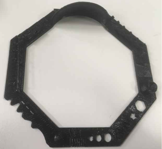 |
 |
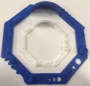 |
Individual task
3D design
I did my 3D design in Fusion 360. For this design task, the aim was to design additively, meaning an object that could not be milled or laser cut. For this, I chose to design a cube inside another cube. Additive manufacturing is designing by layering components whereas subtractive is when layers are cut from a design until the desired model. The design outlined below is only possible to fabricate using additive manufacturing because the inner cube’s dimensions are slightly bigger than the holes on the sides of the bigger cube, the two cubes are not attached, the smaller cube moves freely inside the bigger one and it can’t come out through the holes.
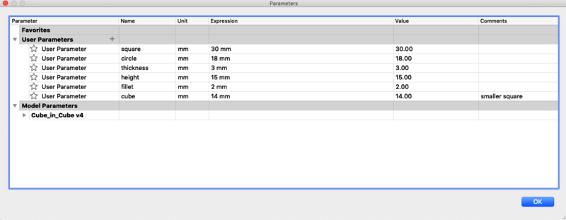
Before beginning, I first defined the parameters as shown below.
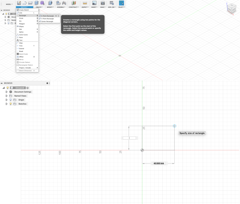
After, I clicked on SKETCH>Rectangle>2-Point Rectangle. Click on the XY plane to go into top view, from the origin I drew the square with the parameters I defined in the above image. When the measurements are correct, I pressed enter on the keyboard twice to exit the sketch.
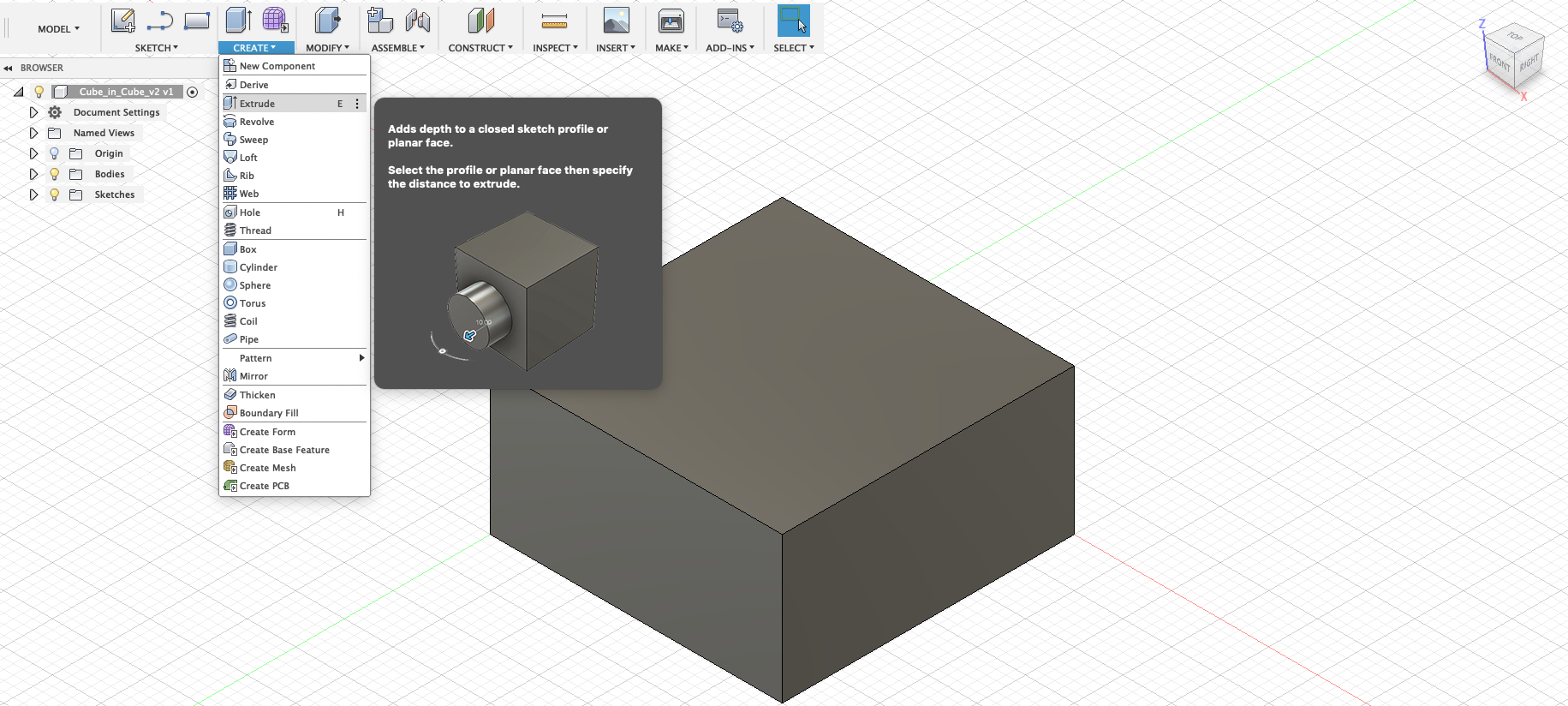
Then, CREATE>Extrude click on the rectangle and pulled it up with a height of 15 mm.
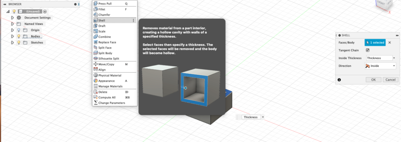
I selected MODIFY>Shell clicked on the top surface of the rectangle and shelled it out to 3 mm wall thickness (defined in the parameters).
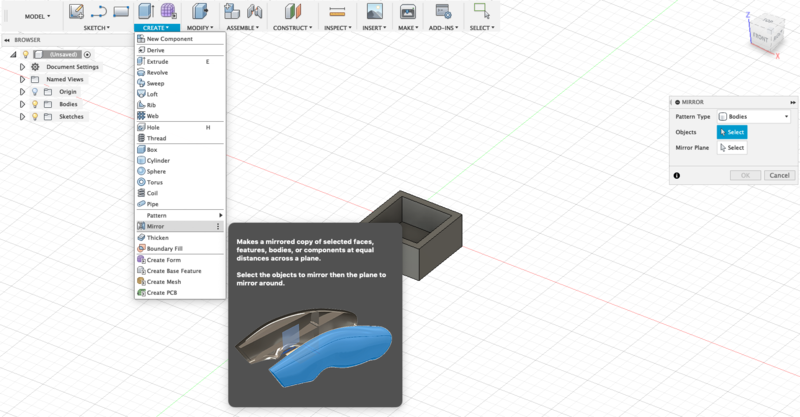
I mirrored the box (CREATE>Mirror). In the Mirror dialogue box, ensure Bodies is selected and click on the rectangular object to select it. Then in Mirror Plane, click on the top face of the object and click OK.
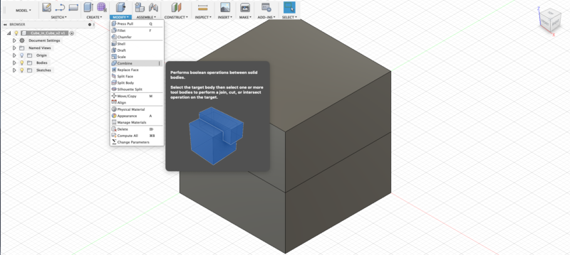
Then I combined the mirrored objects to form a cube (MODIFY>Combine). In the Combine dialogue box select both objects, ensure Operation is on Join and click OK.
Next, I cut 18 mm diameter holes (also defined in the parameters) through the sides of the cube (SKETCH> Centre Diameter Circle and selected one side of the cube). From the centre point of one side of the cube, I drew the circle and exited the sketch. Went to CREATE>Extrude, clicked on the circle sketch (first picture in image below) and then cut a hole through the cube (second picture in image below).
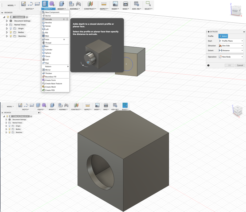
I repeated the process on the other two sides and ended up with the image below.
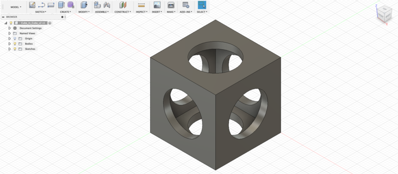
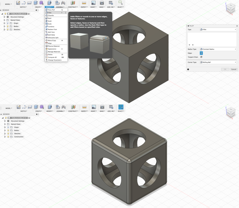
Next, I clicked on each of the 12 corners of the cube and rounded the edges by 2 mm (also defined in the parameters) (MODIFY>Fillet)
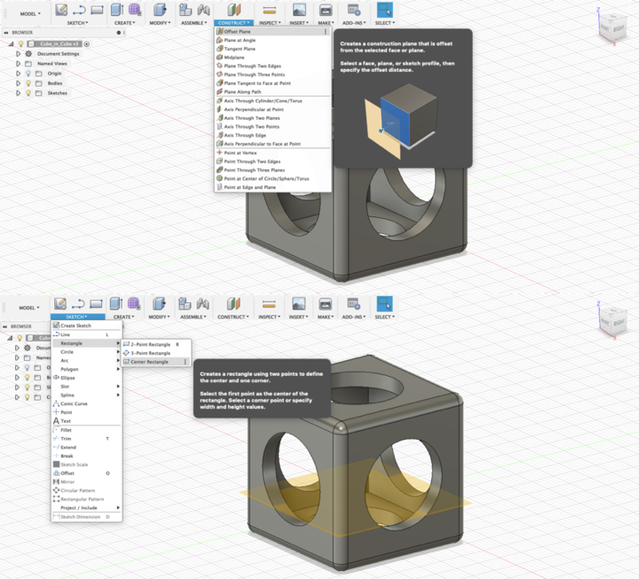
I inserted a 14 mm square cube in the centre of the hollowed cube on an offset plane. To do this, I selected CONSTRUCT>Offset Plane, clicked on the top surface of the hollowed cube and moved the plane to the position where the bottom of the smaller cube should sit.
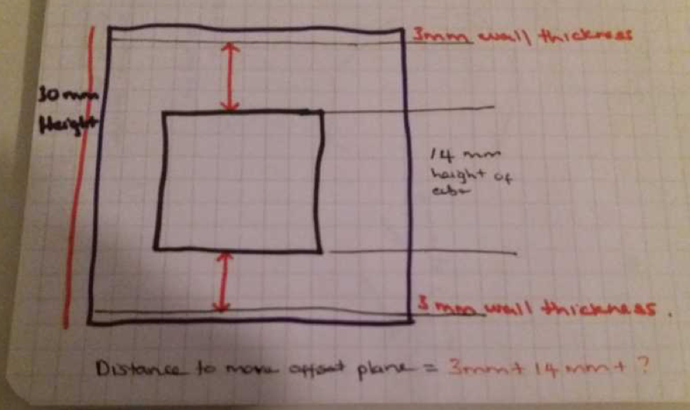
Below is a diagram showing the calculation for how far to move the offset plane where the bottom of the smaller cube will lay. The bigger cube was 30 by 30 mm and it had a wall thickness of 3 mm. In order to place the smaller cube inside the centre of the bigger cube considering it was 14 by 14 mm, the gaps needed to be 5 mm. Height of the cube (30 mm) minus the thickness (3 + 3 mm) minus the height of the smaller cube (14 mm). This leaves 10 mm.
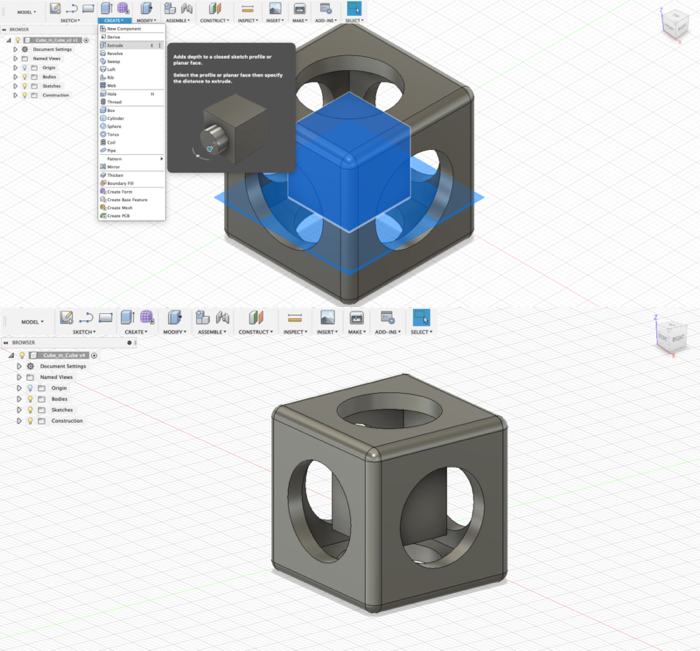
Then, I drew the 14 mm cube onto the offset plane (SKETCH>Rectangle>Centre Rectangle) by clicking on the plane, selected the centre point, and set the dimensions for the smaller cube. Next I extruded (CREATE>Extrude) the smaller cube by the same measurements defined in the parameters and ended up with the 2nd picture in the image below.
3D Printing
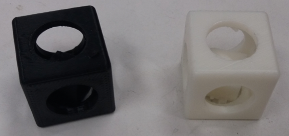
I printed the design in two different printers, the Stratasys Fortus 380mc and FormLabs. The designs were printed together with the test piece for the group work. The result was better in Stratasys Fortus 380mc than in Formlabs. After printing in both printers, the design needs to be dipped in a solvent solution to dissolve the support material. How long it takes to dissolve depends on how deep the support material is in the design. For example, if there are joints or tight corners, it will take longer for the material to dissolve.
First, I opened the STL file in the Insight program and the important settings from the main window are Part interior style (sparse), Visible surface style (enhanced), Support style (smart).
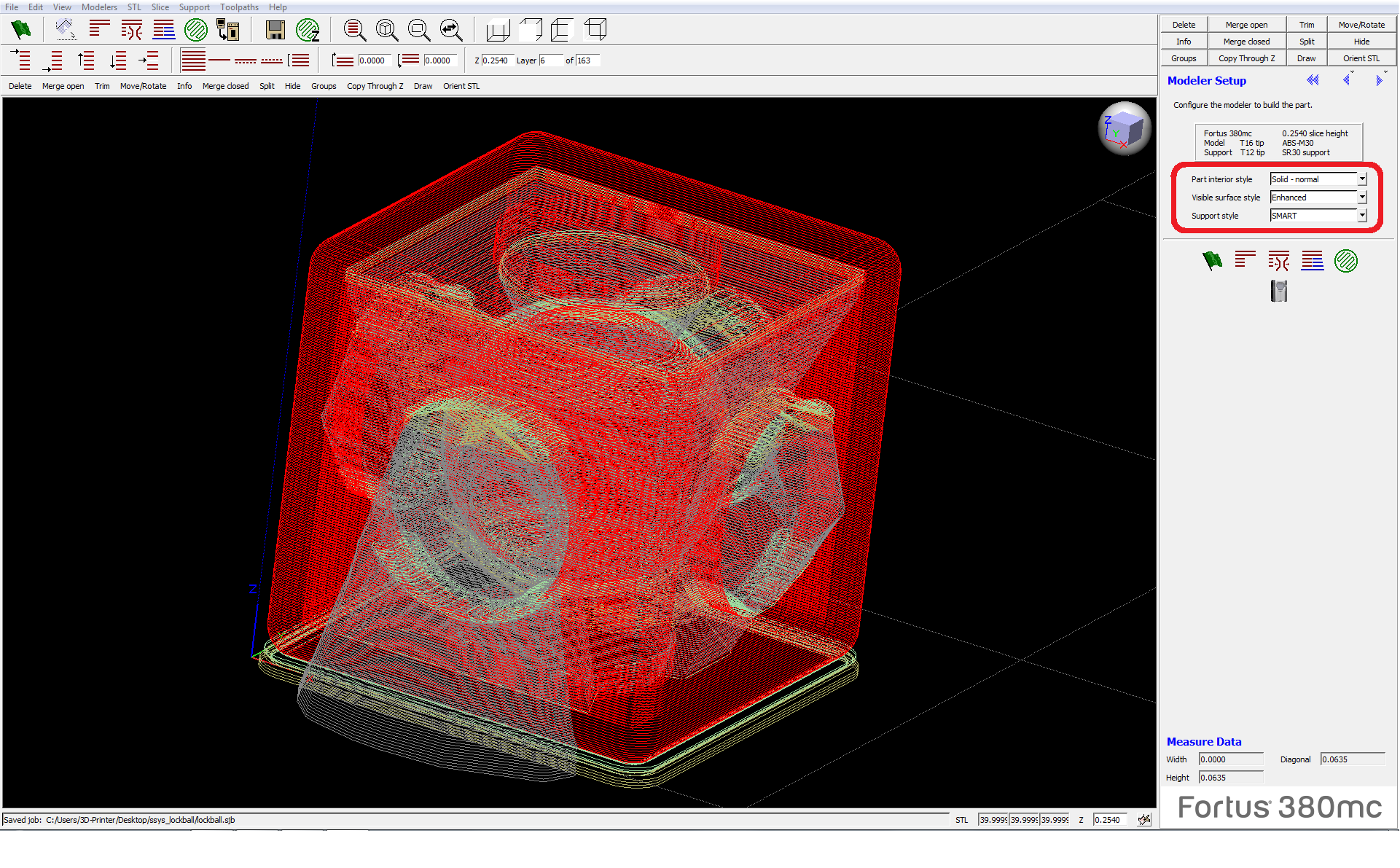
Then I pressed Finish and Built the job
Before printing, base material is inserted on the surface of the printer. After this, I selected the print job from the printing queue which is visible in Stratasys’ control panel. On the panel, you can see the actual printing time before proceeding and check if there is enough material available to successfully complete the printing. When everything is ready, press play.
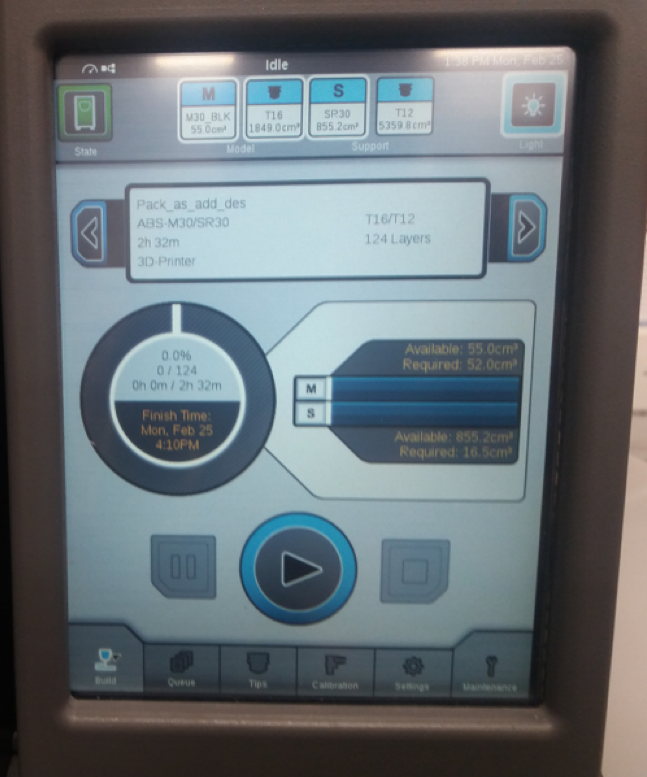 Stratasys control panel
When printing is done, there is a layer of ABS at the bottom and then a layer of support. This is because ABS sticks to the plastic sheet placed on the surface of the printer. The layer of ABS can be removed by simply pulling it out. The ABS on the bottom of the design should be removed because it blocks the solvent from going into the design (in my case, this was not a problem as my design was hollowed).
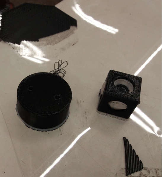 Printed design
Then I left my piece in lye overnight to remove the support material. For Formlabs, after printing the design is first cleaned in an alcoholic solution and then cured. This does not take as long as designs printed in Stratasys. Below are the final results.
3D scanning
For the 3D scanning, I tried two programs. One was Scann3D, a mobile application to enable true 3D model capture and reconstruction for smartphones and tablets, and the other was AutoDesk Recap Photo, a desktop and cloud solution with expanded photogrammetry capabilities.
Scann3D
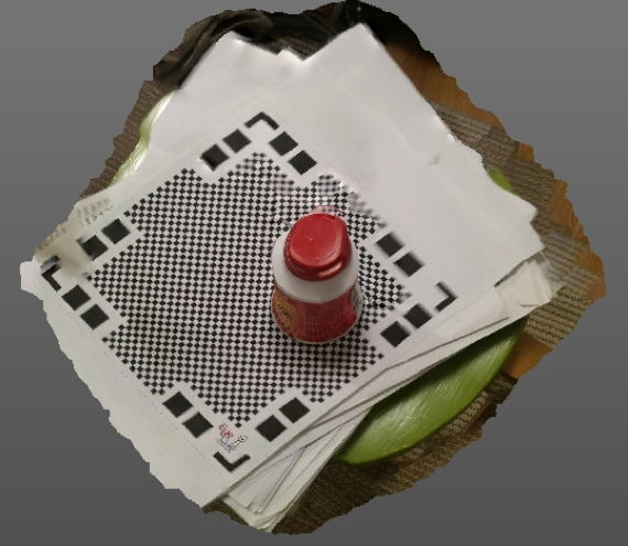
I first placed a vitamin tablet jar on a stool with a white and black printed paper. Then I opened Scann3D and used it to take about 2O pictures while going round the jar from different angles.
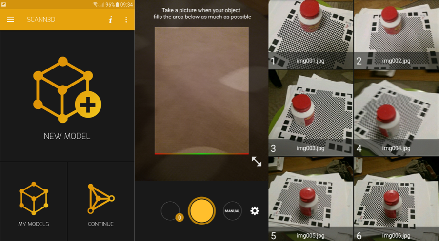
When the image set was ready, I simply tapped on a button in the application to create the model. Even though the specs for my phone are not excellent and I did not take good photos, the final model didn’t turn out so bad.
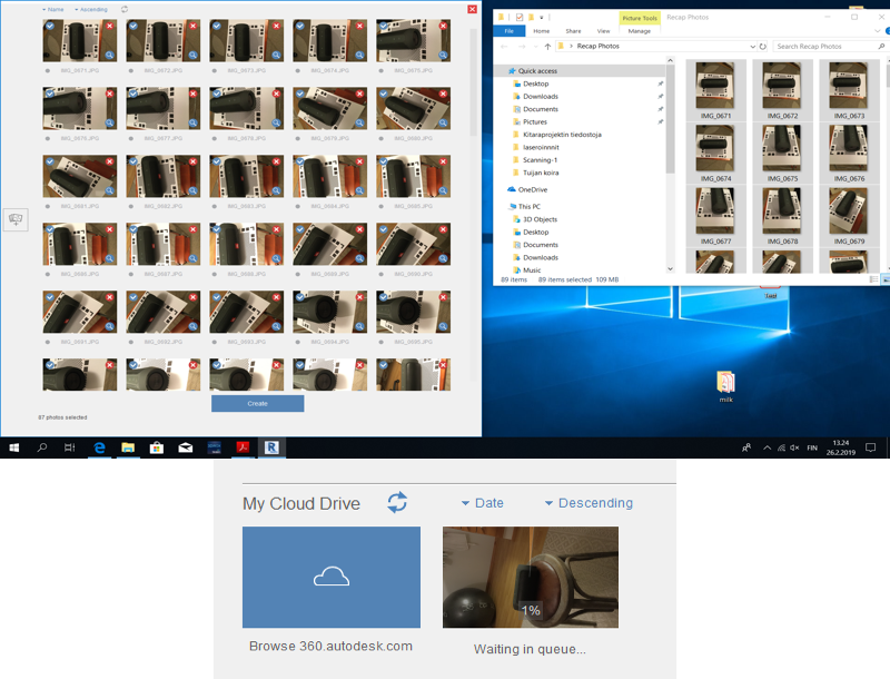
Autodesk Recap Photo
For Autodesk, I repeated the same process as explained above but took about 100 hundred photos of a Bluetooth speaker. When you open the application, from the main window you create an object which takes you to a window for uploading photos. You select the pictures and click on create. The processing time varies a lot and may range from 30 minutes to 3 hours or even more!
The final model was not as good as in Scann3D, though.
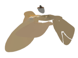
To clean up the file, I imported it to Fusion, switched to the MESH Workspace and deleted the unwanted faces.

Original Files
Click on the links to download the original design file()s:
Reflection
This was the first time I have ever 3D-printed or designed anything, so this week’s exercises were a welcome learning experience. Pretty much all the coming weeks will be a learning exercise as most of it will be new.
The printing and documentation was a bit delayed this week because we could only do the testing on Monday. As we sent multiple files to print (the test piece and our design), I did not get to properly test the functionality of each of the printers well, so this is something I plan to do again. For my design, Fortus had better finishing (after soaking the printed object for a few hours to remove the support material) than Formlabs. It was difficult to remove the support material from the Formlabs printed design especially those on the insides of the object. I will design a curved or circular object in future to see whether the finishing will better in the interior.
In scanning, Recap Photo has more advanced features than Scann3D but the model from the latter was clearer with fewer images. I followed the same process and took more pictures from multiple angles, but even with 3 tries the model was not good in Recap Photo. I will try scanning again later in ReCap or some other program.