11. Input devices
This week I worked on something related to the final project. I added a motion sensor to a microcontroller board and tested it. For the group work, we probed the analog and digital signals for a hall sensor.
Assignment
Individual task
Measure something: add a sensor to a microcontroller board that you have designed and read it.
Group task
Probe an input device’s analog levels and digital signals
Group Assignment
For the group assignment, I worked with Alok, Jobin, Sahan, and Yasir to probe a hall sensor’s analog and digital signals.
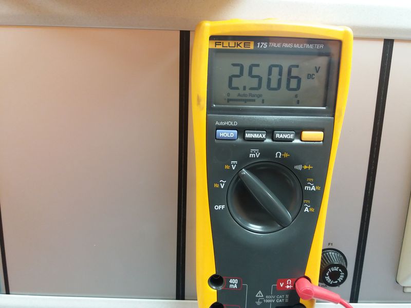
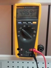
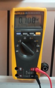
The sensor board was tested by directly powering it from a 5V power supply and measuring the resulting voltage.
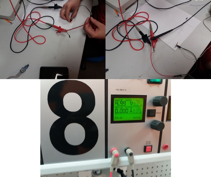
The output voltage when no magnet nearby was 2.5 V
When magnetic pole is close to the sensor the voltage went up to almost 5V.
When flipped, it dropped to almost 0V which confirmed that the sensor was working.
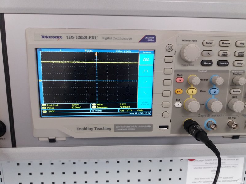
We also measured the digital signal with an oscilloscope by attaching the ground pin to the PCB ground and the positive probe to the transmit/receive pins of the ATtiny44.
When the the flip side of the magnet came close to the sensor, we got following signal from oscilloscope.
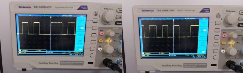
When the magnet was close to the sensor, we got the following signals.
And a video below.
Individual assignment
Designing the board
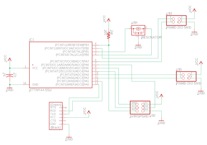
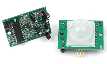
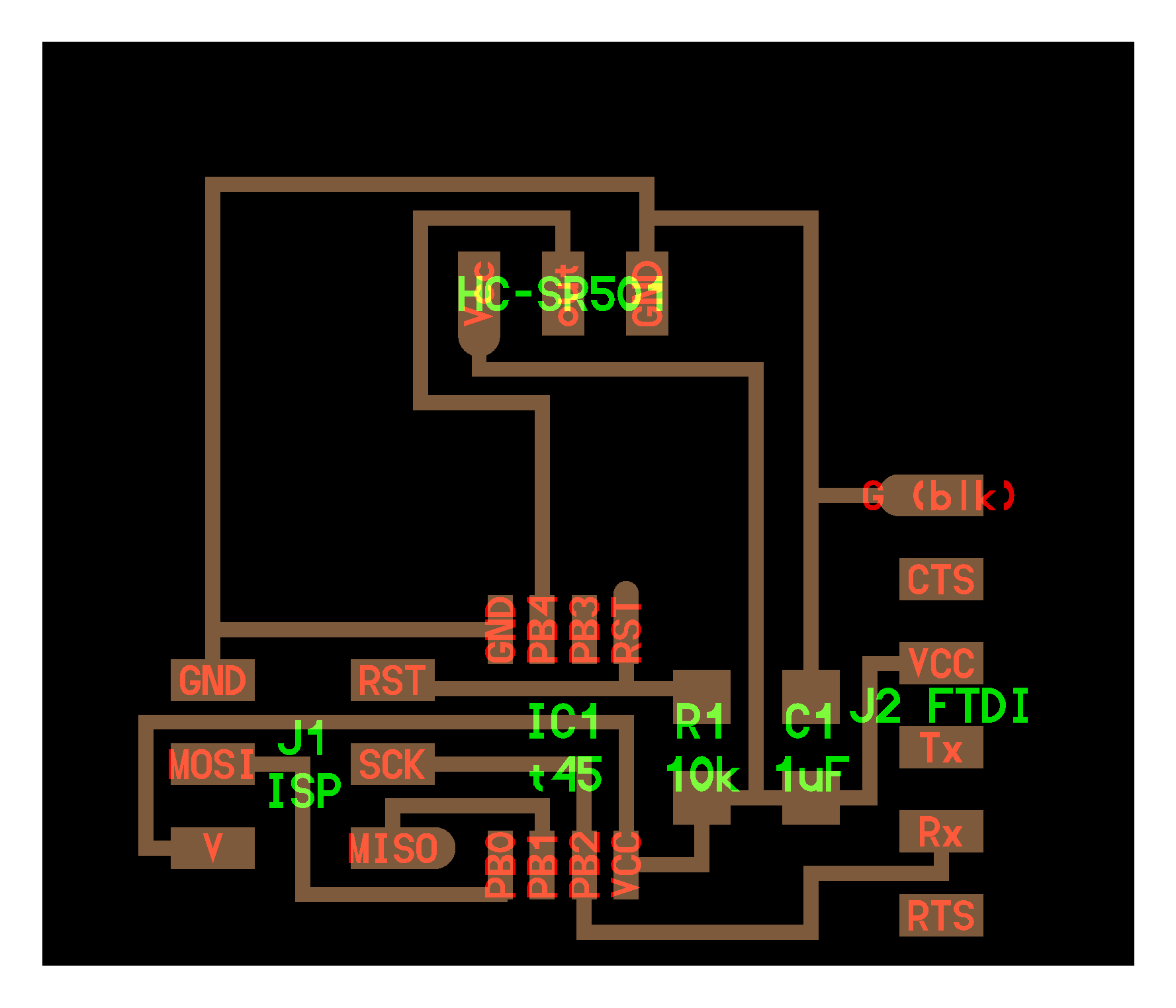
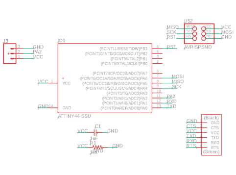
In this week’s assignment, I wanted to try a sensor that I am planning to use for my final project, so I decided to test the Pyroelectric (“Passive”) InfraRed (PIR) sensor. I reviewed Neil’s example in Input Devices and other examples online. I first started to recreate Neil’s board, but then I decided to modify the board from Electronics Design by removing the button and LED and adding extra 2x2 pin headers as outlined in Jari Uusitalo’s documentation for the same assignment in 2018.
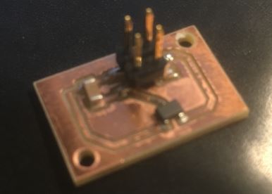
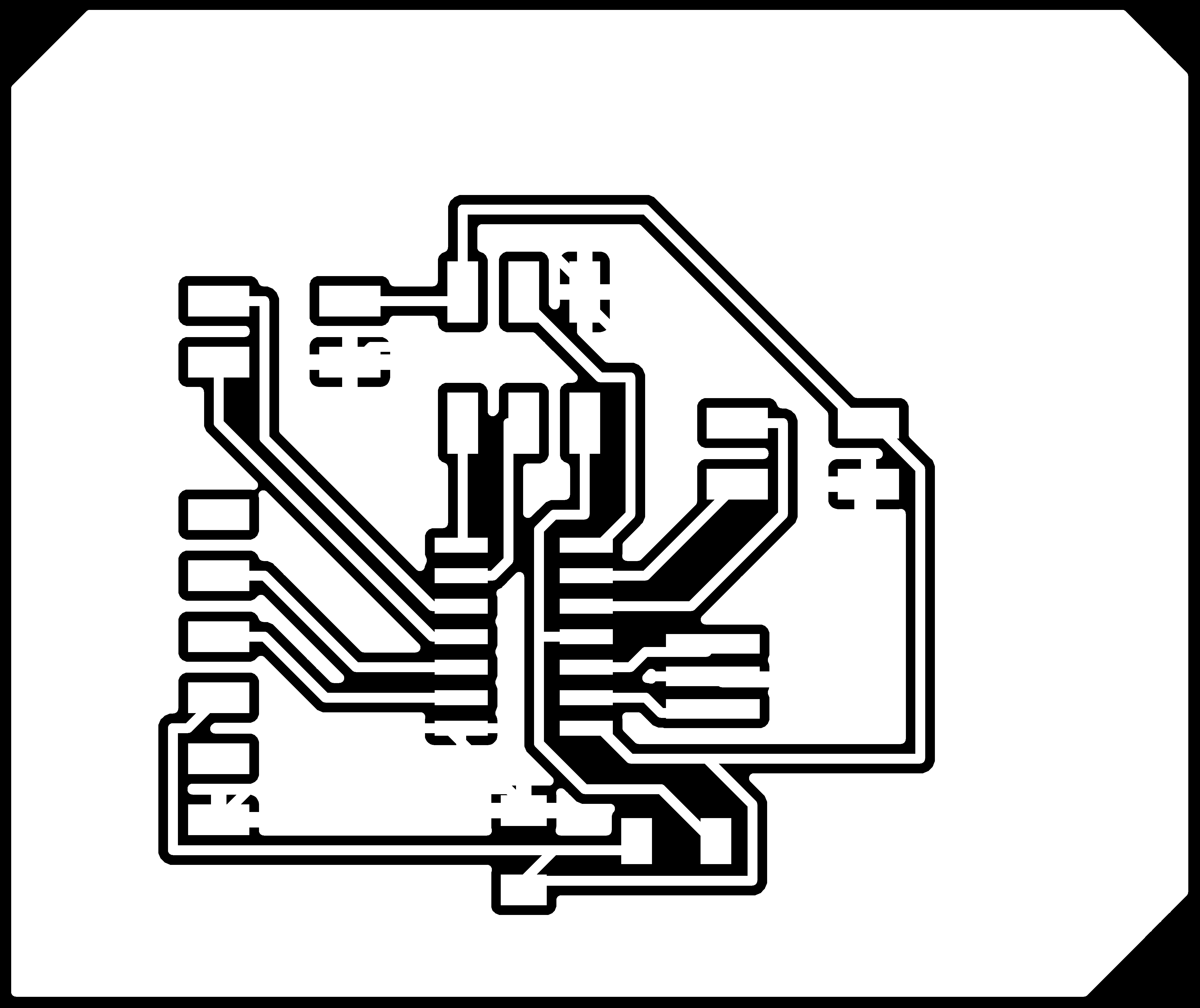
After a bit of trial and error, the board was finally routed.
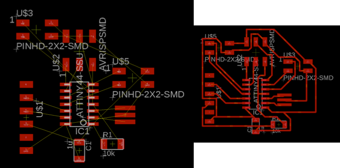
Following the process outlined in Electronics Design, when the Eagle board design was ready, I exported it as traces and outline PNG files. Then, I converted the PNG files for milling, milled the board with the Roland-SRM 20 milling machine, soldered the components and checked for continuity with a multimeter.
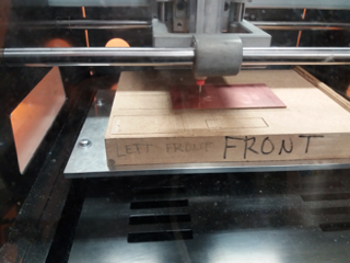
Milling process
Components
- 1x ATtiny44 microcontroller
- 1x 2x3 AVRISP programming header
- 1x 1x6 FTDI header
- 1x 1 uF Capacitor
- 1x 20 MHz Resonator
- 1x 10 kΩ Resistor
- 2x 2x2 Pin header
After a few challenges outlined in the reflection below, here is the final result:
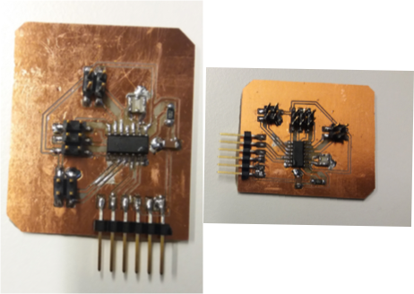
Not the best looking board and soldering job, but it worked eventually!
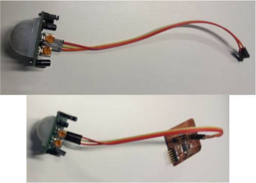
To attach the motion sensor to the board, I used 3 female-female jumper wires. I used 2x2 pin headers on the board because I am still not sure whether or not the PIR sensor will be the one I use in my final project.
PIR sensors allow you to sense motion, and are almost always used to detect whether a human has moved in or out of the sensors range. They are small, inexpensive, low-power, easy to use and don’t wear out.
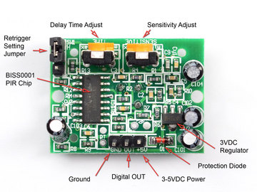
PIRs are basically made of a pyroelectic sensor, which can detect levels of infrared radiation. Everything emits some low-level radiation, and the hotter something is, the more radiation is emitted. The sensor in a motion detector is actually split into two halves. The reason for that is that we are looking to detect motion (change), not average IR levels. The two halves are wired up so that they cancel each other out. If one half sees more or less IR radiation than the other, the output will swing high or low.
Along with the pyroelectic sensor is a bunch of supporting circuitry, resistors and capacitors.
Programming the board
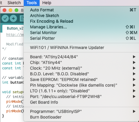
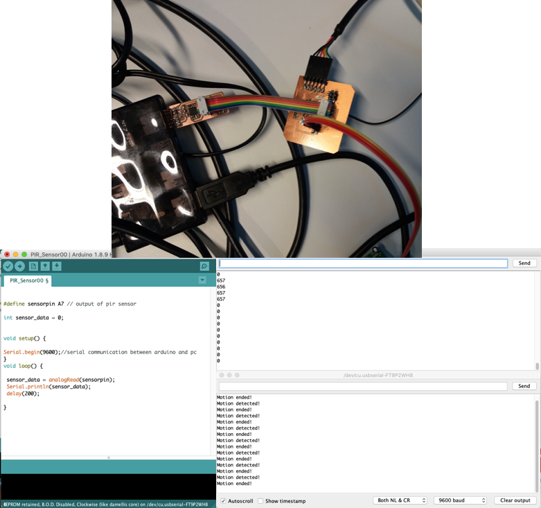
I programmed the board following the procedure I did for programming the hello world board in Electronics Design. Then, I used the Arduino IDE to program the board. As the settings needed to enable programming the ATtiny with Arduino were made in Embedded Programming, this was relatively easy.
I connected the digital out pin of the sensor to the connector attached to Pin 6 of the ATtiny which corresponds to pin 7 in the Arduino. Pin 6 according to the data sheet in p. 61 is:
- Port A, Bit 7 – ADC7/OC0B/ICP1/PCINT7
- ADC7: Analog to Digital Converter, Channel 7.
- OC1B, Output Compare Match output: The PA7 pin can serve as an external output for the Timer/Counter1 Compare Match B. The pin has to be configured as an output (DDA7 set (one)) to serve this function. This is also the output pin for the PWM mode timer function.
- ICP1, Input Capture Pin: The PA7 pin can act as an Input Capture Pin for Timer/Counter1.
- PCINT7: Pin Change Interrupt source 7. The PA7 pin can serve as an external interrupt source for pin change interrupt 0.
Then, I just connected the board via a USB hub to the computer, opened the Arduino IDE, and tested the PIR. I got the sample code below for testing the PIR on the Arduino from a project in GitHub.
// Uses a PIR sensor to detect movement
//

int inputPin = 7;               // choose the input pin (for PIR sensor)
int pirState = LOW;             // we start, assuming no motion detected
int val = 0;                    // variable for reading the pin status
void setup() {
pinMode(inputPin, INPUT);     // declare sensor as input
  Serial.begin(9600);
}
void loop(){
  val = digitalRead(inputPin);  // read input value
if (val == HIGH) {            // check if the input is HIGH
delay(150);
if (pirState == LOW) {
// we have just turned on
      Serial.println("Motion detected!");
// We only want to print on the output change, not state
      pirState = HIGH;
    }
  }
else {
delay(300);
if (pirState == HIGH){
// we have just turned off
      Serial.println("Motion ended!");
// We only want to print on the output change, not state
      pirState = LOW;
    }
  }
}
Second sample code
The image below outlines the process of connecting to the board and the output of the sample codes when motion is detected.
Files
- Arduino: Motion one / Motion two
- Eagle - Schematic / Board
- PNG - Traces / Outline
- RML - Traces / Outline
Reflection
Compared to some other weeks, this was to be a relatively smooth week as we only needed to try out an input device. The plan was to replicate Neil’s board for the motion sensor, which I started to do but after reviewing some of the previous years’ documentation for Oulu students, I reconsidered. Below is an image of the initial schematic.
It would be easier to just add connectors to a new board which would allow for different components to be connected to the board, rather than soldering a sensor on the board. I decided to replicate the board from electronics design week as mentioned above by removing the LED and button and replacing them with 2x2 pin headers. I decided to use the 2x2 headers even though the PIR sensor has 3 pins as I am still not sure whether it will be the one used in the final project. This wasn’t a problem as it was just a matter of referring to the right pin in the code for testing it with the Arduino.
The milling had to be done twice as in my confused state when preparing the files, the traces file turned out to be bigger than the outline. This delayed the process to the following day. When I came back the following day, the files were ok and the milling went well, but the soldering was torture. The third time certainly wasn’t the charm for me! There was a short circuit in the board and even after multiple rounds of testing with Ari during the first evening we couldn’t find the problem. It’s only when I came back the following day that we both realised that I used the wrong board and should have removed the top layer of the PCB before soldering.
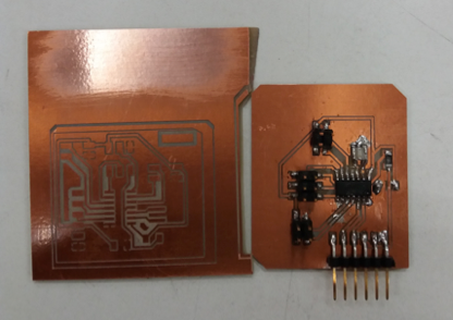
With Jari’s help, we managed to fix the board. The problem was underneath one of the connectors the VCC pin was connected to GND which Ari and I didn’t notice.