20. Project development
In this week, I worked on the finalising the project and details are outlined below. The main tasks for the week were to outline:
- what tasks have been completed, and what tasks remain?
- what has worked? what hasn’t?
- what questions need to be resolved?
- what will happen when?
- what have you learned?
Completed and remaining tasks
It really went down to the final weeks to get a concrete idea of how o implement the initial idea. The project idea has been the same from the beginning, but because I did not have time throughout the fab academy journey to properly work on it (there was and there is still plenty to learn!), it remained pending. That is until the final weeks.
I had started working on the main board for the final project in Output devices, but did not get the board ready then and could not revisit the work until the final weeks. Following the processes outlined in electronics production and design weeks, I fabricated the main board and it is now ready (finally!) for programming.
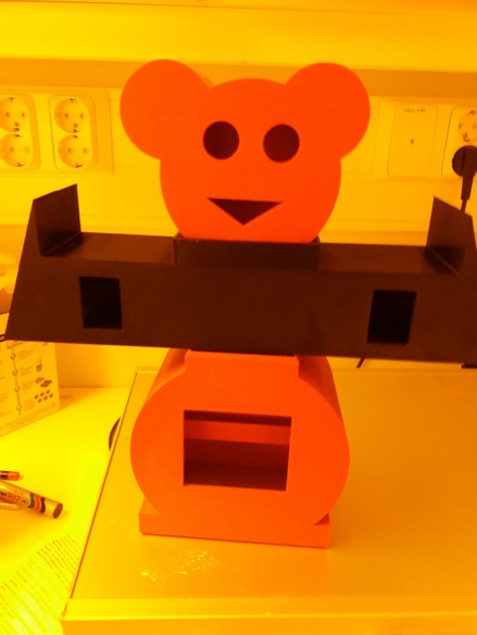
I also designed a logo in computer-aided design which I sandblasted on different materials in wildcard week. Later, I designed and 3D printed the moveBot following the processes outlined in 3D Scanning and printing. The design was 3D printed in Stratasys Fortus 380mc that uses ABS (Acrylonitrile butadiene styrene). I got the dimensions wrong for the different parts so I needed to 3D print additional support to hold them in place when attached. Also, for the arm, as it was using a lot of support material because it was a hollowed design, it was suggested to split the design in half which Mikko did by just splitting the STL file. Therefore, additional support came in handy as I didn’t need to glue the two halves together. The support held them firmly together.
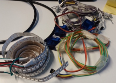
The different components (servos, IR LEDs and a buzzer) that are to be attached to the moveBot were prepared earlier and I have the LED strip that will be placed on the inside of the moveBot.
The main tasks left are programming the main board outlined in the next section, designing a bottom cover for the moveBot that will house the electronics, and a wider base that will hold the moveBot that should be done by 19.6.19, the final day for all presentations. I have less than a week to complete the remaining tasks.
The programming is ongoing from today (14.6.19) until the deadline if not sooner.
I will design and 3D print the bottom cover tomorrow (14.6.9), and laser cut the base for the moveBot either tomorrow or then on Sunday as Fab Lab will be open for a few hours then.
What has and hasn’t worked?
Even though, I have had the same project idea from the beginning, as I like to overthink, it took me a while to settle on the actual design. Initially, the idea was to design a human size (about 150 cm in length) object with movable parts with different kinds of LEDs that indicate the progress of activity, but as my design skills are not the best and was just getting reacquainted with Fusion, this took some time. As time was running out, I thought about parametrically designing a simple hollowed box-like structure that could be laser cut and attached. Finally, I settled on the scaled down 3D design.
There are no movable parts or joints which I thought to include, but as this is the first of what I hope will be a few iterations, other design features will be added to any future iterations of the same or some other projects. When designing the different components of the moveBot (the head, arms and body), I overestimated the size needed for each of them to fit properly when assembled and I had to, with Eino’s suggestion, design simple support that would ensure they are firmly attached together. The support component was also needed, especially for the arm which had a hollowed design, as it had to be split into two so that it would not use much support material when being 3D printed.
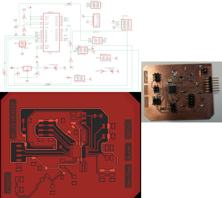
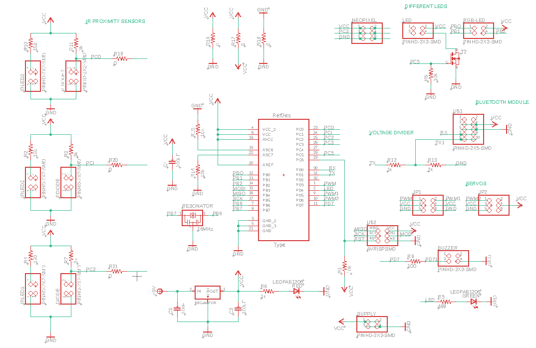
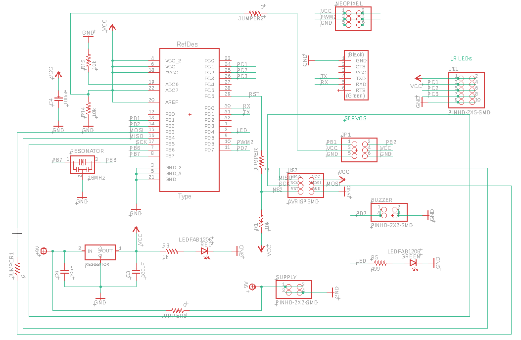
The most challenging part was the electronics design for the main board. Initially, the main board was to have numerous components as outlined in Output devices, but as I had challenges, the board had to be scaled down. I removed the IR LEDs from the main board, redesigned the one from Networking and Communication by removing the ATtiny44 and adding pin headers that will be used to connect it to the main board. The final board has 2 instead of 3 servos, 2 instead of 3 IR LED pairs, and just the Neo-Pixel LED strip instead of 3 different types of LEDs that were each to signify different levels of activity. I also left out the Bluetooth module as this needs a bit extra work and I am pressed for time (perhaps something for later).
Initial schematic design for final project board
 Modified final project board schematic
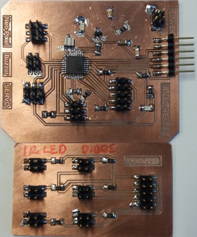
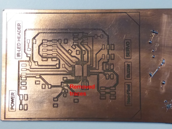
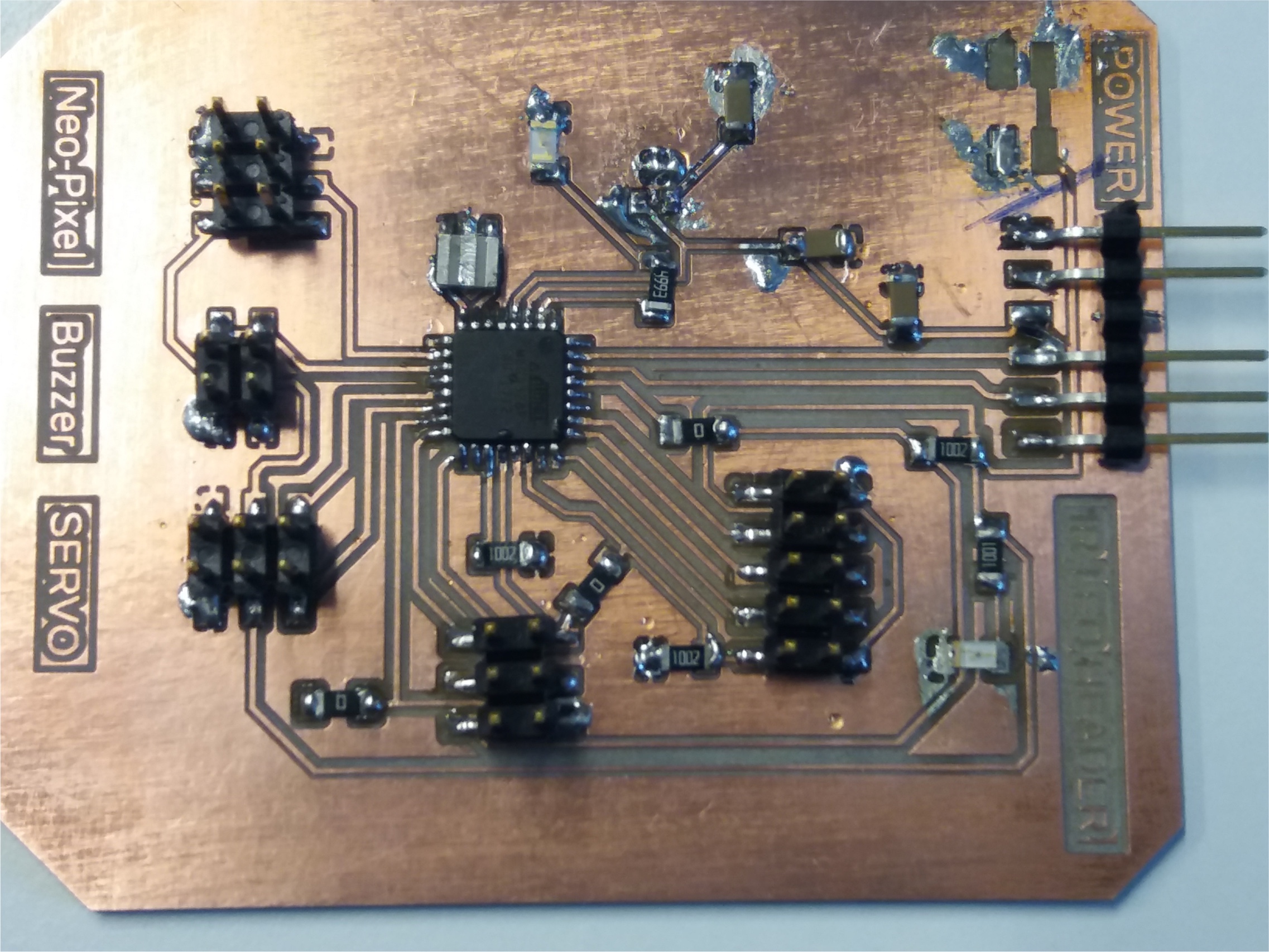
Complete boards
After ages spent routing in Eagle, finally managed to get the design files ready (or so I thought). For this final board, I wanted to try the laser-based PCB manufacturing that Perttu did in Wildcard week. The board almost turned out well, but some traces were removed and some were not done well.
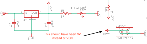
I decided to mill the board and then soldered it. After soldering, I checked that all connections were ok and there were no shot circuits with a multimeter. When trying to program, the board heat up and the regulator burnt.
The following morning, Antti explained that there was an error in my schematic design. I had connected the 9V input voltage to VCC of the power supply which caused the regulator to heat up when the FTDI cable was connected as it wasn’t receiving an input voltage.
We tried to fix the board by adding a jumper wire connecting the VCC pin of the power supply to 9V input pin of the regulator, but I ended up ruining the board and had to mill another one.
I made the corrections, prepared the design files and milled a new board. After soldering and checking that everything is connected, I burned the bootloader of the microcontroller as outlined in Embedded programming and will soon start working on programming.
What questions need to be resolved?
The main questions to be resolved now are programming (system integration) and assembly (finish quality). How the different components are controlled and the order of activities.
What will happen when?
Between today (13.6.2019) and Sunday (16.6.2019), programming, assembly of the different components and preparing the final project video and slide.
The deadline is the 19th of June but will try to finish before that as I am travelling on the 17th and will come back on the 19th to present. Preferably, most of the remaining tasks should be complete by Monday (17.9.19) morning latest.
What have you learned?
To paraphrase Antti M, good design comes from experience and bad design (or mistakes) are the path towards getting this experience! There is still plenty to learn, but I have a bit more knowledge about electronics design, I have improved my computer-aided design and embedded programming skills (although just a bit for the latter), the use of version control and overall project management.
On hindsight, and as mentioned a few times by Neil and the local instructors, doing something each week related to the final project would have saved plenty of time at the end. It wasn’t easy, though, as timing was always an issue and some topics were mostly new which needed their own time to process. I might not be using some of the processes covered in the program often, but it was good to learn about different processes of machine and mechanical design. Plus, it is amazing to realise how almost anything can be created in open and creative spaces as Fab Labs.