8. Computer controlled machining
Group Work
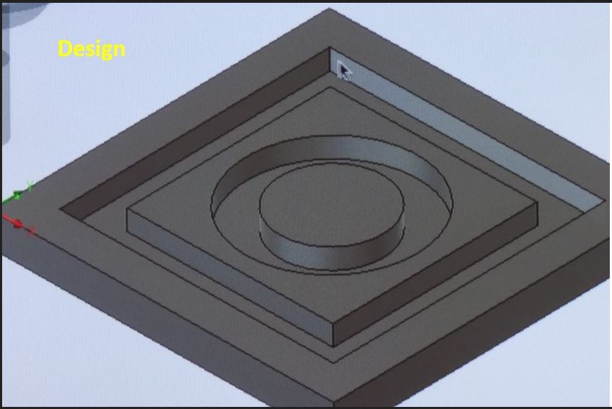
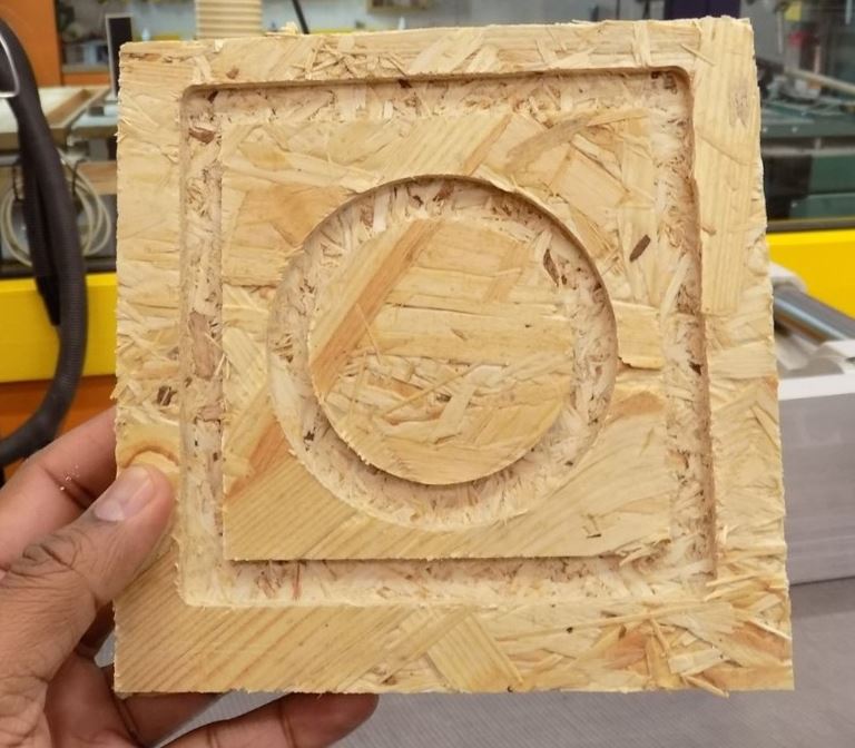
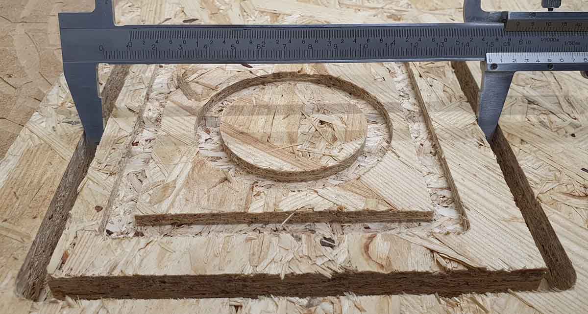
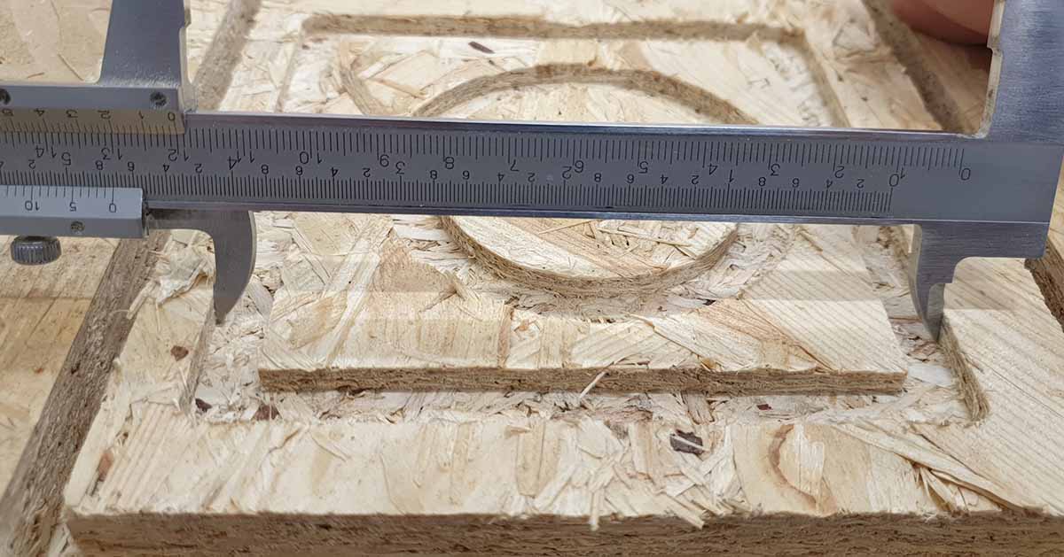
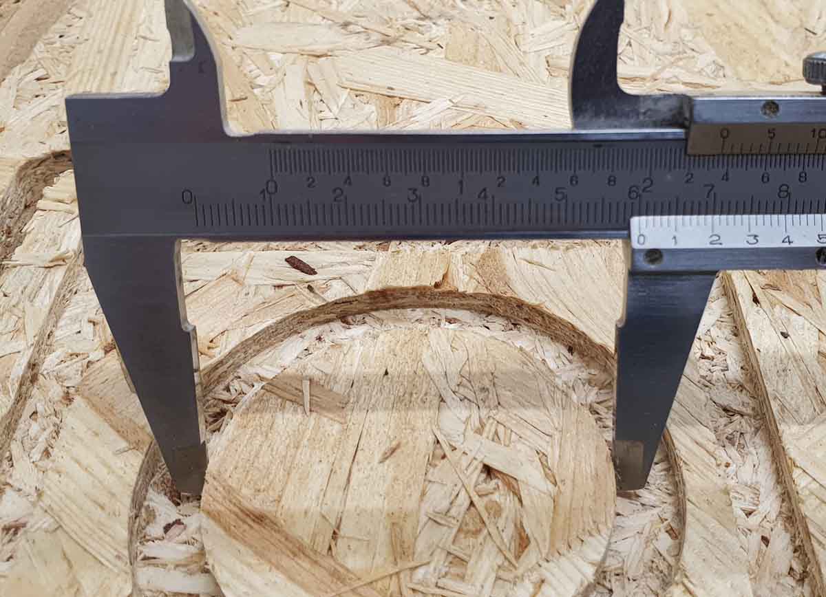
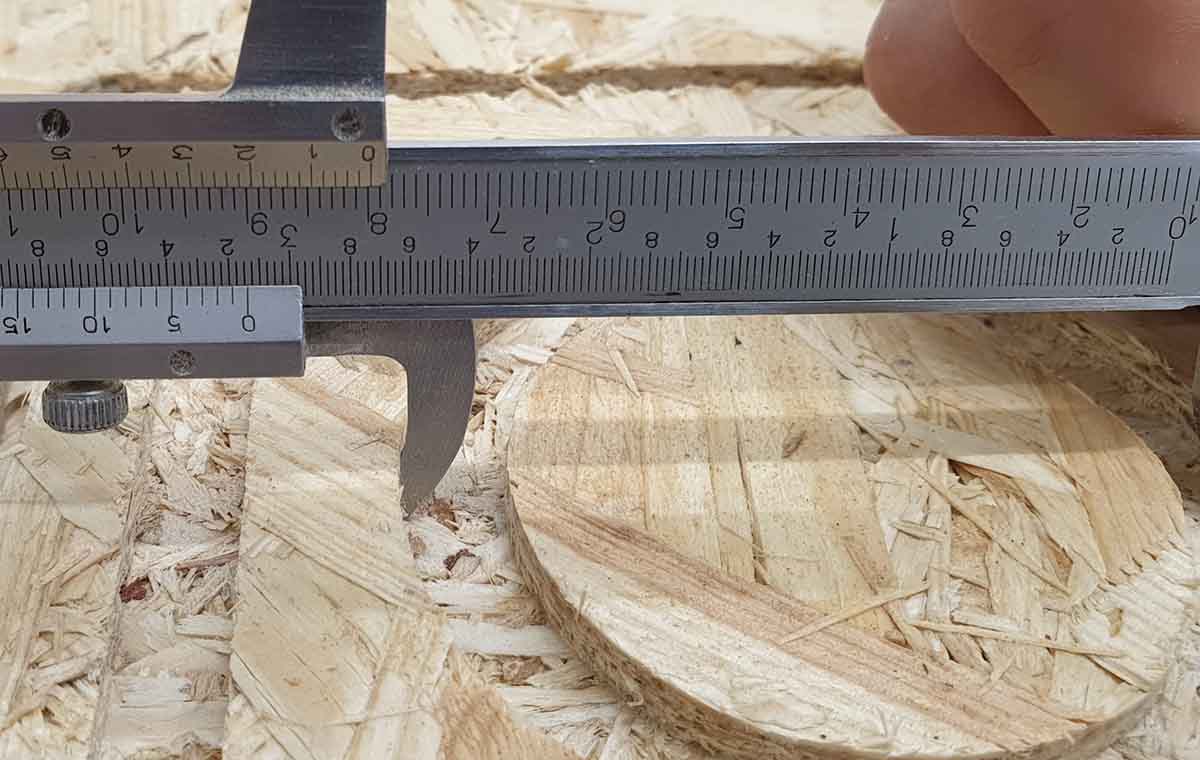
The Group work was done with the whole Oulu 2019 batch. All the picures and measurements related to the group work are taken from Jobin’s and Perttu’s page.
|
|
|
|
|
|
| Outer Square (mm) | Inner Rectangle (mm) | Outer Circle diameter (mm) | Inner Circle diameter (mm) | ||
|---|---|---|---|---|---|
| L1 | L2 | L1 | L2 | ||
| 150.11 | 150.10 | 120.31 | 100.14 | 80.11 | 59.88 |
| 149.92 | 150 | 120.08 | 99.99 | 80.15 | 59.92 |
| 150.42 | 150.01 | 120.05 | 99.86 | 80.09 | 59.85 |
| 150.10 | 150.01 | 120.13 | 100.03 |
79.70 |
59.76 |
| Average: 150.14 | Average: 150.00 |
Average: 120.14 | Average: 100.00 | Average: 80.01 | Average: 59.85 |
Individual Assignment
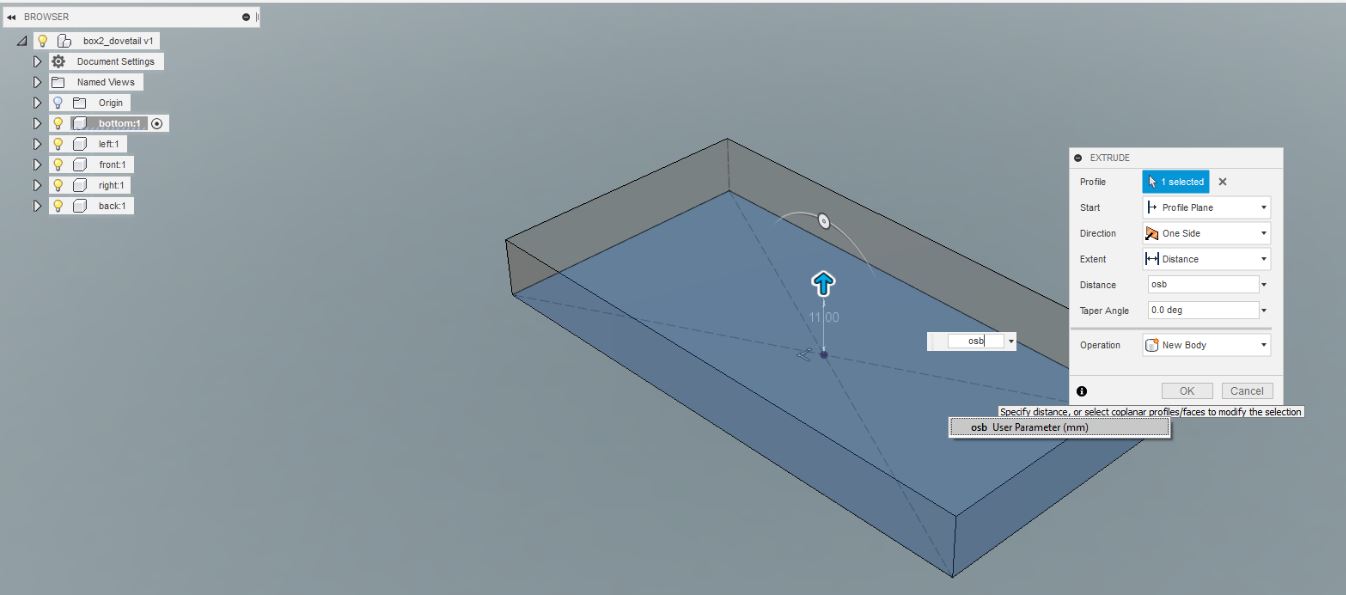
This week I designed a box with a lid to store things (how creative). I started with high hopes of making a fully parametric design with dovetail joints. It turned out that making a parametric design does not mean just specifying the needed dimensions as parameters, you also have to make sure that all the sketches are properly constrained with the defined parameters and all the references are from correct place(faces,edges…). I learned this the hard way. Furthermore, the dovetail joints I designed were blind and I didn’t use any T bone or dog bone structures, which meant that I would have to use lot of elbow grease to make the joints fit. And Monday is already gone and now I have to redesign my box with rectangular joints.
Examples
For designing, I followed the following videos on youtube and Heidi’s page.
Design Procedure
3D design
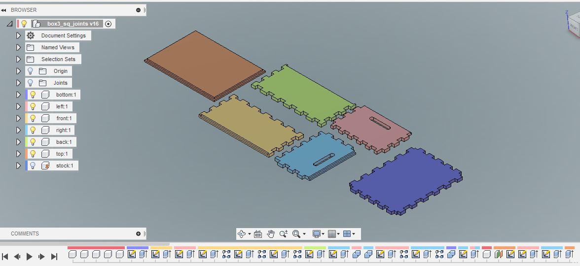
I started the design by defining all the components that will be assembled (bottom, left wall, right wall, etc.). Each component is very simple and just uses a rectangle and an extrude feature.
|
|
- I selected assemble –> Joint
- I selected the bottom face of the top of the component
- I selected the top face of the stock
- I picked the top face of the stock
- I selected “planar” for the type
- and then I pressed “flip” to get the blind pockets facing up.
This was repeated for all the components. To make sure that the components do not lie on top of each other, they were moved too by giving each of them a different X and Y offset.
|
Dogbones
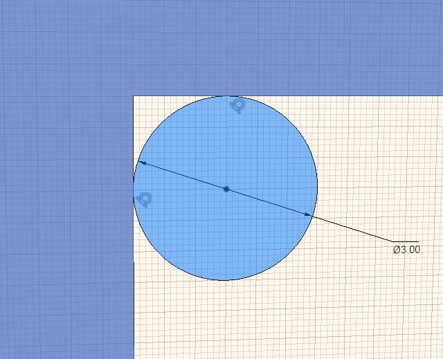
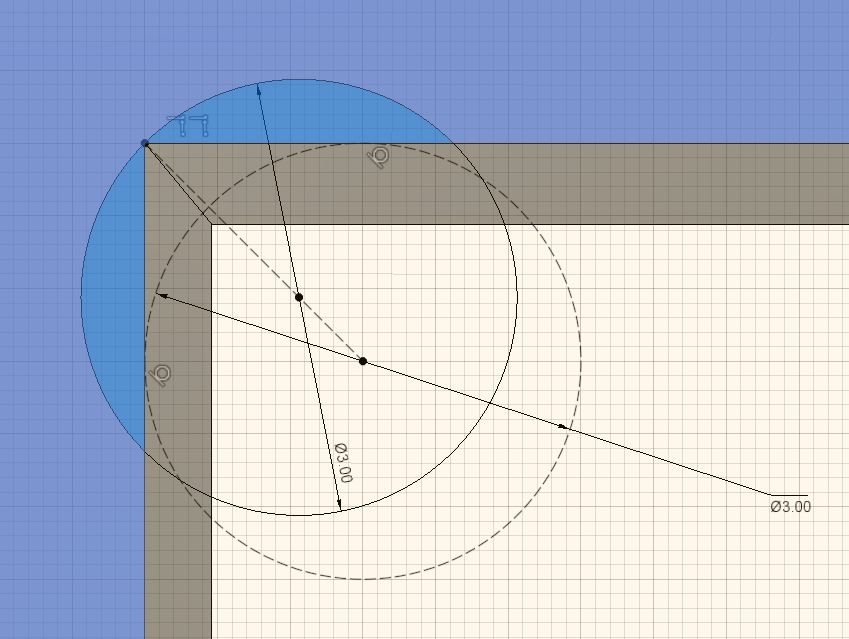
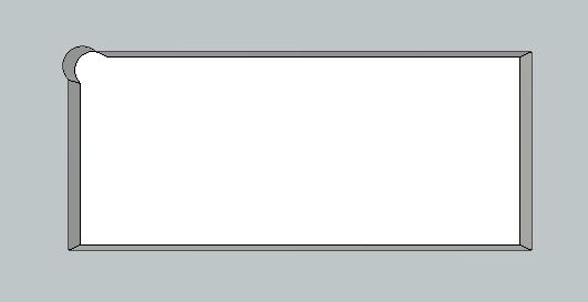
CNC milling tool bits are large in size compared to a laser beam (few mm compared to um). This creates a problem when one wants to cut right angles on an inside edge. The round bit cannot reach inside corners, thus some small amount of material is left. Check this webpage for visuals. To fix this issue, one can make extra cuts in the design so that the round mill bit can go a little bit closer to the edge. When done on a pocket, the resulting pocket looks like a dog bone and thus the name. Keep in mind this is only in design i.e., a rectangular pocket looks like a dog bone to the CNC machine but after machining it will look like a rectangle.
The easiest way to do it in Fusion 360 is by using the Dogbone Plugin. Unfortunately, when I ran that plugin on my design, it crashed. However, it is not very tedious to make them manually, if kept in mind while doing the design. For my next project I will definitely keep this in mind. Below is shown how to draw a dogbone on one side of a pocket
For manually making a dogbone, first create a circle which has the same diameter as the tool. Then create a construction line from the edge of the corner to the center of the circle. Next, create another circle with the same diameter and make the center of it coincident with the construction line created previously. Next, make sure this new circle touches the edge of the corner where one wants to create the dogbone. Next, extrude away the extra parts (the deep blue parts in the second image below). The example file is attached below.
|
|
|
Nesting
According to wikipedia
In manufacturing industry, Nesting refers to the process of laying out cutting patterns to minimize the raw material waste.
In my design, I have done the nesting manually where I manually placed all the different parts of my box on the ground stock. However, doing it manually is not the most efficient way and there is a Nesting Plugin for Fusion 360 which can be used for doing the same.
CAM settings
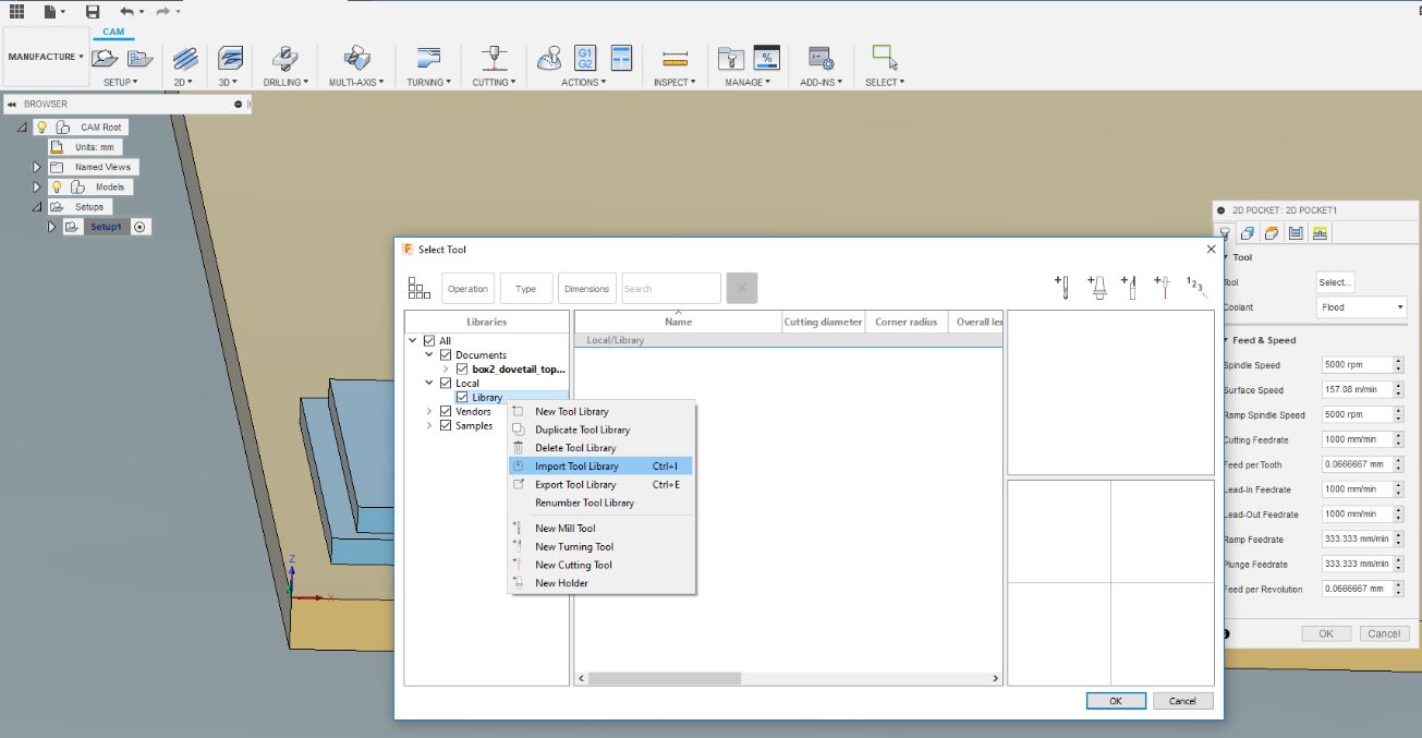
For creating the tool paths for milling, I downloaded the CAM processor file and the setting files with values for different milling bits (included below) from the Fab Lab Oulu Wiki site and added them to the Fusion.
|
Setup
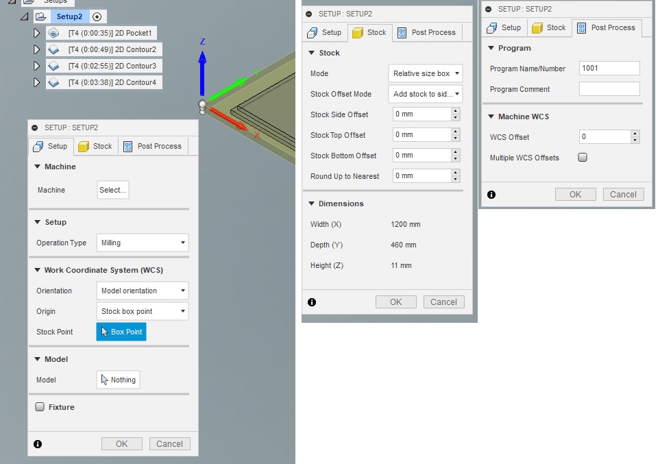
In the Fusion’s manufacture workspace, I created a new setup via SETUP>New Setup, where Operation type, Orientation, Origin, and Box point were set under the Setup options. Under Stock options, I changed all the offset values to 0mm. It is important to ensure that the Height (Z/vertical axis) is the width of the actual board that will be milled.
|
Pocket
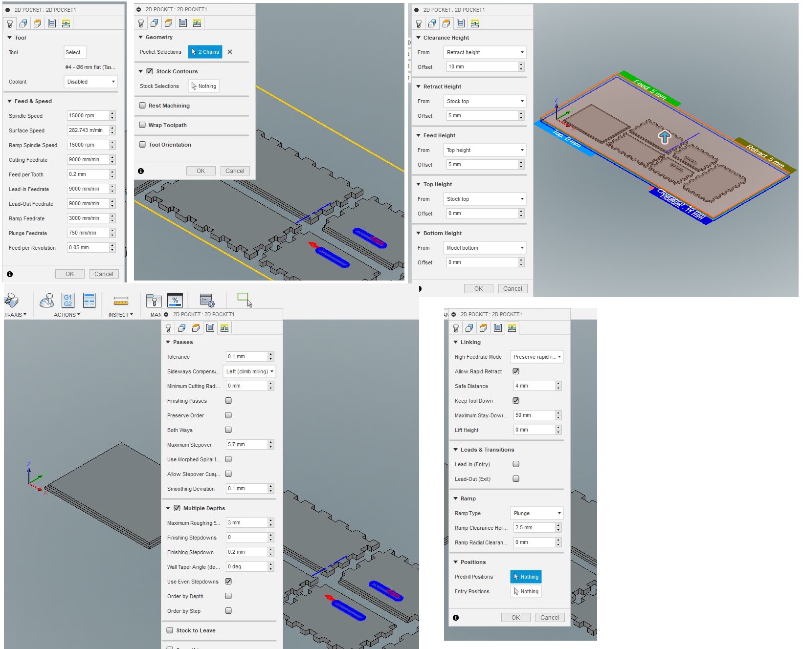
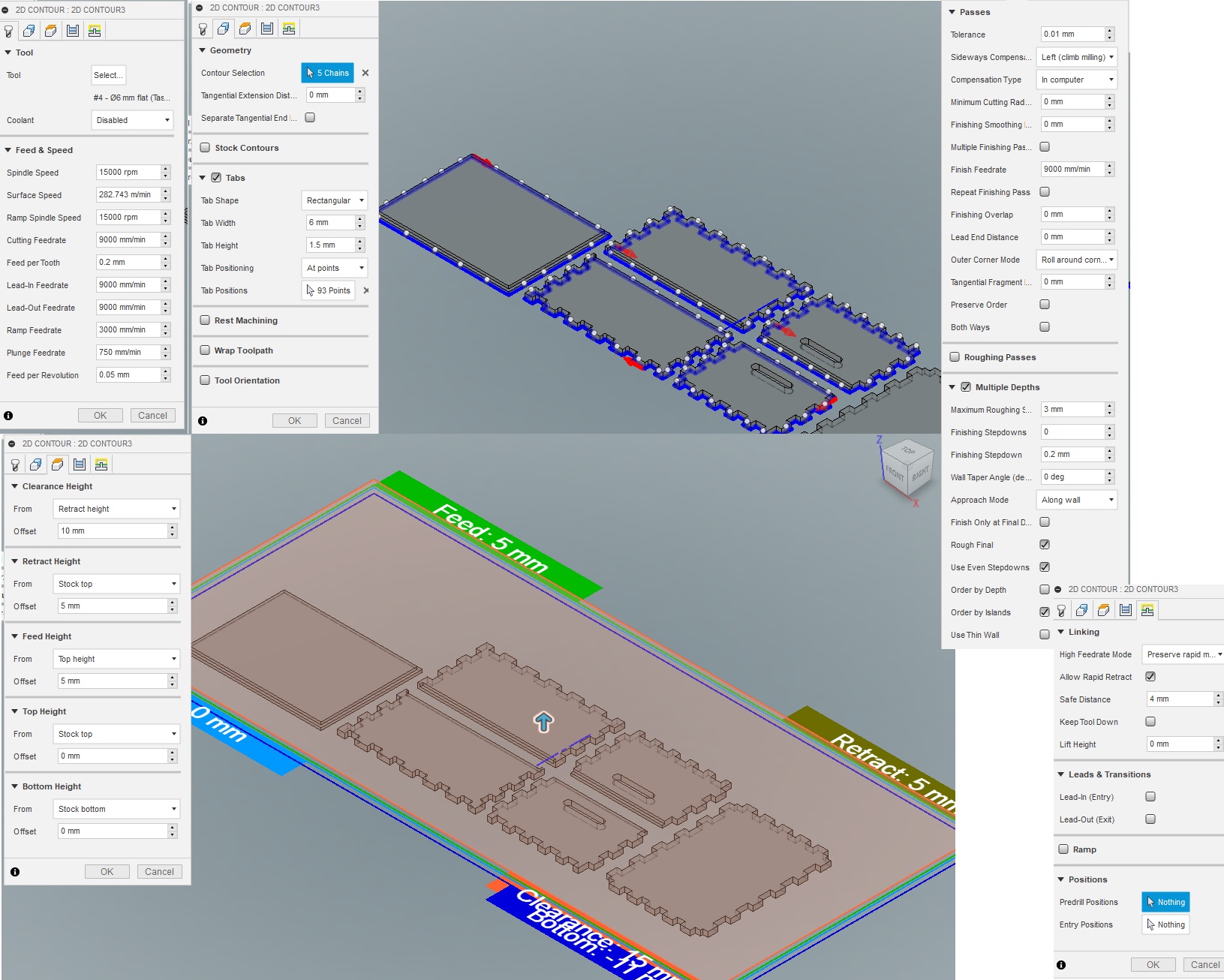
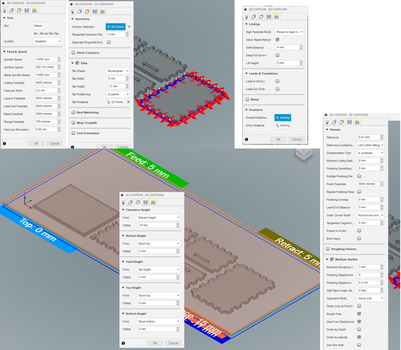
Under 2D>2D Pockets dialogue box in the Tool tab, choose the milling bit, which is the 6 mm flat bit. Under Geometry tab, select the areas where you want to make tabs/pockets. Under the Clearance Height tab, set the top and bottom heights. In Passes tab, set the maximum depth for drilling using even step downs. Under Linking tab, deselect Leads and Transitions and set the Ramp Type to Plunge.
|
2D contour
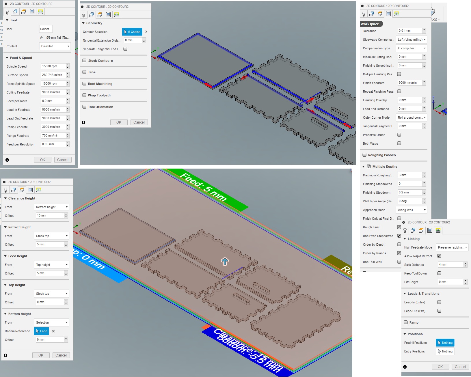
To make half depth slots, I used 2D>2D Contours. Most of the settings were similar to those in the 2D pockets, with only difference in the Bottom height under the Clearance tab.
|
2D>2D Contours was also used to cut the rest of the parts. Here too the only different setting was the Bottom height under the Clearance tab, which was set to Stock Bottom.
|
|
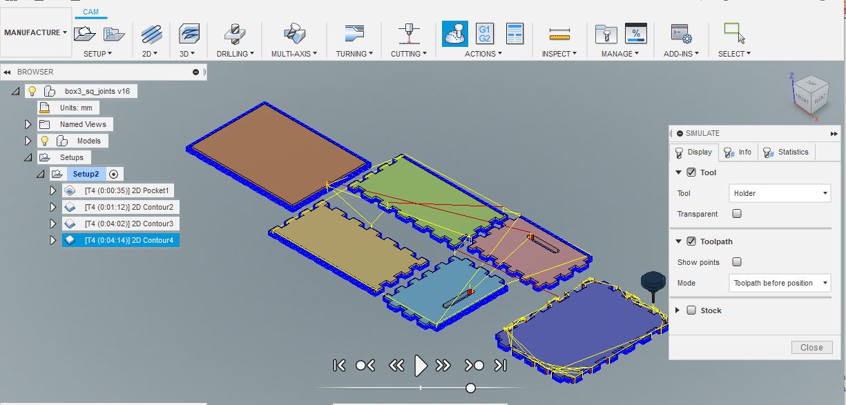
Simulation and file generation
After making all the tool paths, the tool paths were simulated to check any abnormalities. After that the post processor file was created which is required by the CNC router.
|
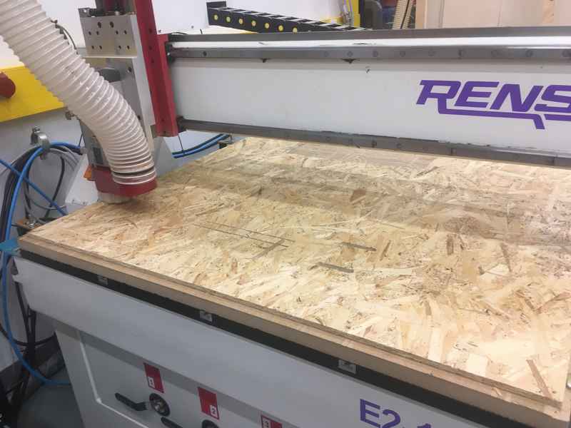
Cutting
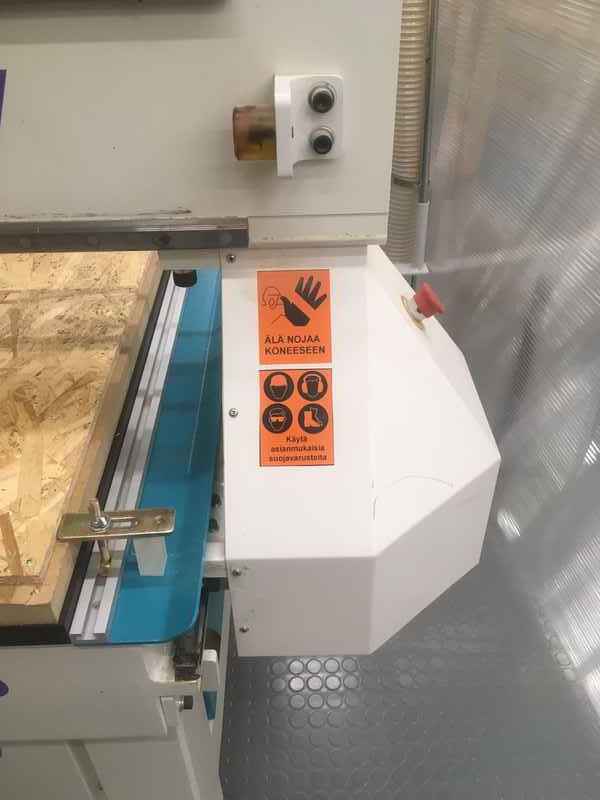
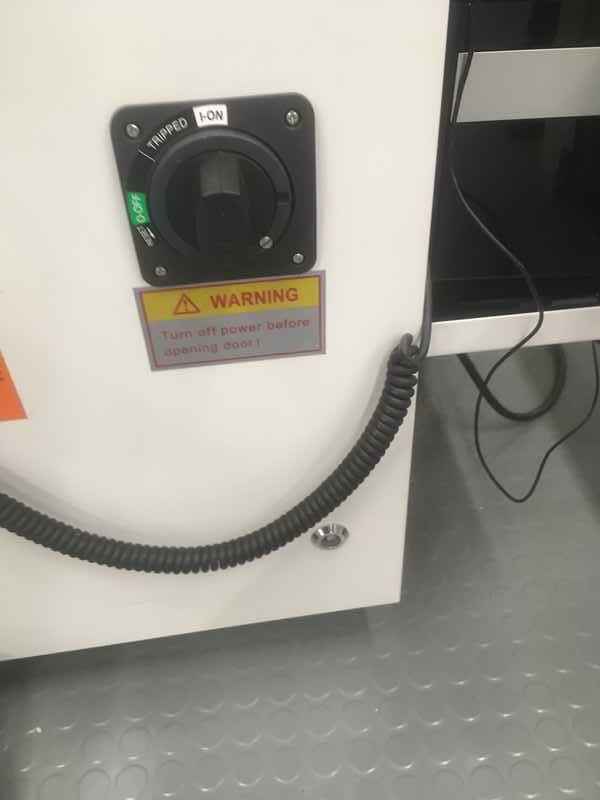
The CNC machine used is RE2-1325 CNC Router With Linear ATC. Below is a picture of the warning labels on the machine.
|
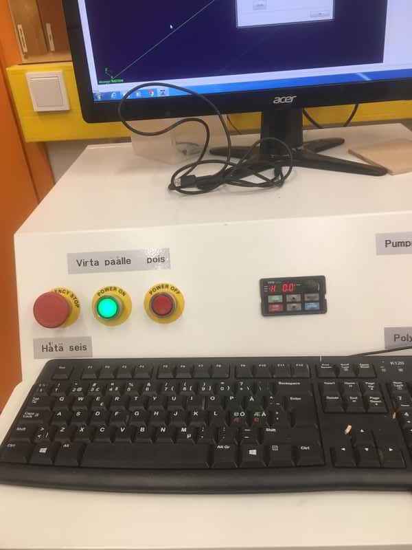
First you turn on the computer connected to the CNC machine, then the machine’s power switch and main switch are turned on.
|
|
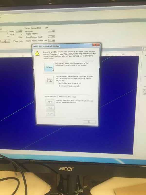
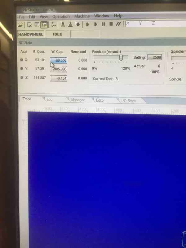
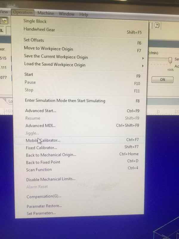
On the computer, start the NC Studio program, and then reset all the axis so that the machine knows the limit of the xyz axis.
|
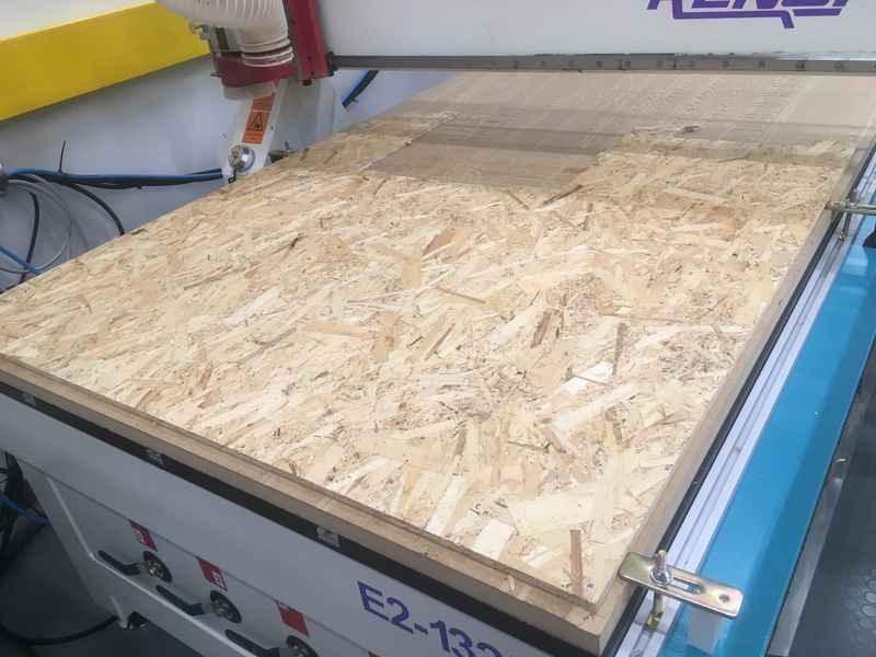
Next, place the material board with screws on the sacrificial surface of the CNC machine.
|
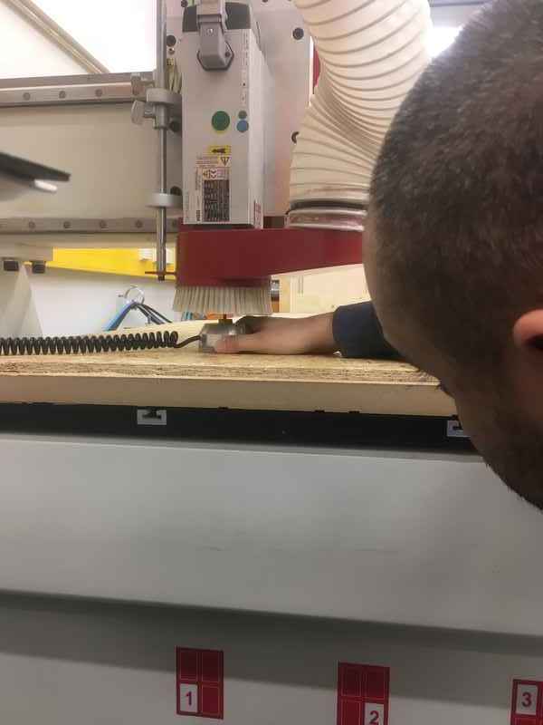
Next, place the desired milling bit in the CNC tool collet and placing the collet clamping nut followed by tightening them using a spanner.
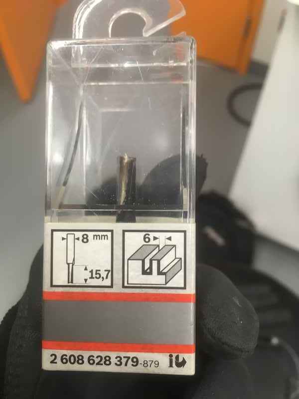
|
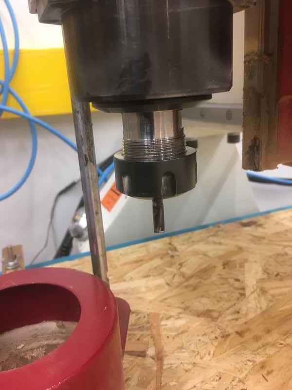
|
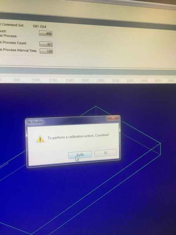
This is followed by setting the X and Y axis and calibrating the Z axis. Automatic calibration in the NC studio program was used for the Z axis.
|
|
|
|
|
|
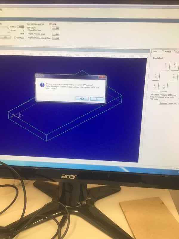
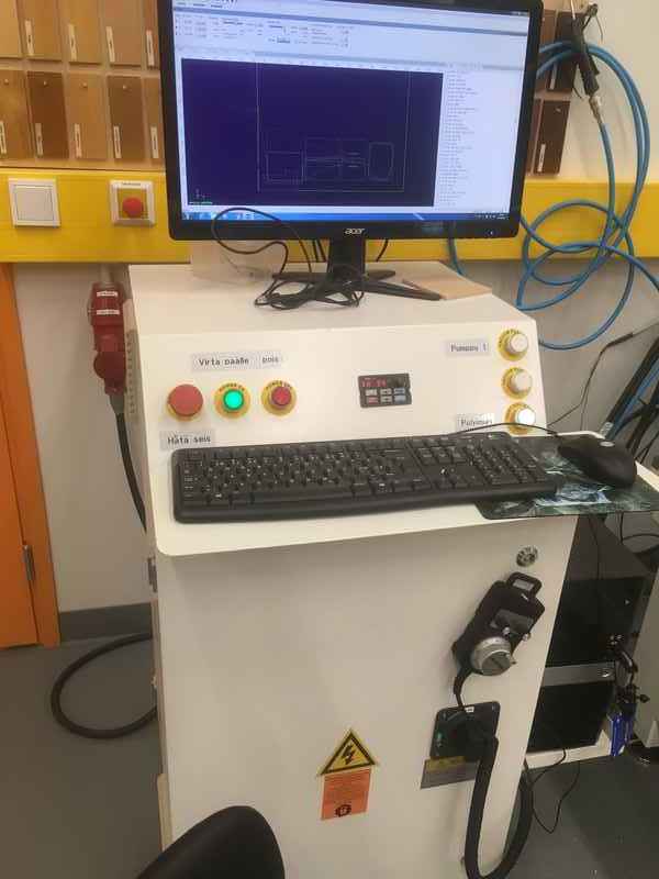
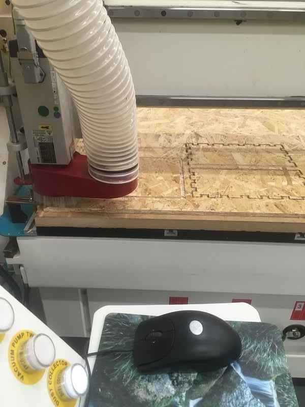
Load the .nc file on NC Studio program and simulate it.
|
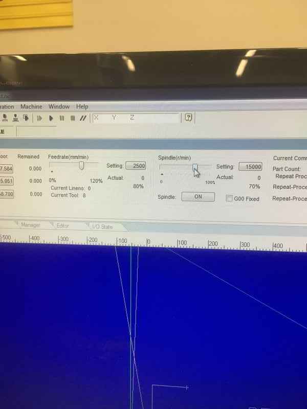
To start cutting, first switch on the vacuum pumps and the dust collector and then press PLAY. Keep the spindle speed to roughly 70% when starting the cutting.
|
|
|
|
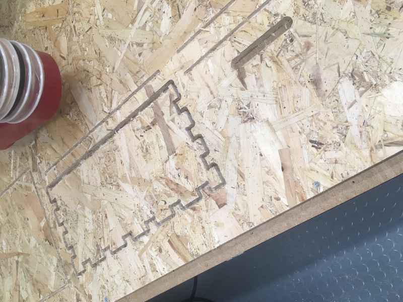
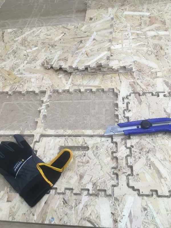
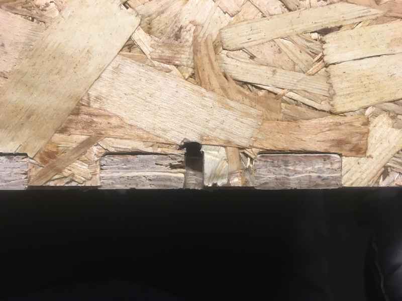
When the material is cut, switch off all the units. Use a knife to remove the tabs.
|
Assembly
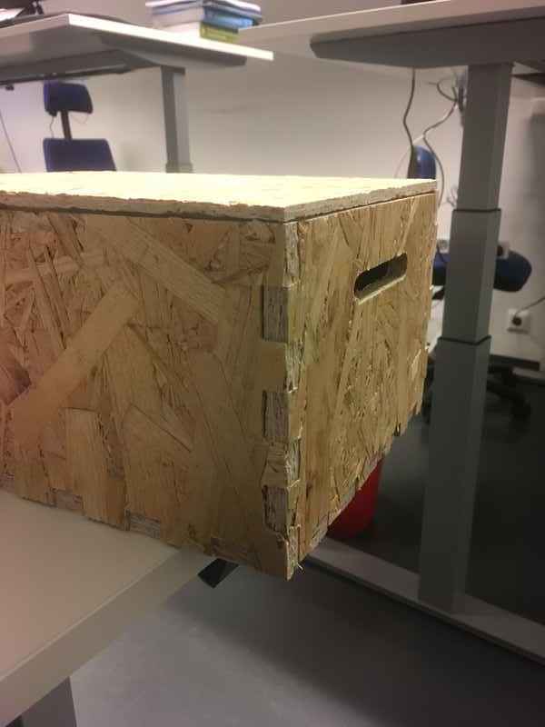
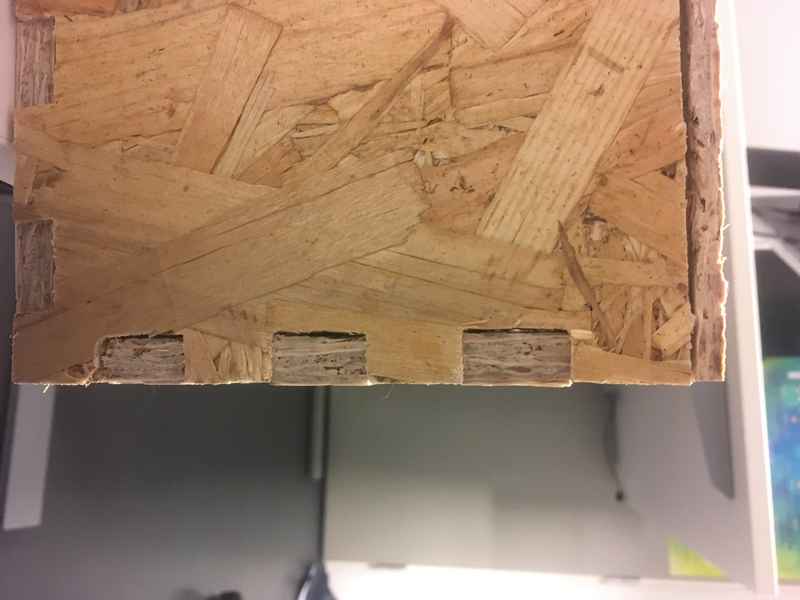
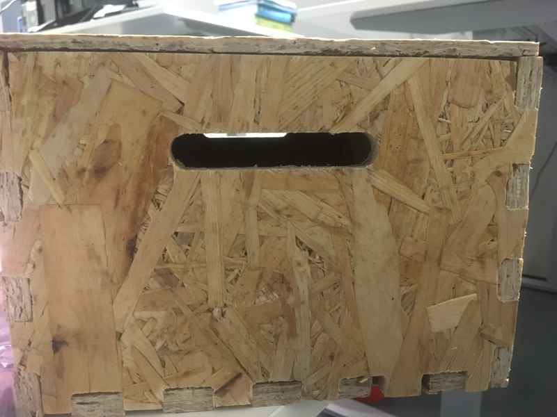
After some sanding and filing the edges and tabs, I assembled the complete box. Given the fact that I haven’t used any dogbones, some elbow grease was required for sanding and hammering in order to fit the panels which explains the tight fit. Furthermore, given the fact that the material used was an OSB board which chips really easily, finishing was not the best.
|
|
|
|
Speeds and Feeds
| Process | Speed (rpm) | Feed Rate (mm/min) |
|---|---|---|
| 15000 (max) | 9000 (max) | |
| 2D contour | 15000 (max) |
9000 (max) |
| Actual values at the router |
10500 - 12000 | 2500 |
Problems
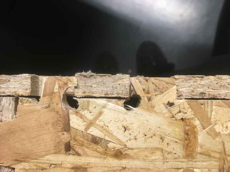
For some reason, while generating the tool path for the bottom part of the box, instead of one continuous contour, there were multiple contours and I was not able to automatically select all of them via the chain selection, so I had to manually select them. However, while doing so, I managed to skip some of the contours, which made the shown holes on the bottom plate.
|
|
Files
- Design (stl)/(fusion)
- Dogbone example (fusion)
- Tool Paths
- Tool Library
- Post processor file