4. Computer controlled cutting
This week I worked with laser and vinyl cutters. We used an Epilog Laser cutter and defined different settings for cutting.
Safety
Laser cutter has the potential to burn down the building and cause bodily harm, so please go through the safety instructions thoroughly. The manual can be found here.
The most important safety instructions are copied below from the manual.
- Stay with the laser. Never operate the laser system while unattended.
- Keep the area clear. Clean around the machine and keep the area free of clutter, combustible materials, explosives, or volatile solvents such as acetone, alcohol, or gasoline.
- Be prepared with a fire extinguisher. Always keep a properly maintained and inspected fire extinguisher on hand.
- Use Air Assist. Always use the system’s Air Assist feature when vector cutting.
- Use caution when vector cutting. Many materials have the potential to suddenly burst into flames when cut with a laser – even materials that may be very familiar to the user. Always monitor the machine when it is operating.
- Clean the laser. A buildup of cutting and engraving residue and debris is dangerous and can create a fire hazard in its own right. Keep your laser system clean and free of debris. Regularly remove the Vector Cutting Table to clean any small pieces that have fallen through the grid.
Laser settings
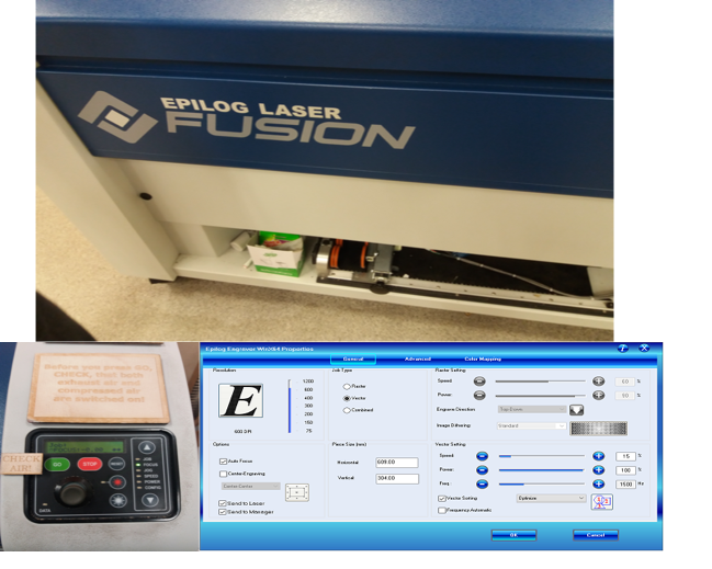
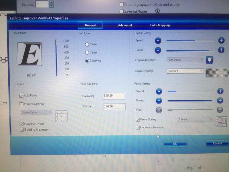
The image below shows the laser cutter, its control panel where you set the origin and position the cutter, and the different settings on the computer for defining the cutting parameters when sending a file. The settings differ depending on whether one is:
- engraving (raster - created with pixel-based programs),
- cutting (vector - created with vector-based software that is focused on drawing shapes and their outline), or
- both (combined) (described below).
In the dialog box for printing under advanced settings, you can also choose the material for printing. These include cardboard, MDF, acrylic of different thickness which are defined in the program.
|
The basic work flow includes the following things
- Make sure that AIR VENTILATION is ON.
- Place the material on the laser bed.
- Set the origin
- Set the laser focus (use auto focus for machines which have auto focus capabilities)
- Send the job
For setting the origin, choose JOG from the dashboard. Use the red laser button on the dashboard in order to see a visible red dot above the material showing the current origin. Use the joystick to move the origin(laser head) around to the desired location and the press the joystick to set the origin. The origin corresponds to the top left corner of the design file.
For setting the focus, choose FOCUS from the dashboard. Set the correct distance between the laser and the material. Adjust the distance by using the triangle shaped manual focus gauge placed on the laser head. By moving the joystick, move the material bed up and down so, that the focus gauge will just touch the surface of the material. Push the joystick to lock in the focus setting. Remember to remove the focus gauge from the laser head after setting the focus.
Send the job from the control PC and select it from the dashboard. The display will show an estimated cutting time of the job. Press GO to strat the job.
An interesting note about the CO2 laser from the manual
The CO2 laser beam itself is invisible and operates at a wavelength of 10.6 microns. The beam is about half the diameter of a #2 pencil. Unfocused, it will just make an ugly burn, leaving lots of charred material behind. The focus lens gives the beam an hourglass shape. At the center point the energy density is concentrated, allowing the very precise and clean material removal that is characteristic of laser engraving. The center of the hourglass is the focal point. The laser beam path is completely enclosed within the cabinet.
Group Work
In the group work we tried to measure the Kerf of two materials using laser cutter and also played a little with its settings for cutting and engraving. It was done in collaboration with Michael Oduor and Arash Sattari
Kerf
depends on many parameters, to name a few
- thickness of material, cause thicker the material more power is needed
- type of material
- type of laser
- focus of the beam
- speed of cutting
- power of the laser
- frequency of laser
so, assuming we are moving the laser along the path defined in the vector graphics file and the laser beam has a cutting diameter of K (kerf), then half of the kerf k/2 will be taken away from left side material and half from the right side. so if we are creating a hole, it will be bigger by K along one dimension.
In the end when it comes to kerf, the best rule of thumb is, “insides in, outsides out”. ‘Which means that to make a proper fit, to take kerf into consideration. Internal holes need to be made that much smaller, and outside sections need to be made that much bigger. [source]
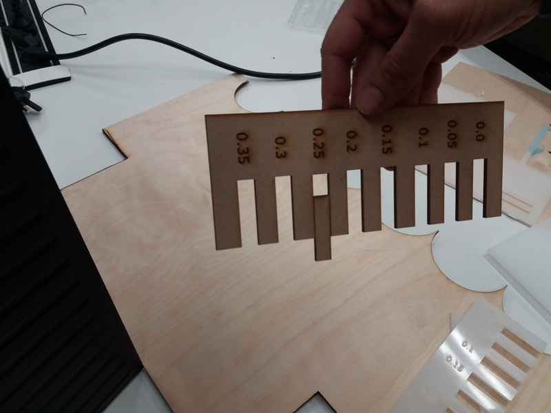
First Kerf Test
To make the test parts we designed an image in Inkscape with eight slots of varying sizes that were equally positioned across a rectangular diagram. The width of each slot was 10 mm minus the number indicated on the base of the slot. We had another rectangular piece 10mm wide and this was used to measure the kerf. We tested this piece with the different slots to see in which one it fits. We considered half of the number below the slot as the kerf for the laser cutter machine for the type of material we used.

|
|
We did the test with 3mm MDF material and 3mm acrylic. The kerf for MDF was 0.125mm and the kerf for acrylic was 0.175.
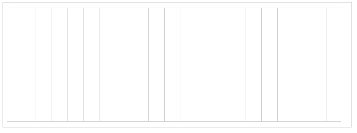
Second Kerf Test
In the second test for measuring kerf, we cut 20 lines in the material and then measured the difference between the hole and the combined width of the removed pieces. Below is the image of the graphics generated in inkscape. This yielded 19 free rectangles which were then measured and then compared against the hole left. Kerf was defined as (WH - ∑WPi )/20 . The files can be downloaded from here.
|
|
The measurements were done on the main laser on 2 materials (3mm acrylic and mdf) and on the mini epilog laser on 3mm acrylic. For the smaller epilog laser, the frequency was varied. No settings beside the material profile, were changed on the big laser machine. Below are the measured results (data)
| Material | Kerf | Parameter/Description |
| 3mm Acrylic | 0.1215 | Big laser (Epilog Fusion Laser Cutter), default parameters |
| 3mm MDF | 0.1275 | Big laser (Epilog Fusion Laser Cutter), default parameters |
| 3mm Acrylic | 0.274 | Small laser(Epilog Laser mini), Frequency 1500 |
| 3mm Acrylic | 0.2665 | Small laser(Epilog Laser mini), Frequency 500 |
| 3mm Acrylic | 0.225 | Small laser(Epilog Laser mini), Frequency Auto |
Cutting and Engraving
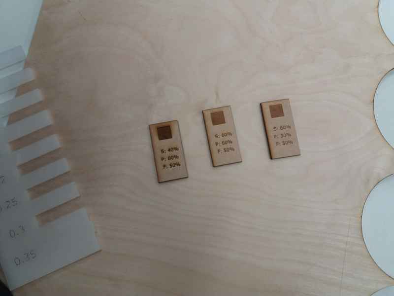
We changed the settings of the laser cutter to see the effect on the material being cut. For cutting we changed the speed and power. We also did the same for engraving where we changed the settings for speed and power. For engraving, we noticed that when the speed is low and the power is high, there were burning traces produced around the engraved area. The best outcome was when the speed was high and the power was reduced as in the image on the right below.
|
Vinyl Cutting
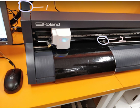
The Vinyl cutter in our Lab is a Roland GS24. I placed a sheet on the machine, pulled the lever (1 in the image below) to hold the sheet in place and positioned the rollers which should be aligned on the grit marks (2 in the image below) to set the cutting area.
|
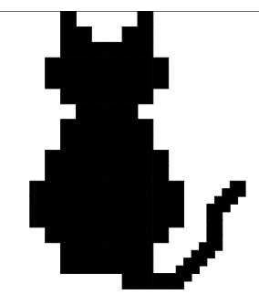
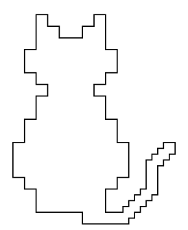
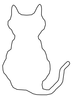
I tried to make a logo of a cat using the vinyl cutter. First I created a pixelated image in Inkscape. I used a 3mmx3mm solid rectangle and just stacked them up like legos to create a cat like image. Then I used the Object to Path command (Shift+Ctrl+C) to convert all the square objects to a path. Then I selected those paths and did multiple Union and combine operation on these paths till I got one combined outline of the pixelated cat. Then I used the edit path by nodes (F2) command and selected individual nodes and moved them around to make the outline a bit smoother. Then I created a rectangular box around my smoothed logo, grouped the whole thing and set the X and Y coordinates of the group to 0 and 0, respectively. After that, resized the page to selection (Shift+Ctrl+R).
|
|
|
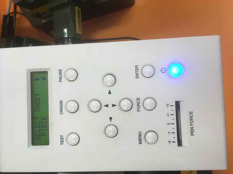
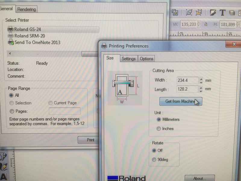
After that, I fired the print in the Roland. I used a cut piece. After loading the piece in the machine, I selected the sheet as “Piece” as shown in the image below and pressed “Enter”. In the Print Preferences of the Roland GS-24, I clicked the “Get from Machine”. This gets the cutting area from the machine. Once this was done, I fired the print. As the page was resized to the desired work piece, no other setting was required.
|
|
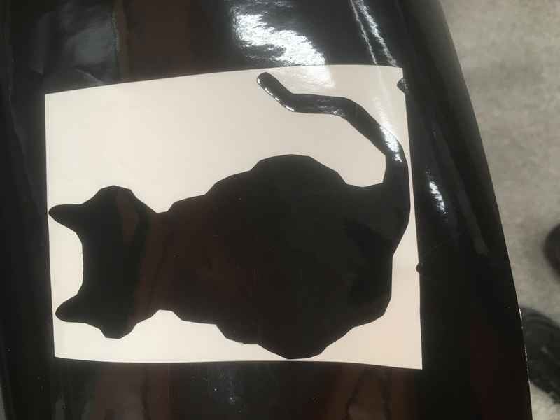
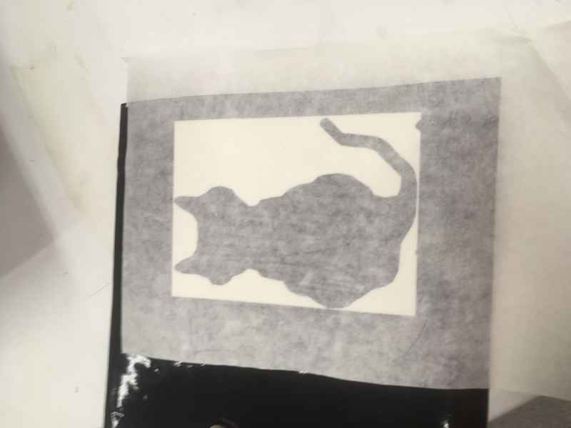
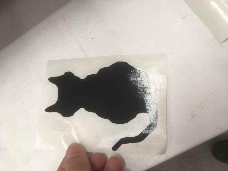
After this, i removed the extra material, stuck the whole thing on the sticky paper, cut that out and I got a sticker. As the image was very simple so no extra tool was required for weeding.
|
|
|
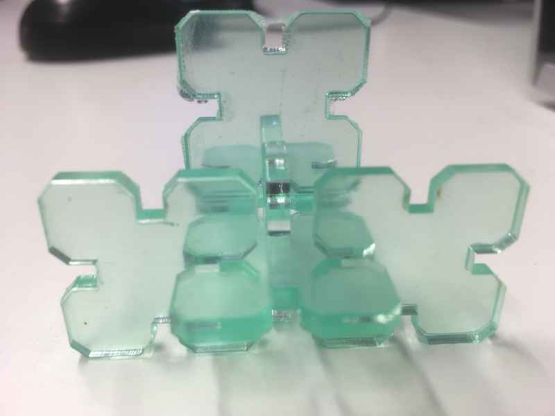
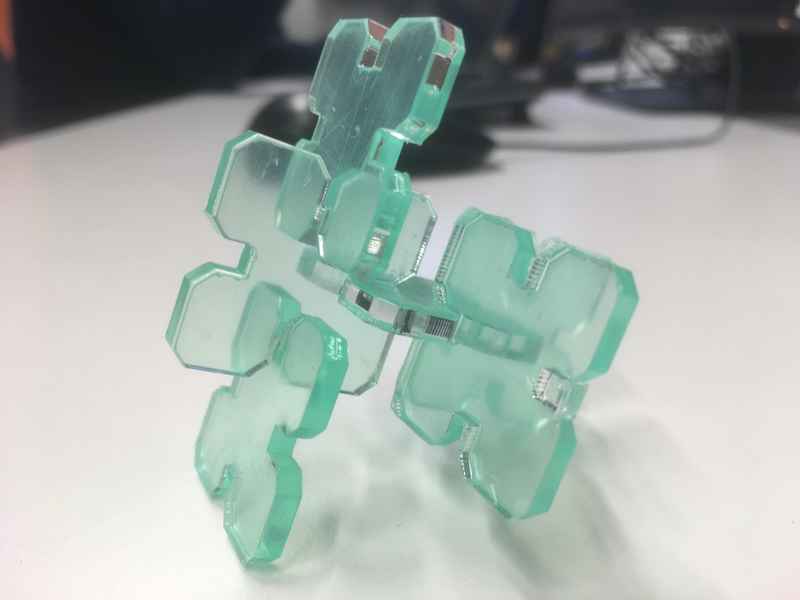
Press Fit design
I don’t really have much imagination so I decided to make the simplest possible press fit design. I defined two parameters, thickness and kerf.
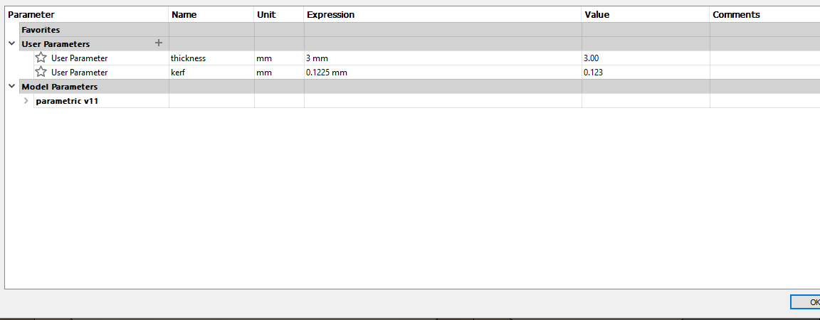
|
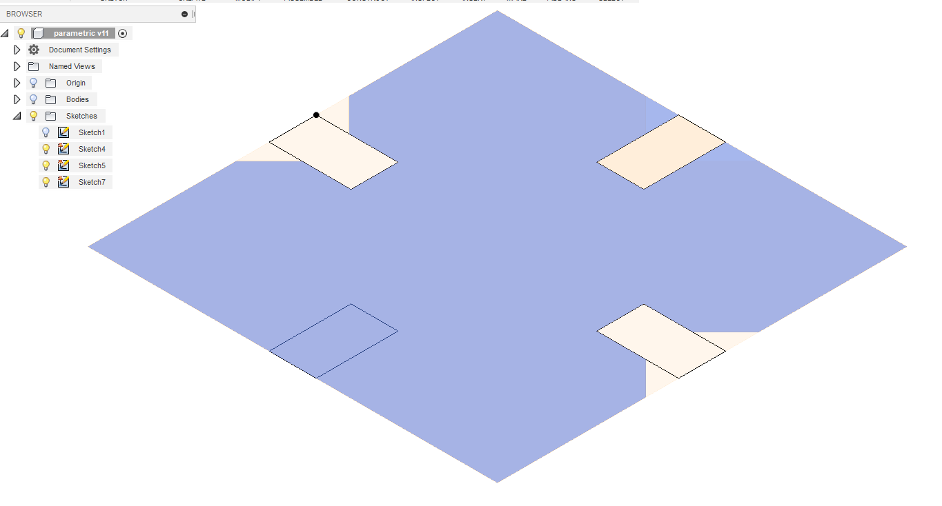
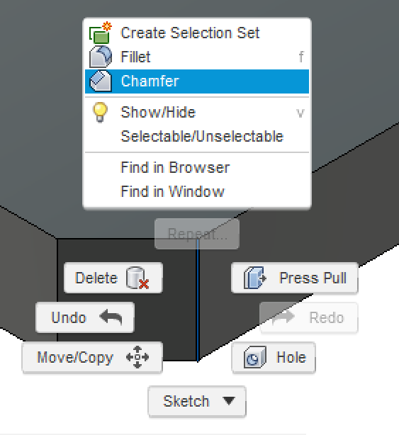
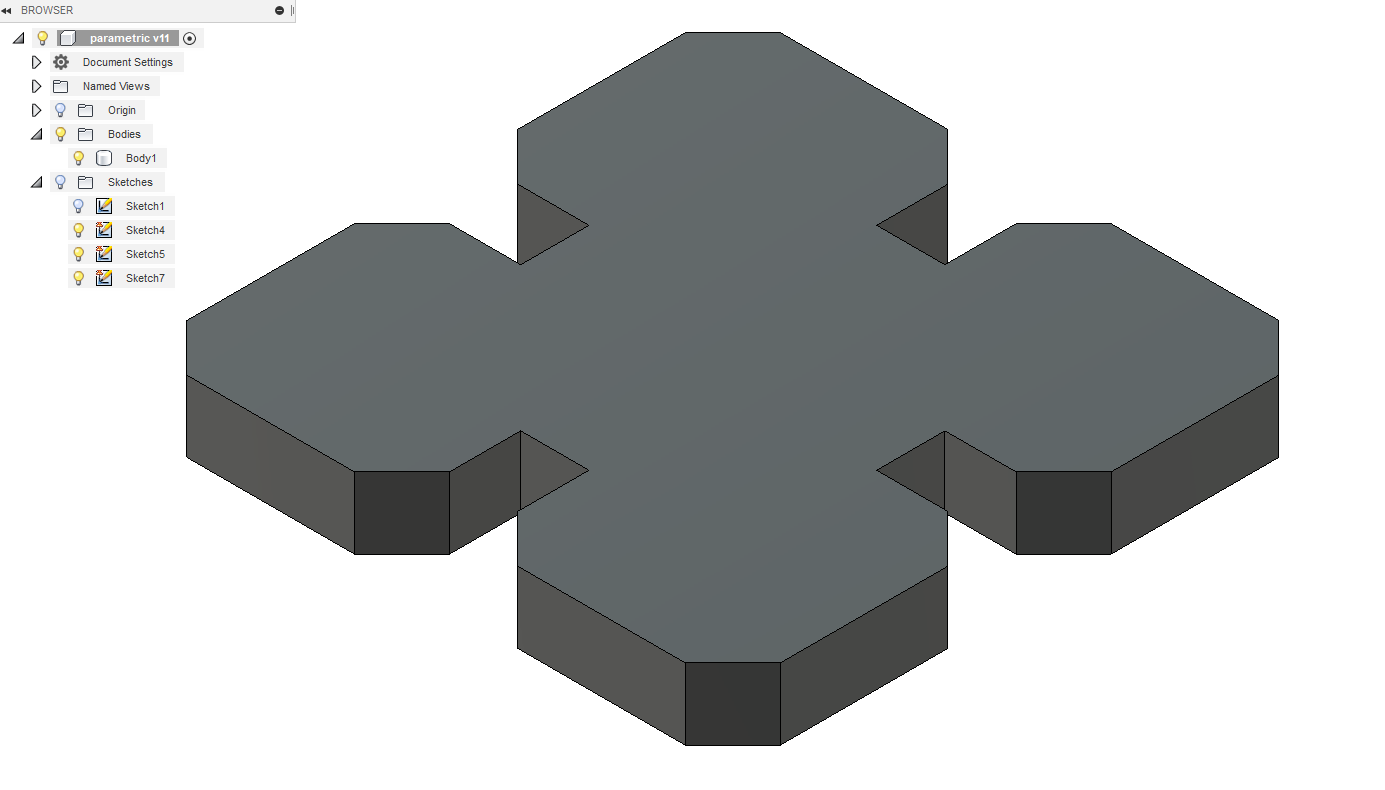
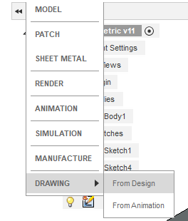
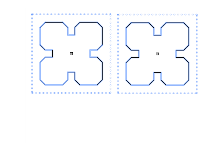
I started with a sketched two point rectangle. Then I created another smaller rectangles which I then subtracted from the original rectangle.I also added two constraints on the smaller rectangle, one was on the size of the rectangle which took into account the kerf and thickness(pressing D for dimension tool and setting the dimension as thickness - kerf). Another constraint was to keep this rectangle in center of the main one, so I used the midpoint constraint. After extruding the sketch I have one body which is parametric. To cut the body via a laser cutter, I need a pdf file with the top view of the body. To get the top view, I made a drawing from the design and placed the top view on the document. The output in pdf format was then taken to Inkscape where the line stroke was changed to 0.02 mm and the document was then sent to print on acrylic.
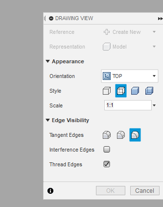
The first attempt was a disaster in a way that every dimension was double than what I actually designed for. As the material thickness didn’t magically doubled, so the first cut didn’t yield a successful run. After some head scratching it was found that while making a drawing out of the parametric design, I accidentally scaled the whole design by 2. Below is a screenshot of the scale dialog box.
|
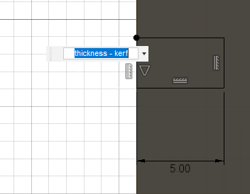
thickness - kerf. |
|
|
|
|
|
|
The finished parametric design can be downloaded from here
Problems
- Inkscape: Problem with clones, can’t merge them or create them to path, so had to just use normal copy in order to merge them.
- Check the scale when making the drawing view from the parametric design, by default it comes as 2:1 instead of 1:1