7. Electronics design
This week I am going to explain you how was my first experience designing electronic circuits.
Group assignment
As a remote student I am alone in the FabLab, so I have to do this part individually. *
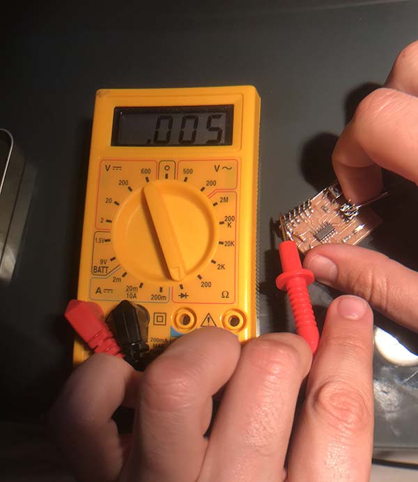
With the multimeter I have been checked the continuity in the PCB. Our instructor Nuria, recommend us to use it all the time. I set a component and I check that there is continuity. That gives me confidence and allows me to check that the component is good soldered.
First we need to select this symbol, that means continuity. 1 means no continuity
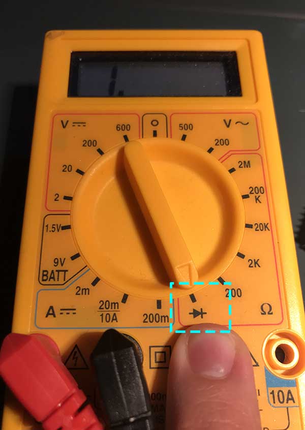
Now its the turn of check the GND continuity, 5V, etc but at least this one because that means it could be fine. 1>0 means continuity
Discovering Eagle PCB Design
In this remote team that we are studying together, almost everyone did not have any experience with electronics. For that reason our tutors gave us a little tutorial to start using Eagle this week to design PCB.
First you need to download and instal the software:
As students you have 3 years for free
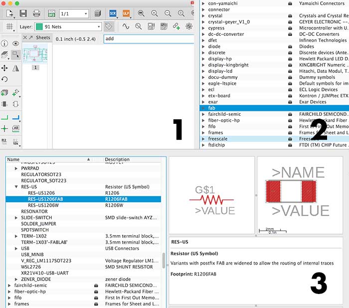
Then, following the tutorial as every week, you need to instal libraries of components to star designing, I have found some silly problems:
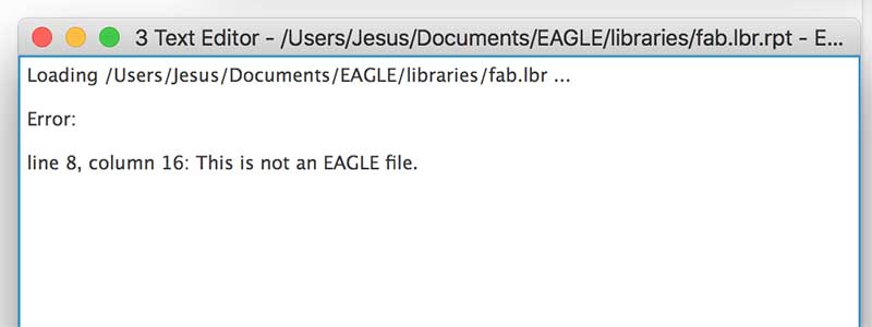
At the end, I achieved resolve the problem because I was downloading the files wrong:
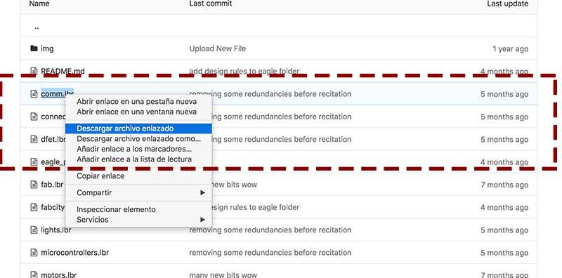
I was downloading each file individually by typing over it, and it does not work in the program
You only have to download a .zip file and decompress… It will work normally.
Just copy all .lbr files and copy in the directory …/Documents/Eagle/library/
Then you will find in the toolbar Libray > open library manager and there you will find all of these components.
Create a New Project, and create now a New Schematic layout.
There are some useful commands I attach below:
- add - to add components
- move - to move each piece
- rotate - to rotate every part 360º
- net - to connect the components
- Delete - to erase any draw
When you have all the components added as the tutorial picture:
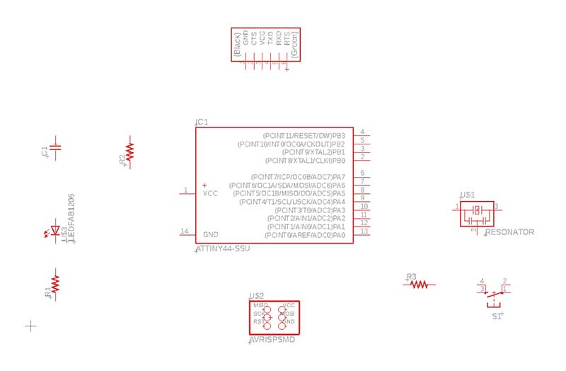
Now you have to link all the components with the net command
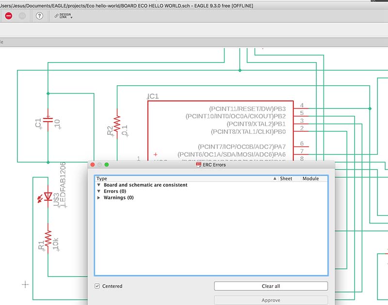
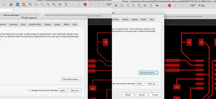
When you finish you have to check errors with ERC tool and you will need a command bar like this
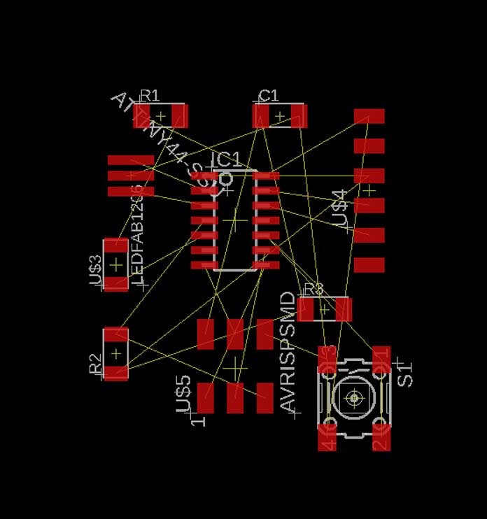
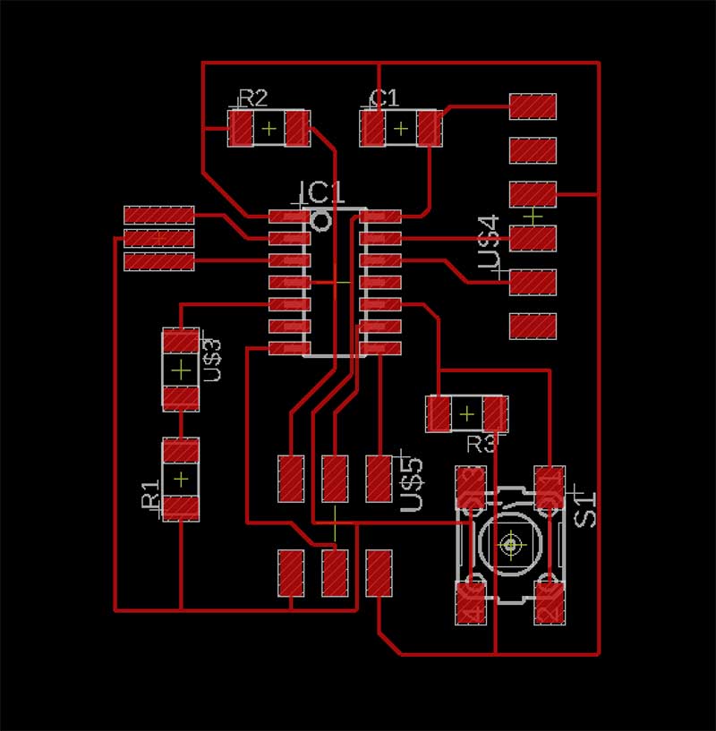
After you do this, change Schematic layout to Board in the upper toolbar. At the beginning you will have something disorganized like this:
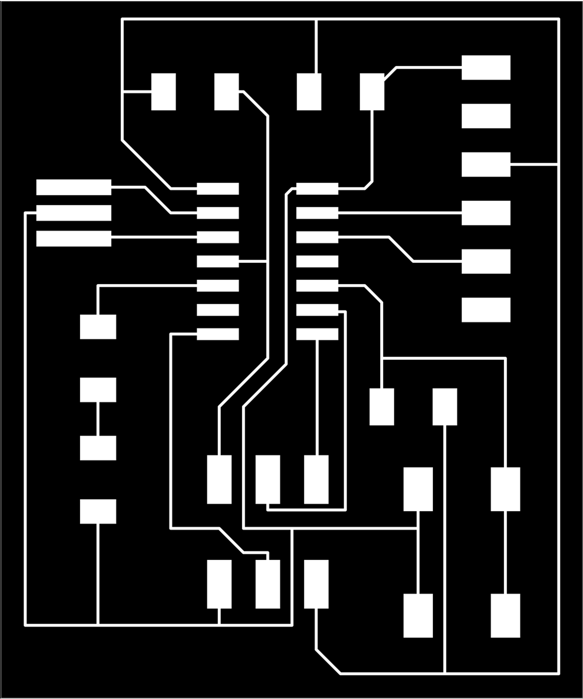
You just have to reorganize the components, rotate and move and connect them to achieve something like this:
(There are 2 forms AutoRoute and Manual. I did this manually I don´t like autoroute)
The steps to Add any component is This
!!Its important to know that you need to put a resistor before Leds because you need to reduce the electric current flow.
Exporting PCB
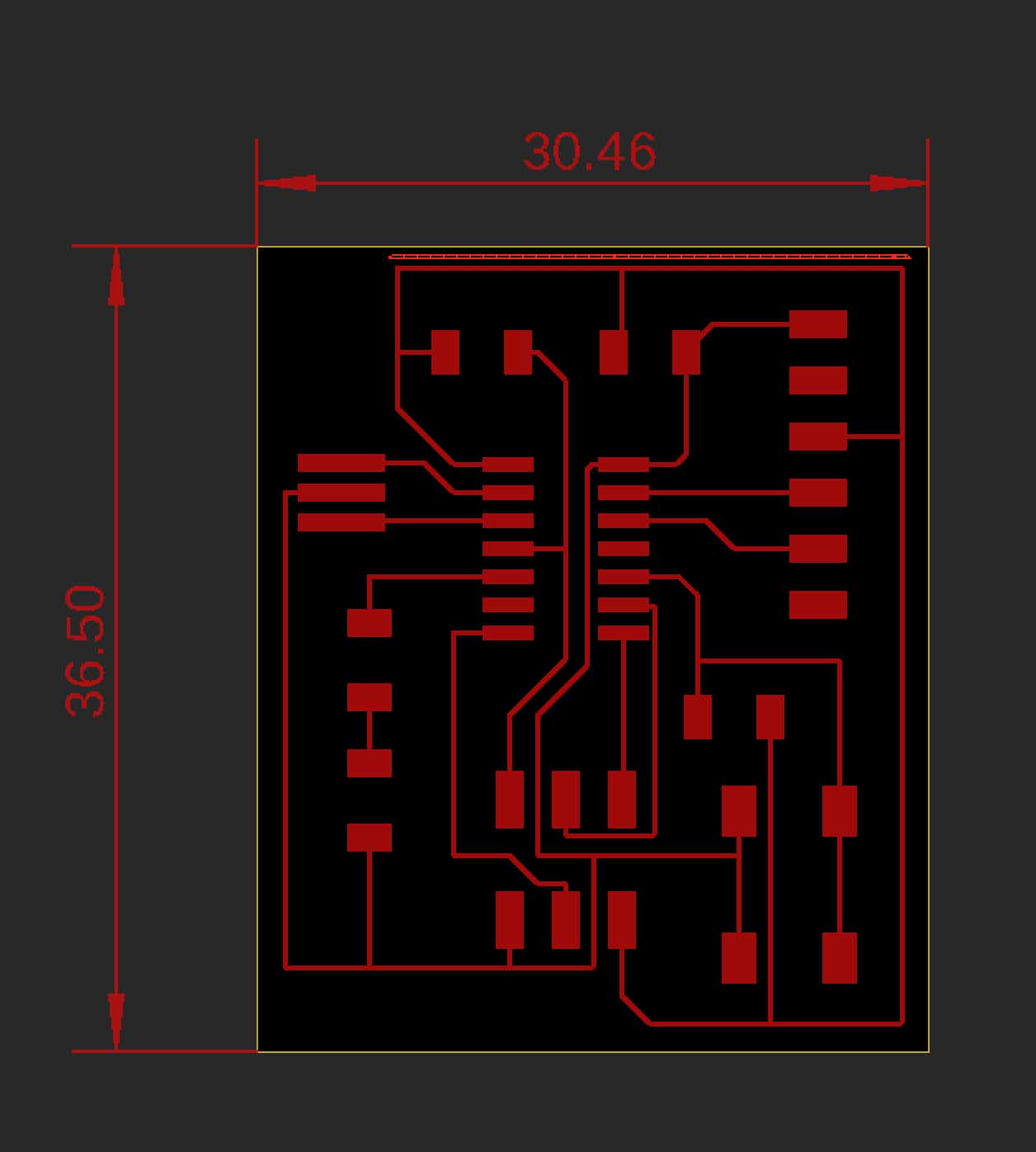
First you will need the real dimension to know them and test there are correct when you open in other programs:
Now go to Export > image > PNG
- Monocrome √
- Resolution 1000 DPI
- Area full
you can modify Board layout just dragging the limits of it.
- I forgot to check DRC, and my traces are so slim, I have corrected downloading from here in FabAcademy web and > tools > DRC > Load > Apply.
You have to redraw the traces again, but you won’t have errors!
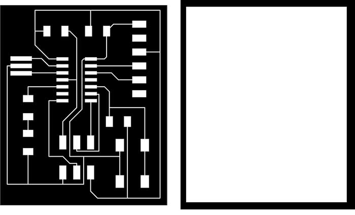
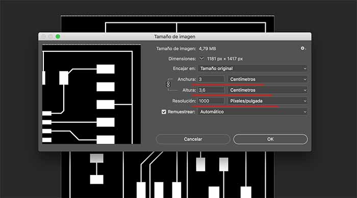
Photoshop .PNG adjusting size
In any bitmap program, I have used Photoshop crop and generate outline .png image:
Here you can check the measures and the resolution for FabModules
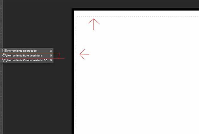
And here you just generate a rectangle with the selector and with this tool fill inside of white.
Generating PCB
As we did in the last assignment 5 week performing the milling machine, placing the base and fixed it, and calibrate Z axis and Origin.
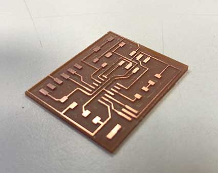
I have used the same configuration, the same mills and the same FR1 copper boards.
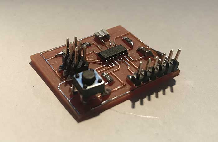
Soldering Components
For this practice you will need the following components:
1x ATtiny44
1x 499Ω resistors
2x 10kΩ resistors
1x 1uF capacitor
1x 20MHz resonator
1x 2x3 pin header (ISP)
6x Male headers
1x Smd Switch
1x FTDI Wire
The truth is that I have found soldering so relaxing and I like it a lot!
Here is the result of the board and you will have your HelloBoard finished.
We will continue programing and testing the next week. Thanks for reading.

Este obra está bajo una licencia de Creative Commons Reconocimiento-NoComercial-CompartirIgual 4.0 Internacional.