
Assignments
- Document your individual contribution.
Subject
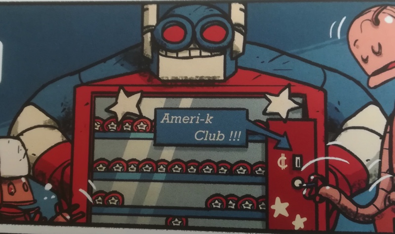
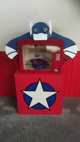
Each year, Amiens, our city, hosts a famous comics festival. This year we have the opportunity to participate to the construction of an exhibit on a comic from Steve Baker named Bots. For this event we decided to construct a badge automatic disposer inspired by this:
My contribution
As part of this project, I took care of: - the design and manufacture of the robot’s head - the design and manufacture of the frame receiving the delta robot - automation of the eyes of the robot’s head
Design process
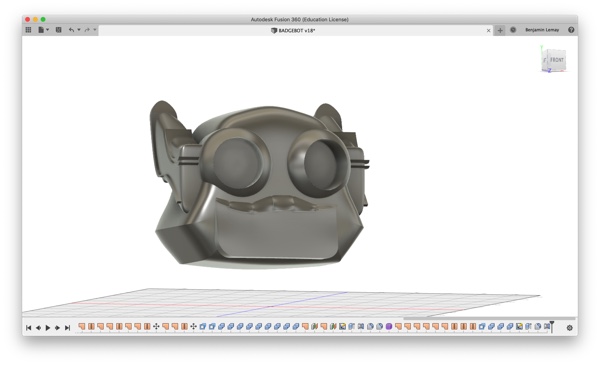
I used the module form, patch and model of Fusion 360 to model the head and the frame. I used a canvas image to guide me in the design process.
Model the head: main steps
| 1. Insert image as canvas | 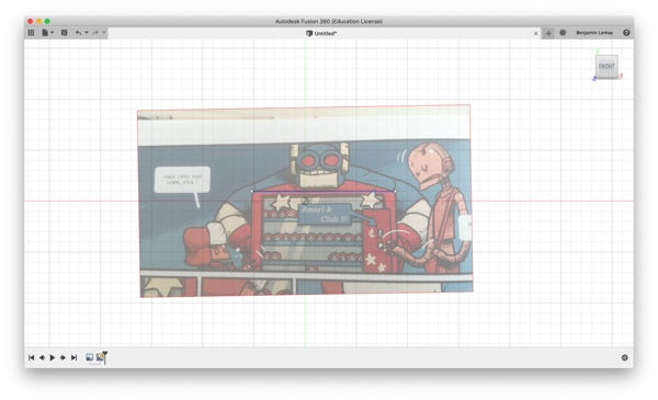 |
|---|---|
| 2. Set the position, size and orientation | 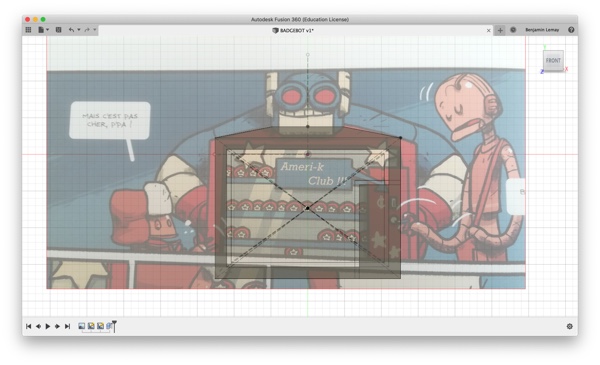 |
| 3. Set parameters | 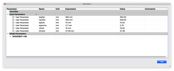 |
| 4. Design the front panel | 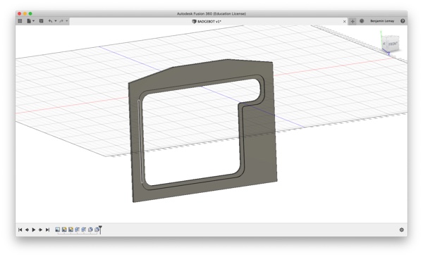 |
| 5. Use create form menu |  |
| 6. Create box and set a length symmetry | 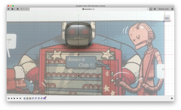 |
| 7. Edit form and move edges with the canvas as guide | 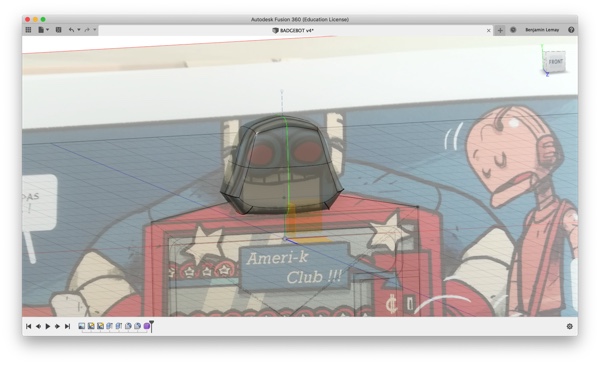 |
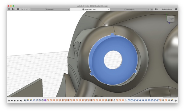
| 8. Create concentric cylinder for the eyes | 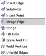 |
| 9.Merge edges and use mirror to duplicate the eye | 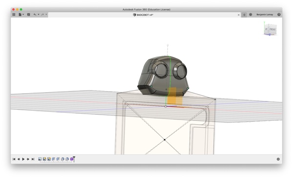 |
| 10.Create sketch for the tooth and jaw | 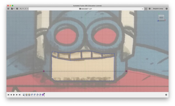 |
| 11.Extrude from the sketch | 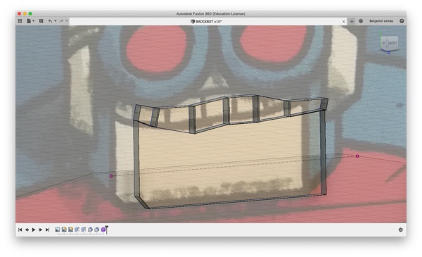 |
| 12.Modify shape of tooth and jaw with edit form | 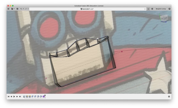 |
| 13.Finish form | 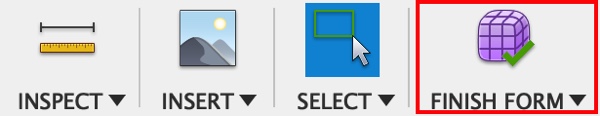 |
| 14.Use patch menu to close the tooth and jaw | 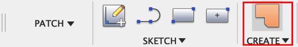 |
| 15.Use patch and stitch to make body from surfaces | 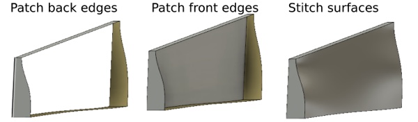 |
| 16.Use model menu to combine bodies | 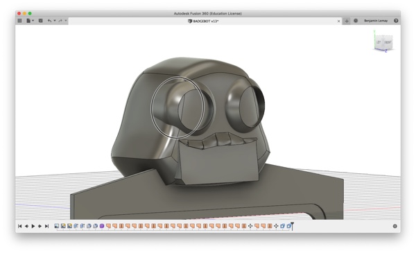 |
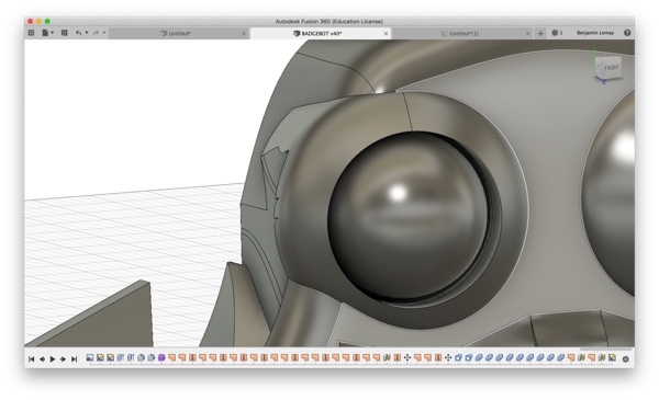
It is with the same tools that I modeled the ears, to obtain this final result:
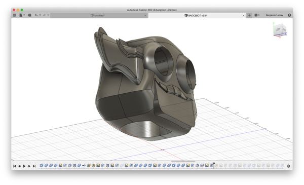
Anticipation of the production process
In order to wire the LEDs and engines of the eyes I created a hollow at the base of the head. This will also reduce the PLA used for 3D printing.
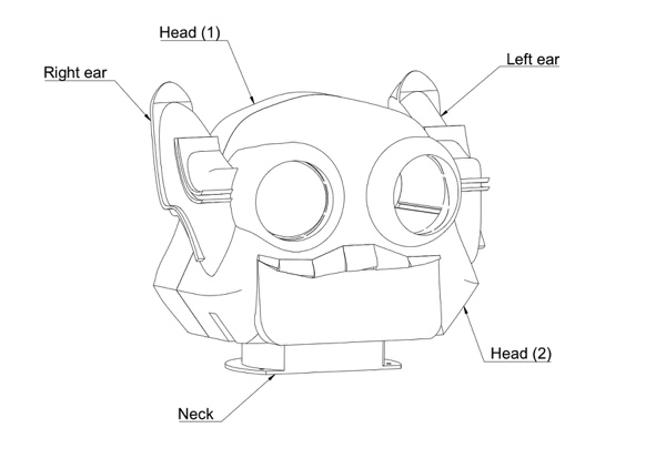
In order to facilitate 3D printing the model has been broken down into 5 distinct parts:
- Head 1:STL
- Head 2:STL
- Left ear:STL
- Right ear:STL
- Neck (to fasten the head to the top panel):STL
- Eyes:STL
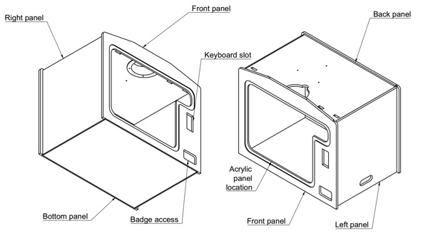
Design of the frame
The structure has been designed to be milled in 10mm plywood. The assembly is done by interlocking. On the front a transparent acrylic panel will be installed. The front panel has a badges access hole and a keyboard slot. The left panel is removable to allow access to the electronics and the tank of badges.
Eyes design
On the head of the robot we planned to illuminate and rotate when the delta robot catch a badge. For this I created engine mounts that will be cut in an acrylic panel. The eyes are half-spheres that will be 3D printed.
| Engine mount | Eye |
|---|---|
 |
 |
Manufacturing process
3D printing
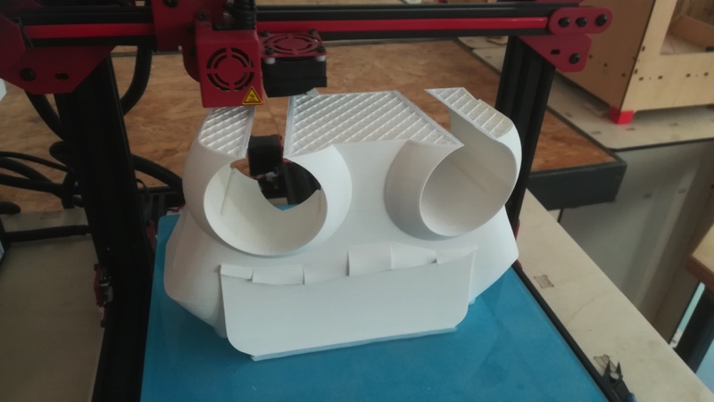
FDM 3D printing
To print the head’s parts except the eyes I used the Alfawise U20 (french). I tried Cura 4 and I used the following parameters: - Layer height: 0,12 mm - Wall thickness: 0,4 mm - Top/bottom thickness: 0,8 mm - Infill density: 10% - Printing temperature: 235°C - Build plate temperature: 60°C - Print speed: 40 mm/s - Build plate adhesion type: Brim
The head 1 and head 2 parts took each one 50 hours to be printed !
SLA 3D printing
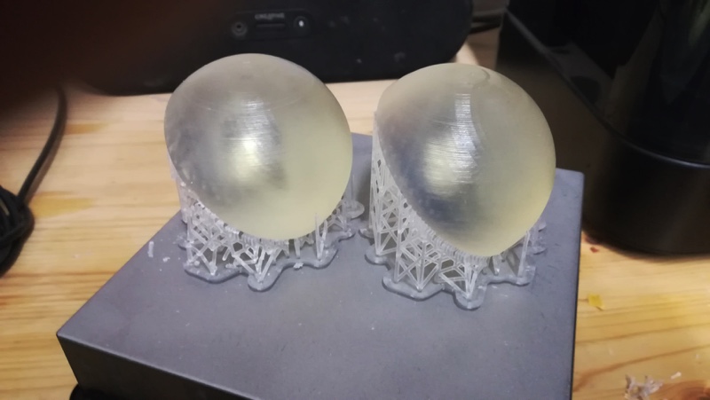
As I wanted to have a transparent material for the eyes, I did not have much choice. I first thought of creating a mold and casting a transparent resin but I gave it up because it would have been too long. There was still a transparent resin cartridge open in our Form 2, so I used this machine.
Preform
| Set parameters | 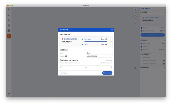 |
|---|---|
| Open the file | 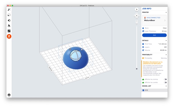 |
| Use one click print tool | 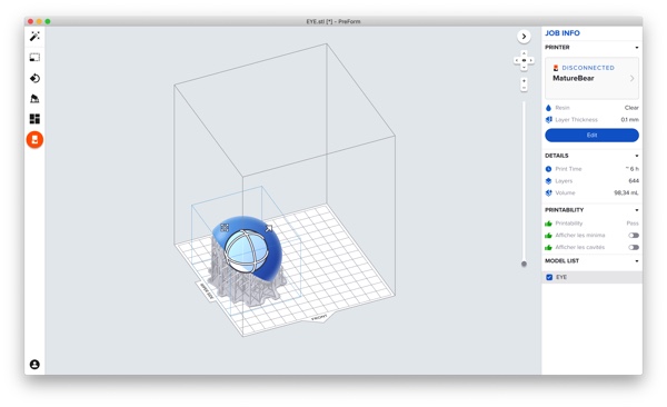 |
| Use layout to duplicate | 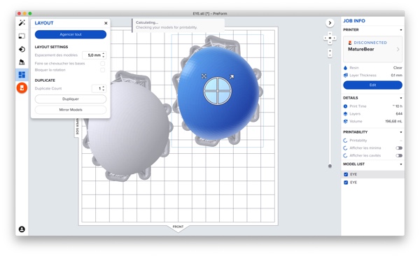 |
| Connect the printer and print | 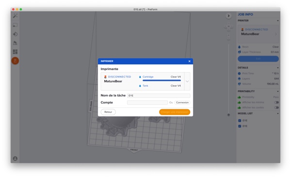 |
Problem to print with the Form 2
After launching the print, the Form 2 displayed an error message: “Resin sensor reported an error. Check for sensor contamination or try reseating the tank.“
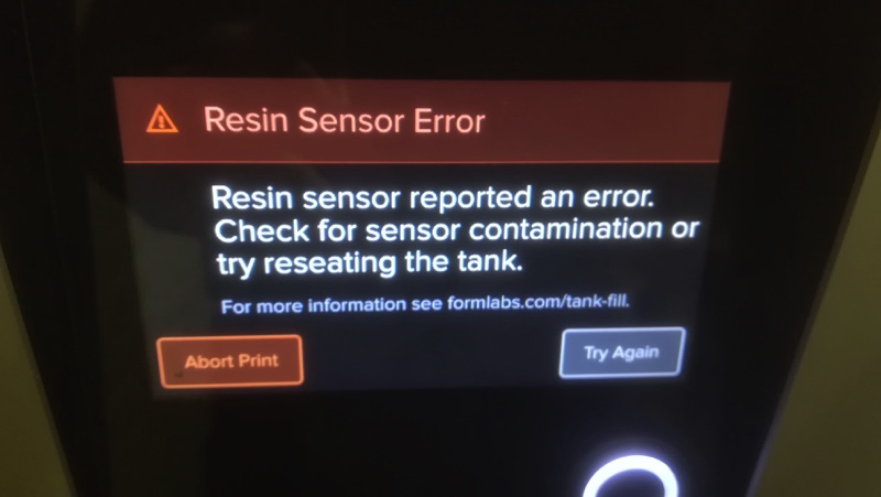
I checked this page to know how to fix this issue. I removed the resin tank and cleaned the resin tank sensor but the error message was still here… After that, I removed and re-inserted the cartridge and the error message disappeared.
The result
Post-processing
- Use Form wash to clean the parts and remove the resin non-polymerized
- Cut the supports
- Use Form cure to increase the mechanical properties
- Sand and polish the surface (with 240/500/800/1000/3000/4000 grit sandpaper)
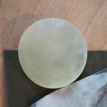
Result after sanding with 500 grit sandpaper
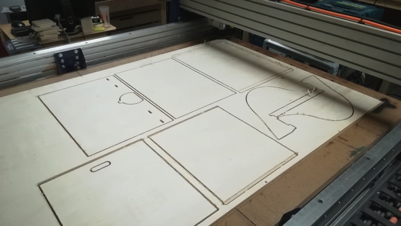
CNC machining
The machining of the panels was done with the Shopbot PRSalpha 96-48-8. I used poplar plywood 10mm in thickness. I machined the front panel separately because it ‘s a double face machining. The machining files have been generated with Vcarve. (To know how to use it you can refer to this video )
Problem with the machining parameters
For this job used a new end mill that I have never tried before. I used the same setting that I used with the 1/4” Downcut end mill because I thought they have about the same characteristics. However the quality of the cut was not good (fibers pullout).
Finally, I contacted the vendor and he gave me a very good and professional advises. I retried to use this new end mill with this parameters and the result was really good:
- Feedrate: vf = 3500mm/mini
- Spindle speed: n = 18000 RPM
- Cutting depth: 6mm
To find this parameters I used this formulas:
- n = (1000 x vc)/(Pi x d)
- vf = n x fz x Z
with:
- n: spindle speed (tr/min)
- d: tool diameter (mm)
- z: tooth number
- vc: cutspeed (m/min)
- fz: feed per teeth (mm/teeth)
- vf: feedrate (mm/min)
I highly recommend CNC fraises for the quality of its products and service.
Assembly
Frame assembly
I used wood glue to assemble the different panels.
| The parts | 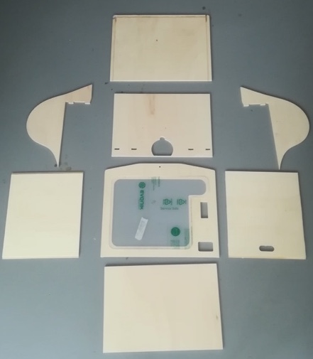 |
|---|---|
| Top and back panels | 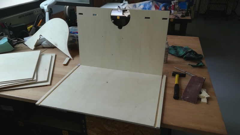 |
| Right panel | 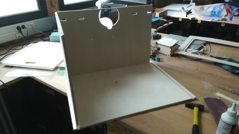 |
| Front panel | 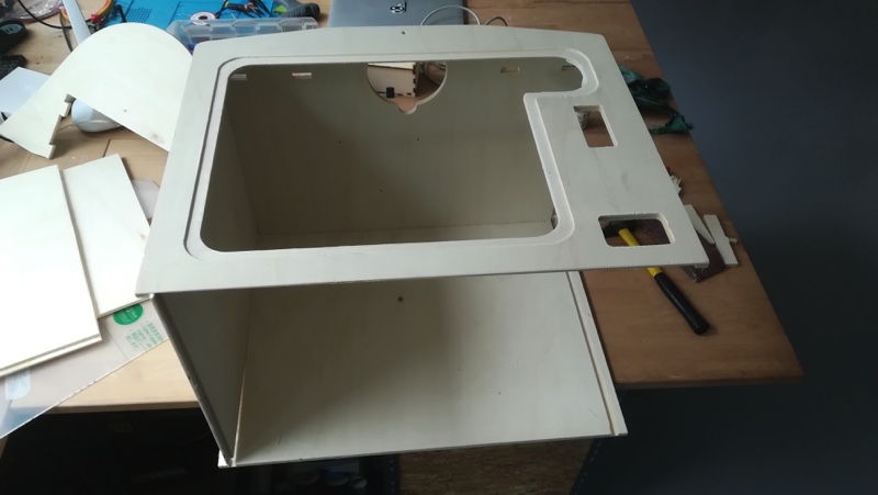 |
| Bottom panel | 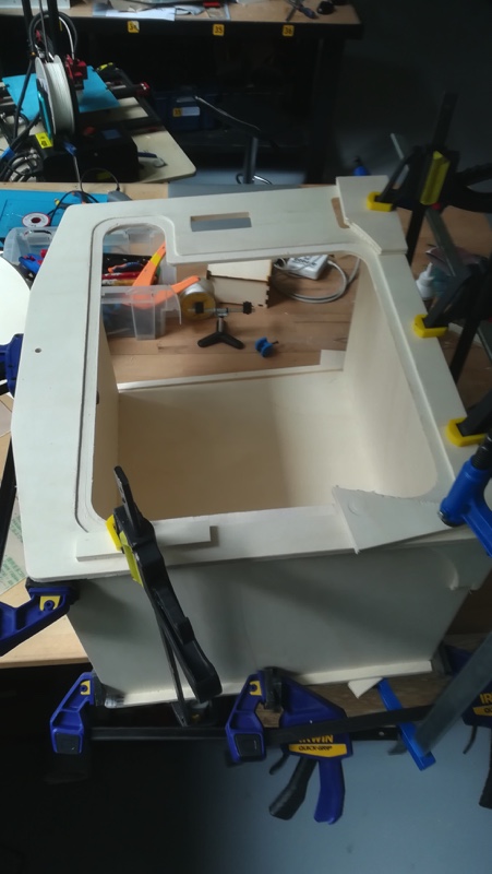 |
| After painting | 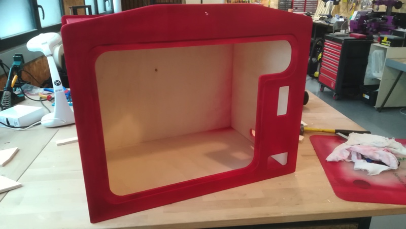 |
| Fasten the neck | 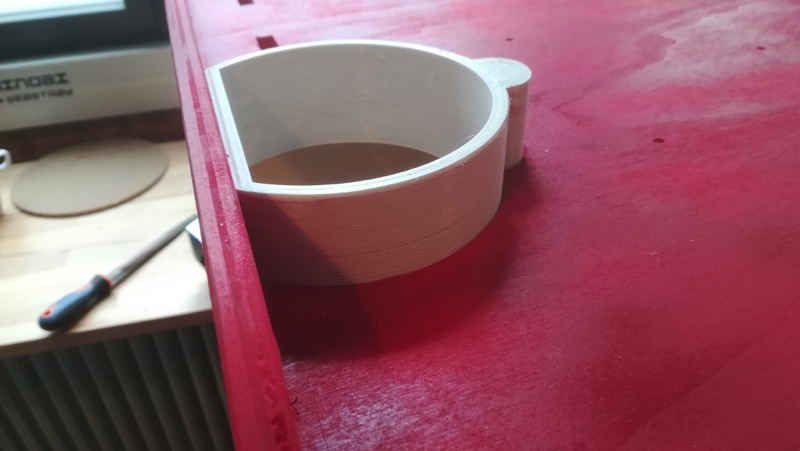 |
| Fasten the delta bot | 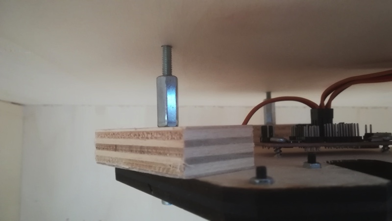 |
| Frame with the delta bot | 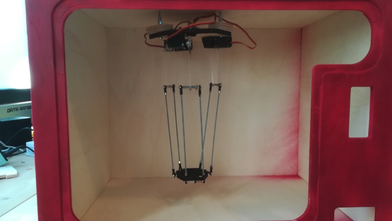 |
| Delivery ramp | 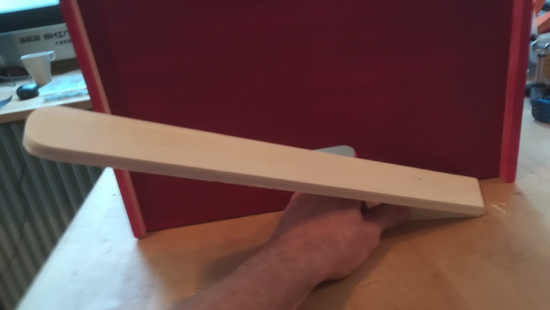 |
Head assembly
| Engine mounting | 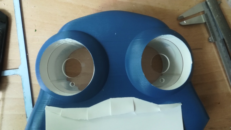 |
|---|---|
| LED and resistor soldering | 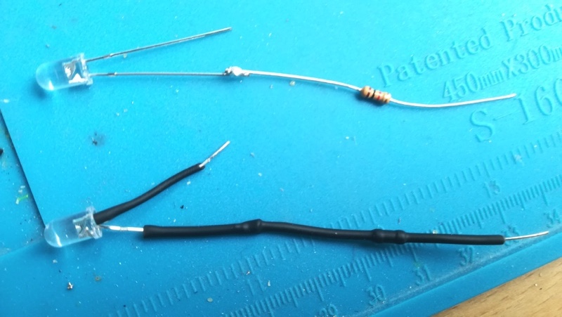 |
| Electrical connection | 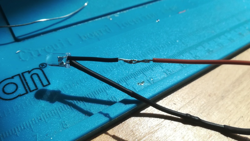 |
| Wire soldering | 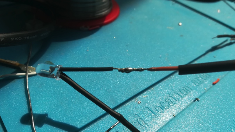 |
| Motor connection | 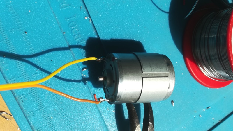 |
| LED fastening (glued) | 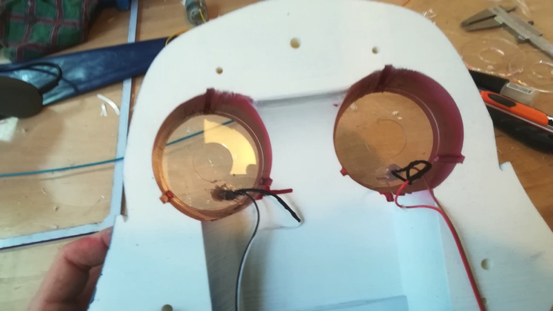 |
| Motor fastening (glued) | 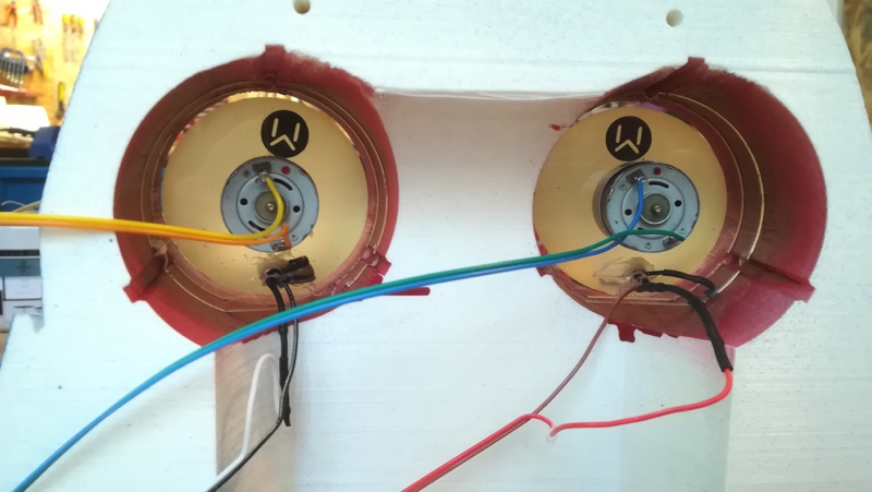 |
| Pulley fastening (glued) | 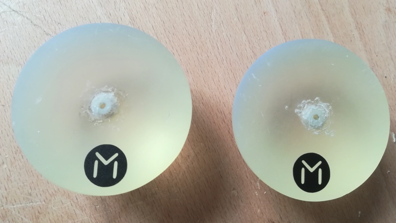 |
| Pulley fastening (glued) | 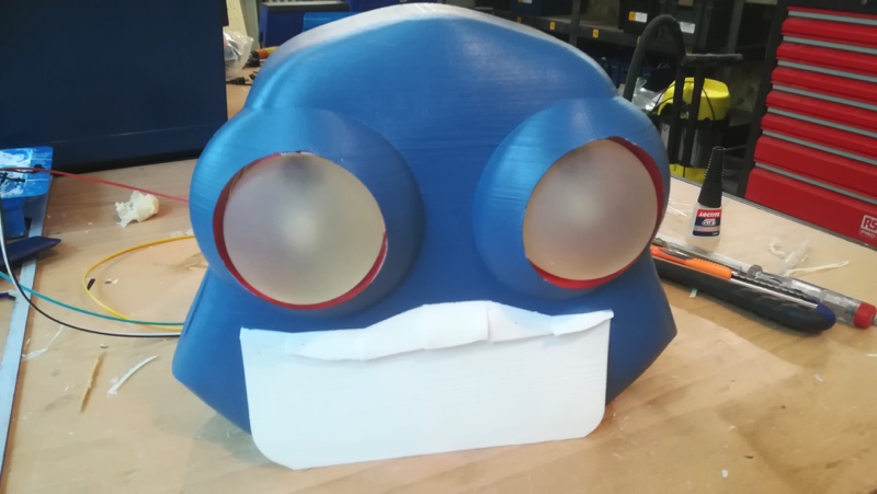 |
Final result
Downloads
- Panels, windows and engine mountings PDF , DXF
- Head 1:STL
- Head 2:STL
- Left ear:STL
- Right ear:STL
- Neck (to fasten the head to the top panel):STL
- Eyes:STL