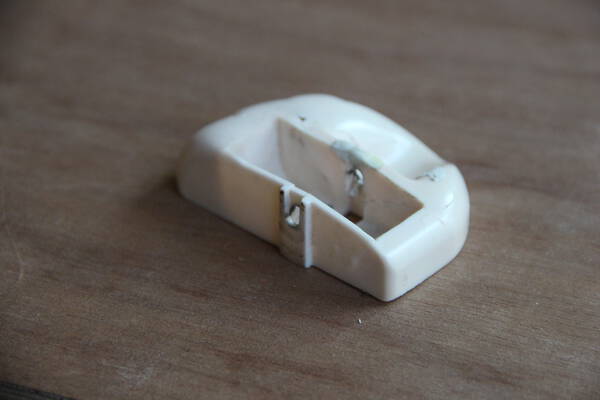
For this week I wanted to experiment with using the DAVID structured light 3D scanner. The subject: the reproduction of a broken toy piece.
Assignments
- Design and 3D print an object that could not be made subtractively
- 3D scan an object
- 3D Print it
Subject
I chose to work on the reproduction of a broken toy piece. The idea is to roughly repair the piece to be able to scan it, rework it in a modeling software and 3D print it.
Scanning Process
Repairing and gluing the part
| TOY PIECE | ||
|---|---|---|
| Repairing the damaged part with modeling clay | 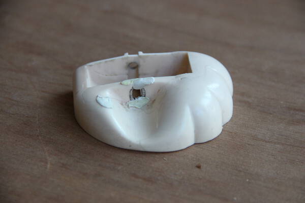 |
 |
List of equipment
- PC
- David LED projector
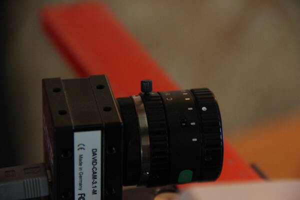
- David HD Camera
- Tripod
- Calibration panel
- Turntable
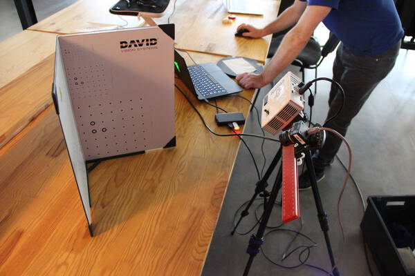
First checks
- It’s important to do the work in a room that does not receive stray light
- In the “installation matériel” (i don’t know the name of this tab in the english version) make sure that camera and LED projector are recognized
- Choose the right screen for the LED projector
Setting the equipments
-
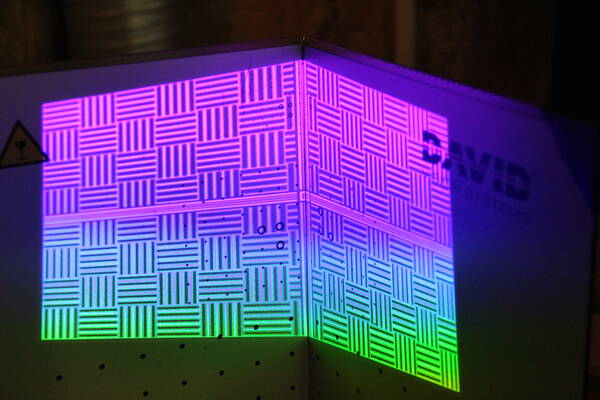
Choosing the size of the target: Depending on the size of the object to be scanned, it is necessary to choose the size of the target that will be used. Several choices are possible on the calibration panel. Here we choose 60mm (maximal dimension of the object).
-
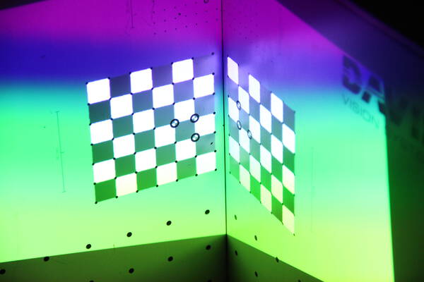
Positioning of the equipment: It is necessary to match the center of the projection (marked by a square) with the center of the chosen target of the calibration panel.
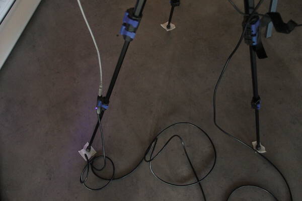
Trick: It is possible to locate the position of the calibration panel and the tripod with tape to don’t lose the equipments position:
-
Setting the LED projector focus: It is necessary to adjust the sharpness of the projected image using the LED projector wheel
-
Setting the camera focus: to have a clear image, for that, adjust the focus ring.
-
Positioning of the camera: Adjusting the camera’s orientation so that the center of the image matches the center of the projection
-
Setting the opening of the camera diaphragm: Adjusting the opening of the camera diaphragm to get a contrasting picture. The idea is to get a good contrast to get the red lines in the blue lines.
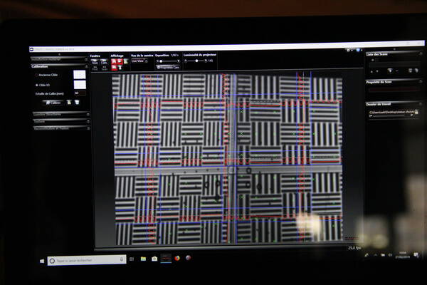
Calibration
In the calibration tab, choose the calibration panel (here V3) and click on the calibration button. If the job was good you get the triangulation angles between the LED projector and the camera.
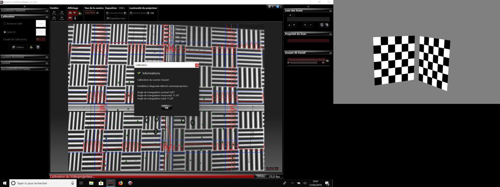
We can observe the correspondence between the projected image and the target of the calibration panel
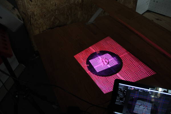
Positioning the object
When the calibration is done, it is possible to remove the calibration panel to install the object. It must be positioned in the center of the image. For this it’s possible to play on the orientation and the position of the rail supporting the camera and the LED projector.
Trick: To facilitate the alignment of different shots, we used a sheet of paper under the object. The corners of the sheet will serve as a reference.
Shooting
In the structured light tab you have to choose the quality of the shots (here by default) and the orientation (vertical or horizontal) of the pattern (if the object to be scanned does not have a particular symmetry it is necessary to choose both).
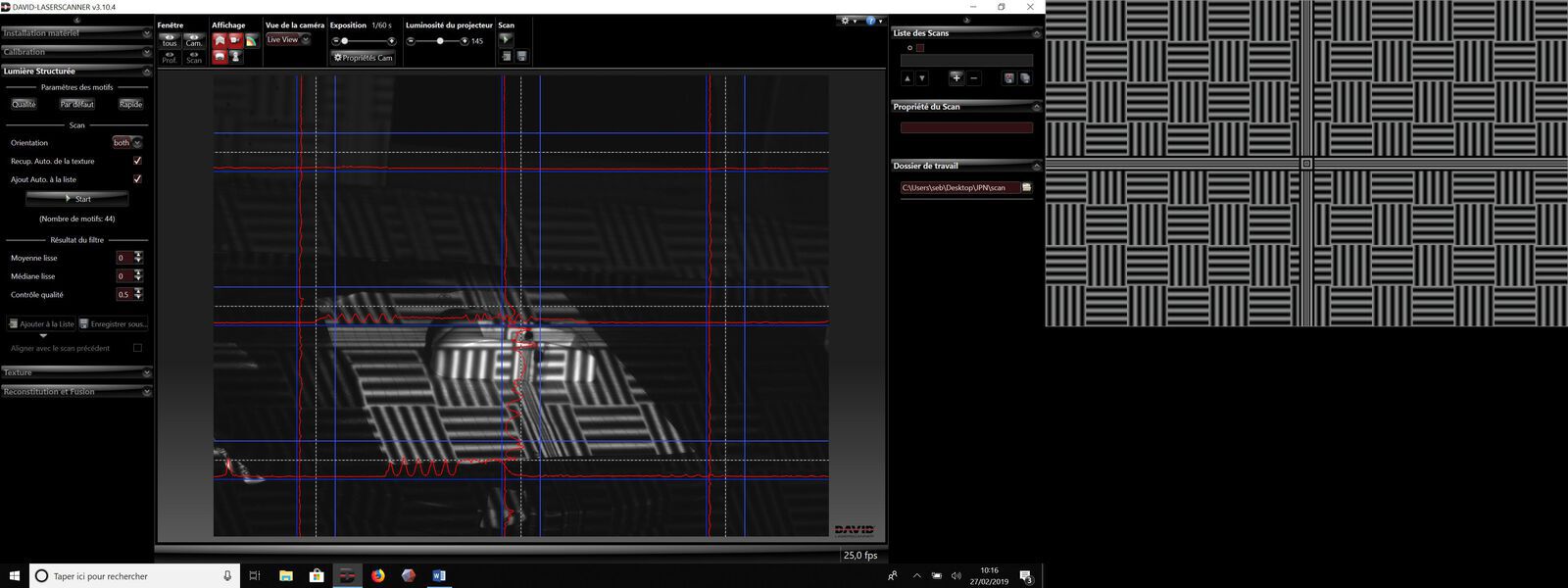
Before starting it’s necessary to define the saving folder of the .obj files.
Now, we can click start to make the first shoot. The first scan appears in the scans list on the right side.
It’s necessary to change the position of the object with the turntable to make all the necessary shots.
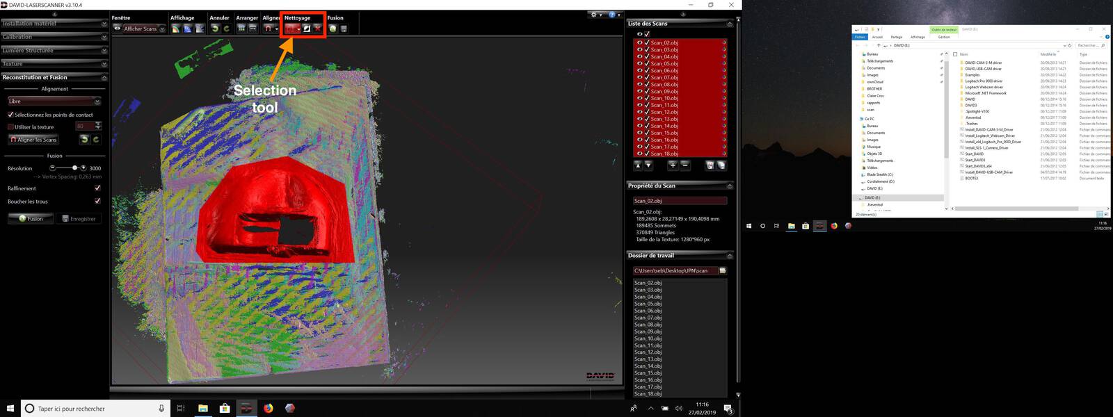
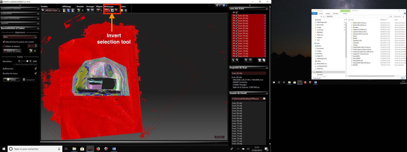
Cleaning
Before the scan alignment step, it is best to clean up the scans. This will facilitate the calculations of alignments.
-
Objects selection:
-
Invert the selection:
-
Remove the useless parts:

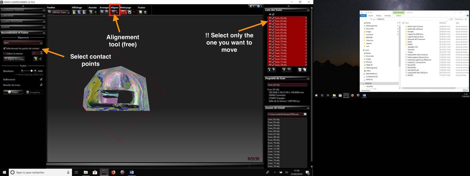
Alignment
Free alignment
Once all the shots have been taken, a first stage of a free alignment of the scans is required. For this it is necessary to select in the scans list which one we want to align (check the box of the one which you want to move). Use the free alignment tool and select contact points.
Click first on the point of the scan to move and then on the corresponding point of the reference scan.
(Tip: holding down the control key to move only the selected scan)
Move all the scans in the same way compared to the reference scan (the first one for us).
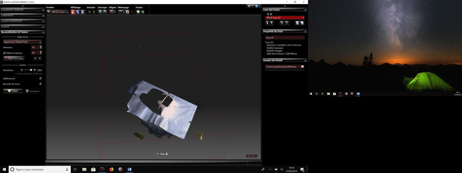
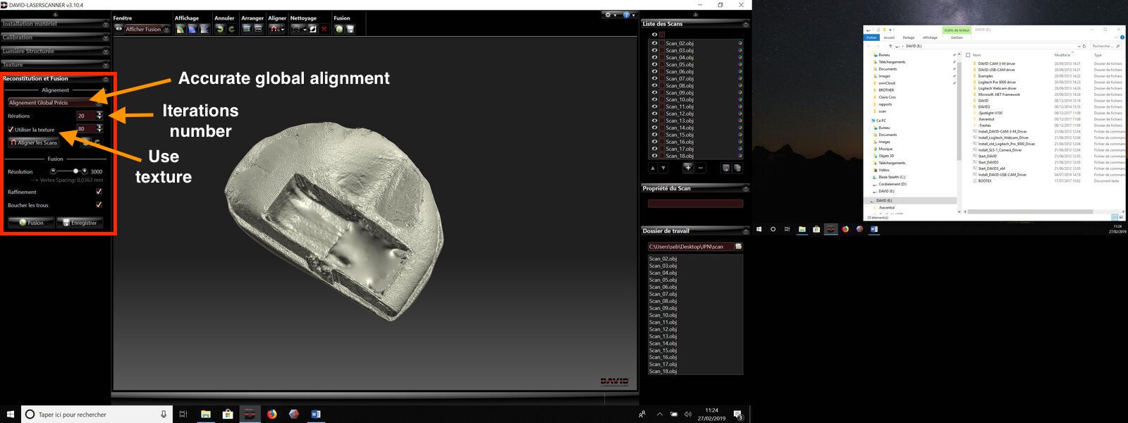
Accurate global alignment
Once the free alignment of each scan is done, it is necessary to use the accurate global alignment.
Select “use texture” to facilitate alignment. It is possible to choose the number of iterations (here 20).
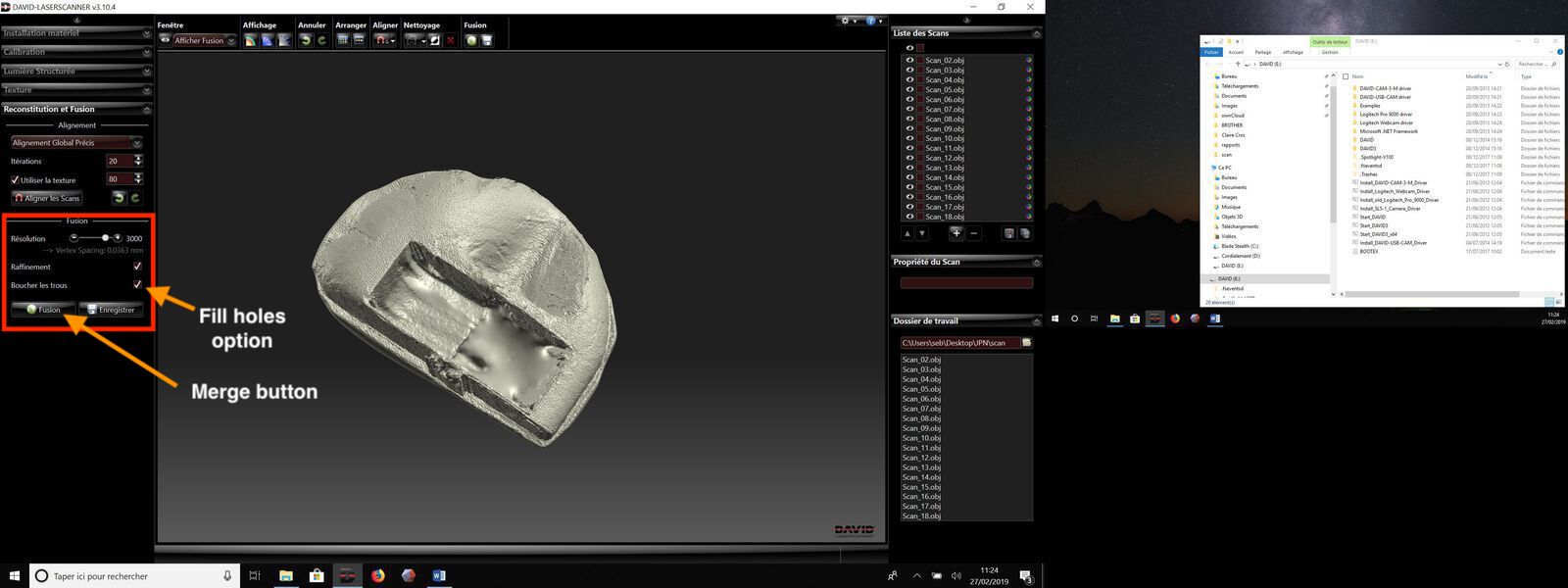
Fusion
Once alignment is complete, it is possible to merge the objects and to save the 3D file (.obj).
Final result:

Note: Having selected fill hole option, after the merge an excrescence is created under the object. This can be removed when correcting defects with Meshmixer.
Modeling Process with Meshmixer
| Editing the mesh | ||
|---|---|---|
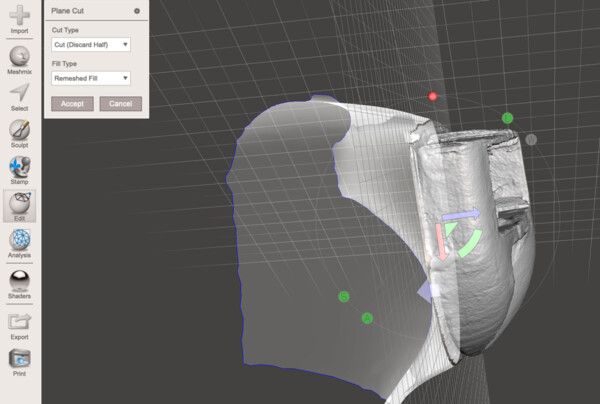
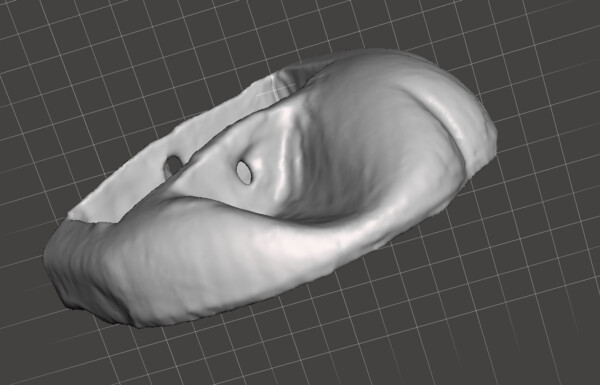
| Cutting the excrescence: select plane cut in the Edit menu then position the plan to match the location of the cut) | 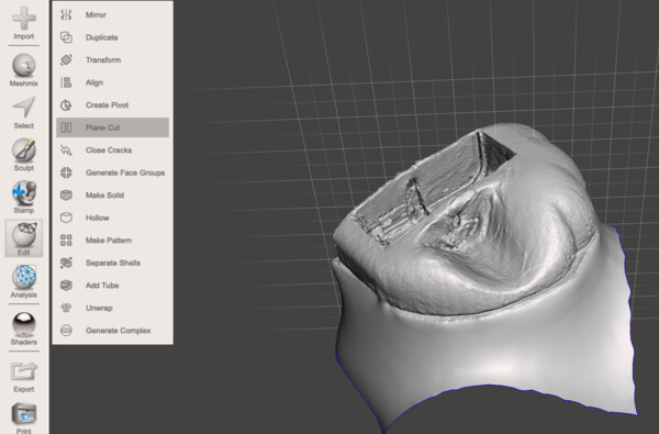 |
 |
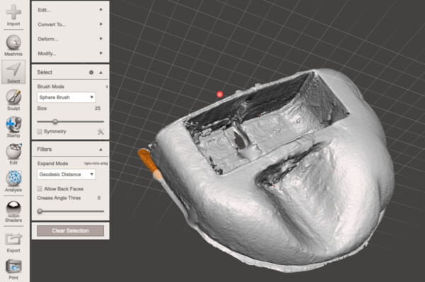
| In the select menu choose the brush set it the size and select the parts to remove (orange coloration). Then remove them with the delete key. | 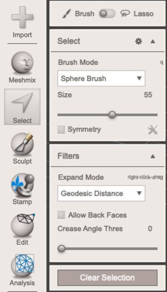 |
 |
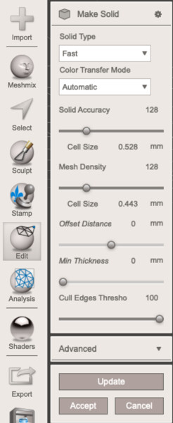
| In the edit menu select make solid to automatically fill holes and create solid (it’s possible to choose the solid accuracy and the mesh density) | 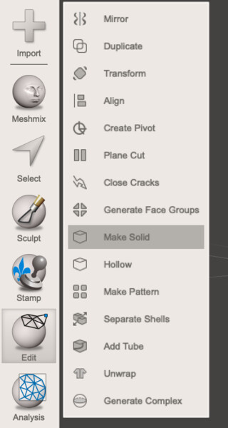 |
 |
| To even the surface of the solid use the flatten brush in the sculpt menu. | 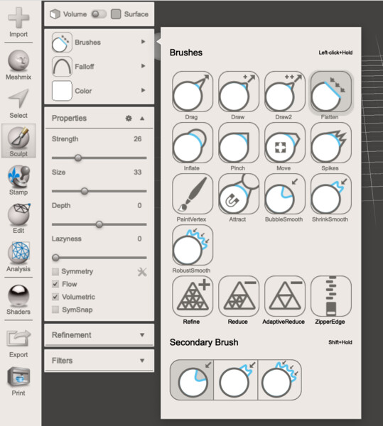 |
 |
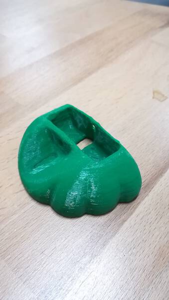
3D printing with Ultimaker original
I did a first test print with our faithful Ultimaker original. I used the Cura slicer to generate the gcode using the following parameters:
- Nozzle diameter: 0,4mm
- Nozzle temperature: 230°C
- Bed temperature: 70°C
- Layer height: 0,15mm
- Wall width: O,8mm
- Top and bottom thickness: 1,5mm
- Infill density: 10%
- Print speed 40mm/s
- Build blade adhesion type: brim (5 lines)
- Material used: Addifrance PLA
Final result: