-min.png)
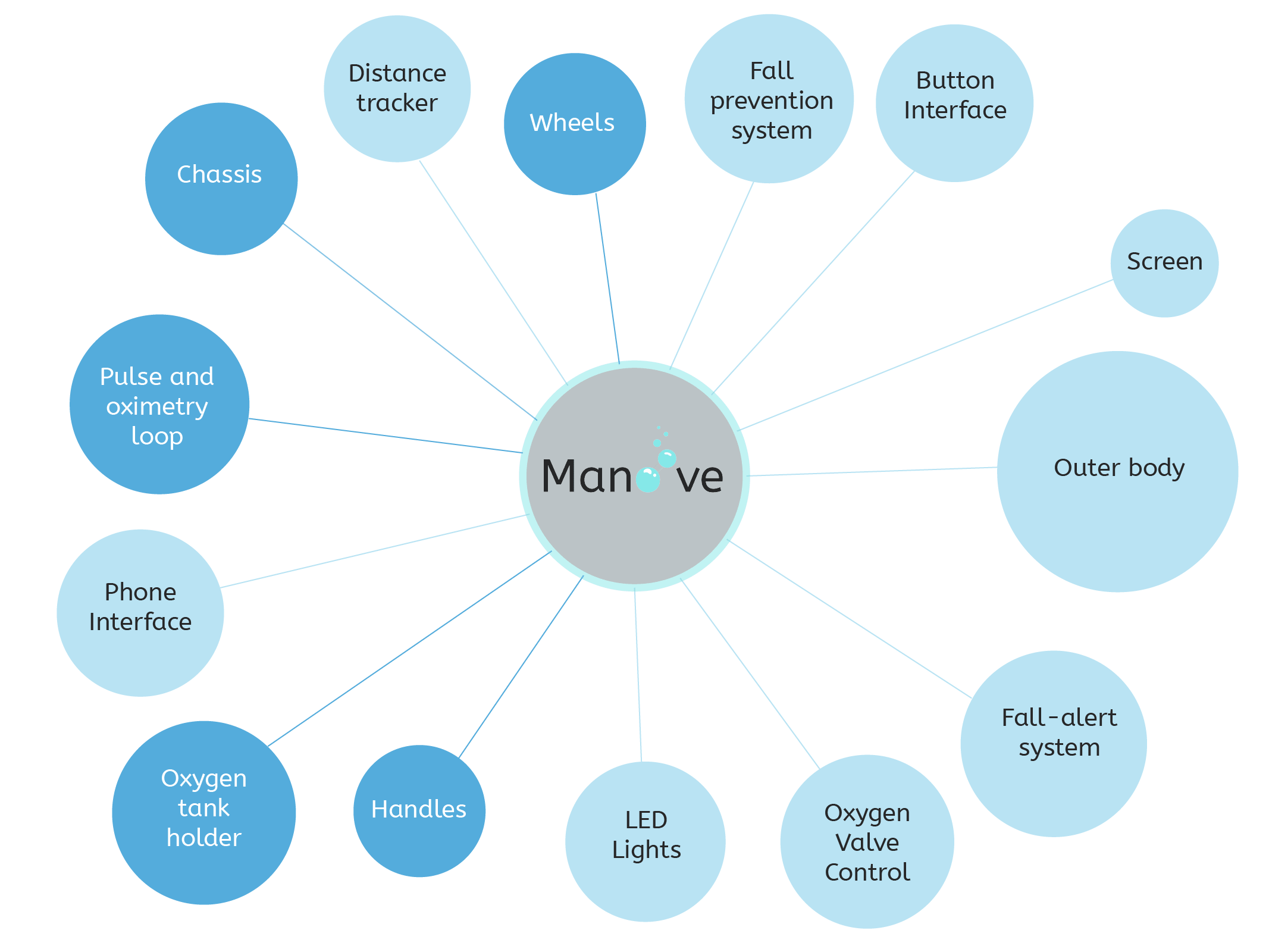
Brainstorming
Web Design
CAD and A/V Editing
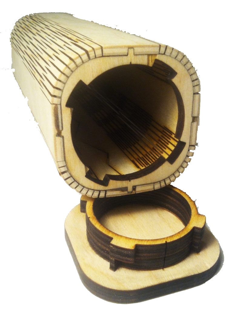
Computer controlled cutting
Electronics Production
3D Scanning/ Printing
Electronic Design
Computer controlled machining
Embedded programming
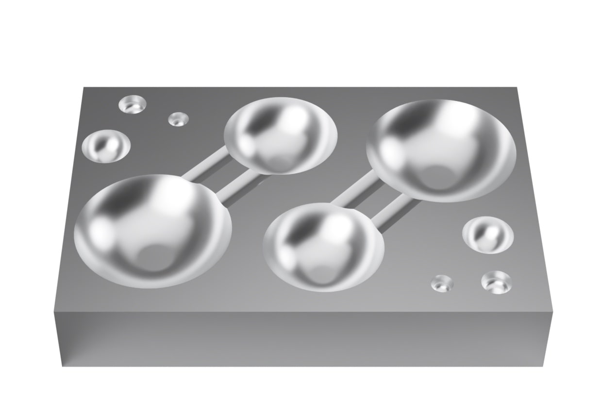
Molding and Casting
Input devices
Output devices
Applications and Implications
Networking and communication
Machine (Fablab 2.0)
Interfaces and Applications
Wild card week
Invention, Intelectual property and income
Project Management