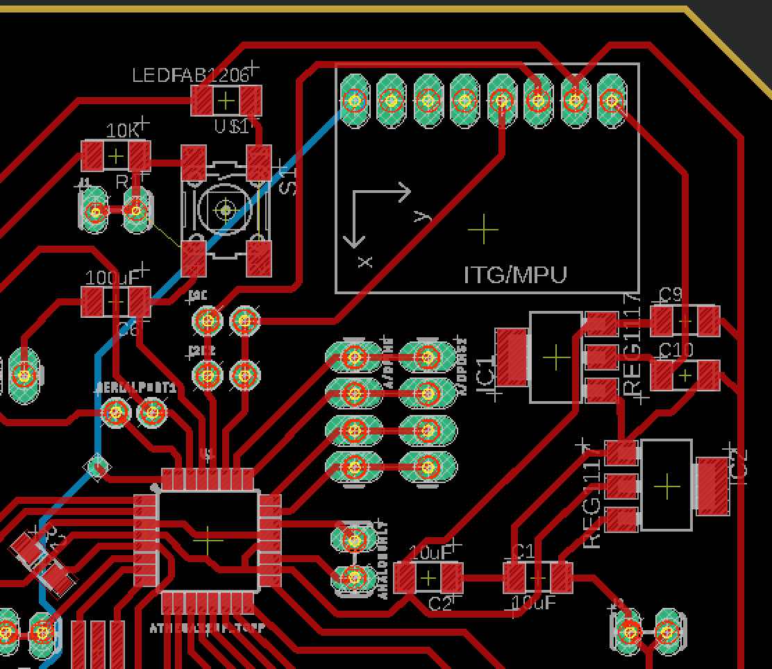
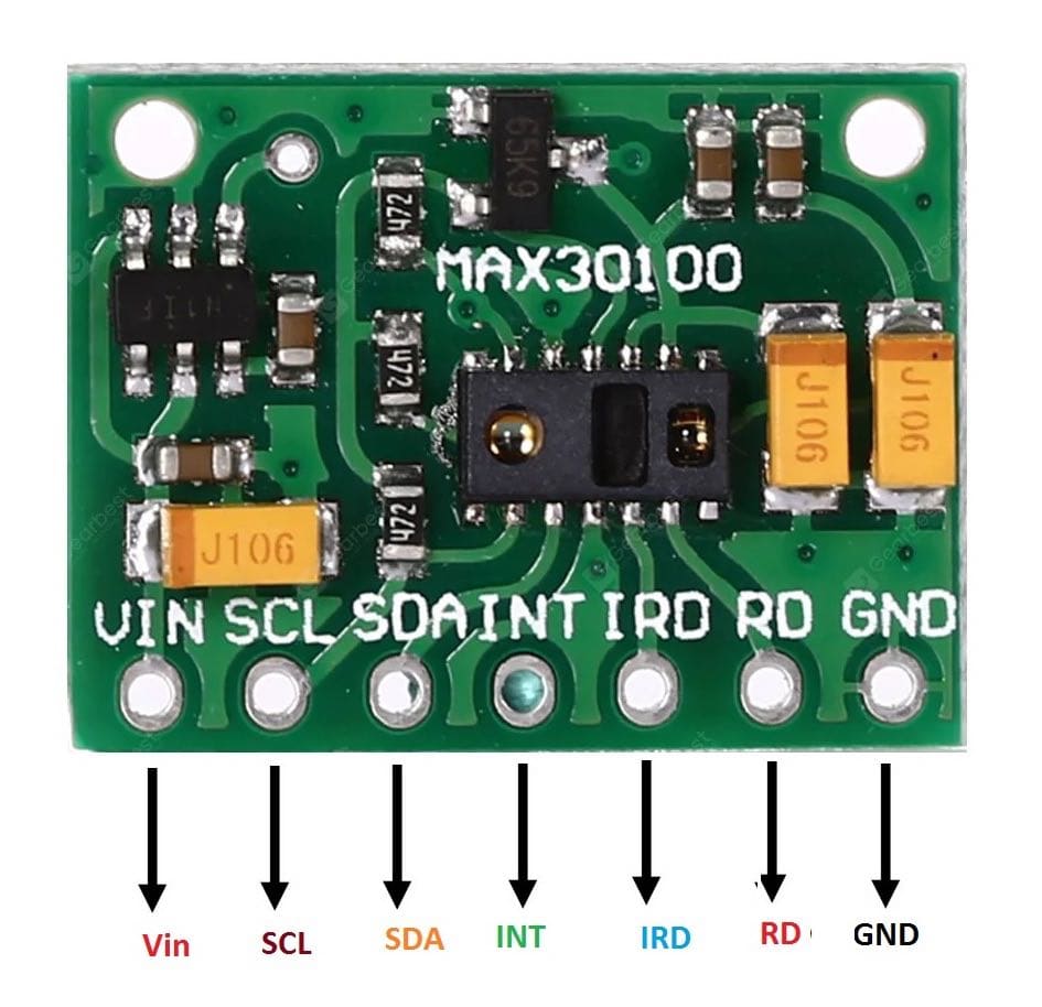
InputDevices

Week Overview
This week we had to learn about input devices and processing input data. I also developed the shield I will be using for my final project. However, some of the initial testing done for input devices was done on an Arduino Uno since my board took some time to develop and fabricate.

Designing my final project board
Since the development process I am following is spiral and I'm not sure how much functionality I will have time to include in my final project, I decided to make a modular board. The board I designed is optimal for stacking and testing. In other words, I will be able to manufacture an input and output board that will stack above it once testing is over. The design was inspired by Daniele Ingrassia's , which itself is a fabbable, arduino friendly development of the Fabkit. We didn't have any chips for FTDI to USB conversion, so I used a breakout board we had on hand. Also, I integrated the accelorometer/gyrometer board into the shield. This way the shield contains all the basic requirements, including a build-in sensore, with USB programmable capabilities. At first I used headers to plug in the FTDI shield, which will be removed once the stackable boards are fabricated.
My main goal was to have a minimum of 2 pins for I/O pins including I2C and Serial pins. While including 6 VCC and GND pins. This would allow the connection of atleast 6 sensors or actuators. Ofcourse, if stacking is achieved these numbers can be increased by using I2C to communicate to the sensor and other pins open for outputs and non-i2C inputs.
Although I was using a two-sided PCB, I decided to make the design applicable for 1-sided PCBs, this was done by including numerous 0 Ohm resistors as jumpers. However, even after attempting many different routing configurations, There was still one wire that was left unconnected. So I settled on having it connected by an external jumper for one-sided PCBs or using the bottom side on a two-sided PCB.
Routing attempts
Bottom/external jumper track
Version 1 board design
I named my board the Byrduino, and look forward to creating a git page to share the board with other makers around the world. You can see a picture of the first board on the right. Although the board looked fine, it wasn't burning the bootloader, so after hours of testing, I discovered I had used a different type of voltage regulator that is also in a SOT223 footpint however with switched ground and VOut legs. I therefore changed the design to a REG1117 voltage regulator with a SOT223 footpring and decided to integrate another 3.3V regulator to provide a more stable power source for the accelorometer.
My first board also made me aware of another problem, where I forgot to include RST pins required for stackability as well as initially burning the bootloader and programming the chip. I simply added a two pin header connected to the reset track and moved the surrounding components slightly to provide the required space.
This was the second version of my board design and my first successful byrduino. Some of the tracks look rough, this is because the endmill shipment was delayed in customs and I had to use an overused endmill. However, all tracks were connected well as I checked pin to pin connections using a multimeter.
For programming I used the FTDI to USB breakout board and specified the arduino pro on the arduino IDE as it contains the same chip and programs the Atmega328p seamlessly.

Calibrating and programming the accelorometer
The accelerometer/gyrometer chip I was using was a tricky chip to get started with from scratch, for someone with no prior experience. I therefore decided to start with the example and develop the example code to fit my requirements for my final project. I downloaded the and opened the example code. Depending on what you comment and uncomment, the code can provide the values of the gyroscope and accelerometer in different formats and references. I decided to choose the yaw pitch roll format as only the gyrometer values are require for my application.
The accelorometer board uses I2C to communicate with my board, this means initially it requires a voltage source, ground and connection to the SDA and SCL pins on my board. I might require an interrupt pin to integrate a standby energy saving function which turns on the walker if any movement was sensed. So I integrated these connections and the size of the chip on my main board as seen below. The connections are shown individually to the right.
In the example code, I removed all parts not required and left only the pitch and roll which reperesent the lateral tilting of the chip. Once the board was connected, I uploaded the ammended code to the board and opened the serial monitor to survey the values. A video of this can be seen below.

Reading HR and O2 levels
For the heart rate and oxygen levels, I'm using the SparkFun Max30105x sensor. It is a compact sensor for testing and prototyping and comes with details on how to connect/program it . The diagram to the right illustrates the pinouts. The heart rate sensor also comes with its own library which saves me time having to deduce my own signal processing code. The example code provided with the library, can be downloaded from the arduino library manager as shown below.
Similarly to the gyrometer, I changed the code to output the values I want to be able to further process them. two values indicate if HR and SpO2 levels are available while the other two values represent the actual data.
#include <Wire.h>
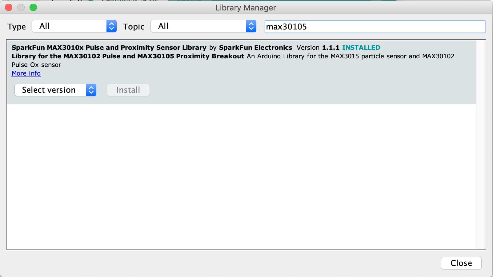
#include "MAX30105.h"
#include "spo2_algorithm.h"

MAX30105 particleSensor;

#define MAX_BRIGHTNESS 255

#if defined(__AVR_ATmega328P__) || defined(__AVR_ATmega168__)
//Arduino Uno doesn't have enough SRAM to store 100 samples of IR led data and red led data in 32-bit format
//To solve this problem, 16-bit MSB of the sampled data will be truncated. Samples become 16-bit data.
uint16_t irBuffer[100]; //infrared LED sensor data
uint16_t redBuffer[100];  //red LED sensor data
#else
uint32_t irBuffer[100]; //infrared LED sensor data
uint32_t redBuffer[100];  //red LED sensor data
#endif

int32_t bufferLength; //data length
int32_t spo2; //SPO2 value
int8_t validSPO2; //indicator to show if the SPO2 calculation is valid
int32_t heartRate; //heart rate value
int8_t validHeartRate; //indicator to show if the heart rate calculation is valid

byte pulseLED = 11; //Must be on PWM pin
byte readLED = 13; //Blinks with each data read

void setup()
{
  Serial.begin(115200); // initialize serial communication at 115200 bits per second:

  pinMode(pulseLED, OUTPUT);
  pinMode(readLED, OUTPUT);

  // Initialize sensor
  if (!particleSensor.begin(Wire, I2C_SPEED_FAST)) //Use default I2C port, 400kHz speed
  {
    Serial.println(F("MAX30105 was not found. Please check wiring/power."));
    while (1);
  }

  Serial.println(F("Attach sensor to finger with rubber band. Press any key to start conversion"));
  while (Serial.available() == 0) ; //wait until user presses a key
  Serial.read();

  byte ledBrightness = 60; //Options: 0=Off to 255=50mA
  byte sampleAverage = 4; //Options: 1, 2, 4, 8, 16, 32
  byte ledMode = 2; //Options: 1 = Red only, 2 = Red + IR, 3 = Red + IR + Green
  byte sampleRate = 100; //Options: 50, 100, 200, 400, 800, 1000, 1600, 3200
  int pulseWidth = 411; //Options: 69, 118, 215, 411
  int adcRange = 4096; //Options: 2048, 4096, 8192, 16384

  particleSensor.setup(ledBrightness, sampleAverage, ledMode, sampleRate, pulseWidth, adcRange); //Configure sensor with these settings
}

void loop()
{
  bufferLength = 100; //buffer length of 100 stores 4 seconds of samples running at 25sps

  //read the first 100 samples, and determine the signal range
  for (byte i = 0 ; i < bufferLength ; i++)
  {
    while (particleSensor.available() == false) //do we have new data?
      particleSensor.check(); //Check the sensor for new data

    redBuffer[i] = particleSensor.getRed();
    irBuffer[i] = particleSensor.getIR();
    particleSensor.nextSample(); //We're finished with this sample so move to next sample

    Serial.print(F("red="));
    Serial.print(redBuffer[i], DEC);
    Serial.print(F(", ir="));
    Serial.println(irBuffer[i], DEC);
  }

  //calculate heart rate and SpO2 after first 100 samples (first 4 seconds of samples)
  maxim_heart_rate_and_oxygen_saturation(irBuffer, bufferLength, redBuffer, & spo2, & validSPO2, & heartRate, & validHeartRate);

  //Continuously taking samples from MAX30102.  Heart rate and SpO2 are calculated every 1 second
  while (1)
  {
    //dumping the first 25 sets of samples in the memory and shift the last 75 sets of samples to the top
    for (byte i = 25; i < 100; i++)
    {
      redBuffer[i - 25] = redBuffer[i];
      irBuffer[i - 25] = irBuffer[i];
    }

    //take 25 sets of samples before calculating the heart rate.
    for (byte i = 75; i < 100; i++)
    {
      while (particleSensor.available() == false) //do we have new data?
        particleSensor.check(); //Check the sensor for new data

      digitalWrite(readLED, !digitalRead(readLED)); //Blink onboard LED with every data read

      redBuffer[i] = particleSensor.getRed();
      irBuffer[i] = particleSensor.getIR();
      particleSensor.nextSample(); //We're finished with this sample so move to next sample


      Serial.print(F(", HR="));
      Serial.print(heartRate, DEC);

      Serial.print(F(", HRvalid="));
      Serial.print(validHeartRate, DEC);

      Serial.print(F(", SPO2="));
      Serial.print(spo2, DEC);

      Serial.print(F(", SPO2Valid="));
      Serial.println(validSPO2, DEC);
    }

    //After gathering 25 new samples recalculate HR and SP02
    maxim_heart_rate_and_oxygen_saturation(irBuffer, bufferLength, redBuffer, spo2, & validSPO2, & heartRate, & validHeartRate);
  }
}

Setting up the rotary encoder
To measure the distance moved by the walker, I have decided to attach a rotary encoder to each of the front wheel axis. Initially for this week, I worked with one encoder, aiming to understand how it works and develop a basic framework for the code.
The encoder is constructed as seen in the diagram to the right. Two output sensing points are at equal distances from eachother. There are also VCC connected pads at equal distances placed on the rotary part. Once the pads contact the output points, a square wave output results 90 degrees out of phase between each output. Depending which output is sensed first, we can sense if the rotation is clockwise or anti-clockwise. d model of a half clenched hand.
I hooked up the roatary encoder to digital pins on the board as well as VCC and GND. Then I wrote the sketch below to read the values of the outputs and depending on the order to calculate it as a step. I also measured how many clicks the encoder turns, which resulted in 40. Meaning that each step is 18 degrees. Since the radius of the wheel is 55m, then the circumference is approx. 34.6 cm. So each step means the wheel moved 0.865 cm.
#define clk 3 //clock connected to pin 3
#define data 4 //data connected to pin 4
float counter = 0; //counter variable
int state;  //state variable to sense movement
int laststate; //variable to compare with previous state
float distancemeters; //value in meters

void setup() {
  // put your setup code here, to run once:

  //setup input pin modes
pinMode(clk, INPUT); 
pinMode(data, INPUT);
//begin serial at 9600 baud rate
Serial.begin(9600);
//measure initial state
laststate = digitalRead(clk);
}

void loop() {
  // put your main code here, to run repeatedly:
//read current state then compare with previous state to see if ther is movement
state = digitalRead(clk);
if (state != laststate)
{
  if(digitalRead(data) != state) //clockwise vs anticlockwise
  {
  counter=counter+0.865;
  }
  else
  {
    counter=counter-0.865;
  }
  Serial.print("you have moved ");
  if (counter > 100)
  {
    //if statements to convert to meters when over 100 cm
  distancemeters=counter/100;
  Serial.print(distancemeters);
  Serial.println("meters");
  }
  else
  {
    Serial.print(counter);
  Serial.println(" centimeters");   
  }

}
//save current state as previous state
laststate= state;
}

Files
Please find all the files required, if you feel like making your own:
File Link
Byrduino schematic
Byrduino board design
Rotary Encoder code
Accelerometer code
HR/SPo2 sensor code