
This work is licensed
under a
Creative Commons
Attribution-NonCommercial-
ShareAlike 4.0
International License.
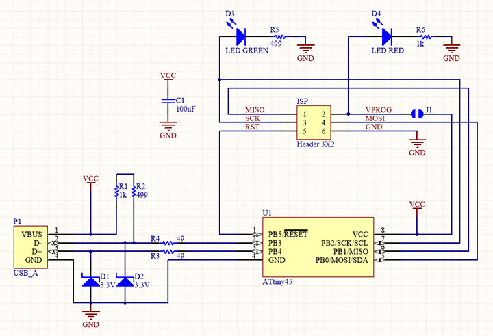
This week's assignment (02/14 - 02/21) consisted in milling our own PCB boards parting from a predefined design that we formated using the site fabmodules.org. We also worked then soldered the components to the board and programmed it following the steps of Brian. Find below the detailed process.While the diagram's below might seem a bit puzzling at first, they will become key references in the upcoming weeks as they indicate the direction of the current among other things.
This week students should have:
Shown how you made and programmed the board.
Explained any problems and how you fixed them.
Included a "hero shot" of your board.
I was in in a group with Jean-Baptiste, Javier, Andres & Daniel. The group project was
very helpful in giving us a sense of how the Roland SRM-20 works.
We first secured the PCB to the milling machine's sacrificial layer with some double-sided tape.
We had to make sure the tape stripes were completely flat and did not overlap so that the tool
can trace homogenously.
In the computer, we open Roland's VPanel software. This is where we set the home origin of our tool: X, Y and Z. We used a 1/64 toolbit for the traces and a 1/32 one for the outline. One of the trickiest parts is determining the Z home coordinate. The tools are very fragile (specially the 1/64 one) and if you move it along the Z axis too fast, it might break. It is best to move it down very slowly, one step at the time to make sure it remains intact and that the copper layer is coming out.

When we generated the G-Code for the outline, we did not realize that the trace for one of the sides
was missing. That is why we couldn't remove easily our sample board from the rest of the material and we had to break it apart. See section 2 for more information on generating the G-code for milling machines.
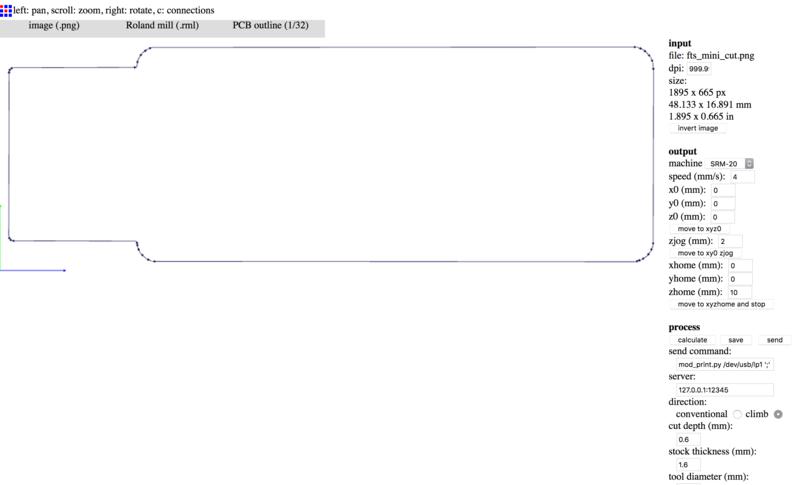
When you mill a circuit design, you start with a monochrome .png file: either one you have yourself created or one you have been given. In my case, and as mentioned above, I parted from Brian's .png design which can be found here. However, the SRM-20 cannot directly read a .png and the latter needs to be converted into G-code. This format is used by numerous digital fabrication machines such as milling machines or 3D printers. This code takes the shape of a text file containing the x,y and z coordinates of each point along the main paths of the .png design. In order to generate this code, I used the online tool developed by Neil Gershenfeld called Fab Modules. Below are a couple of screenshots showing the settings I used for generating my first G-code:
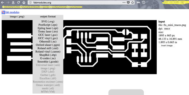
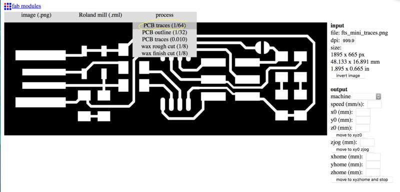
You need to run this process twice since you need two different G-codes: one for the traces and one for the outline. First go to the top-left tab labelled "image (.png)" to upload your .png file. Then, on the tab next to it select the output format as "Roland Mill (.rml)" and then go for the "PCB traces (1/64)" first.
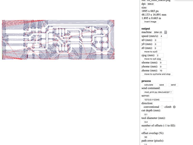
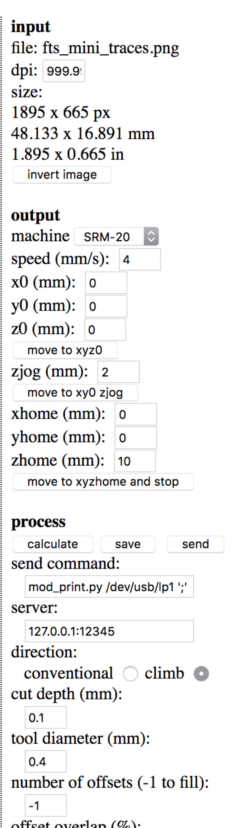
In the column on the right, under "OUTPUT" set the milling speed to 4 mm/s. The x0, y0, z0, should all be set to 0. zJog should be 2 and zHome should be 10. If you set the zHome to 0, the tool will scratch all the work it has done before when travelling to the zHome. In the "PROCESS" section, everything should default if you have selected the correct machine in the "OUTPUT" dropdown. However, if you want the machine to clean out all of the copper that is not part of the traces, then the offest should be set to -1. Then hit calculate. The software will then generate the toolpath in blue as seen below. If you are happy with the result, click on "SAVE" and the Gcode will be downloaded into your computer.
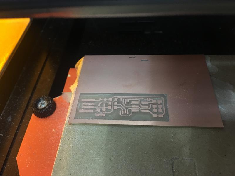
Below is the result once the small milling machine finished the traces of my first PCB:
Then I switched the 1/64 bit for the 1/32. I followed similar steps to generate the Outline's G-code. The settings are similar but make sure you select "PCB Outline (1/32)" in the third tab. The cut depth should be 0.6 mm and the stock thickness 1.6 mm.
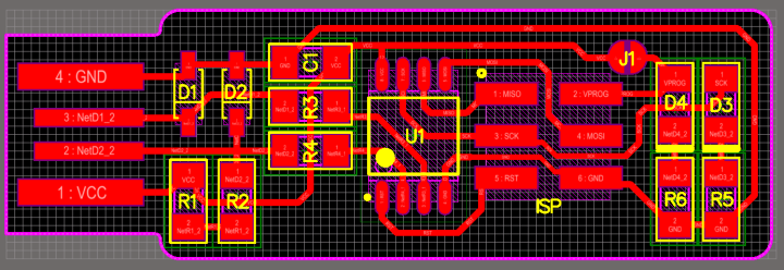
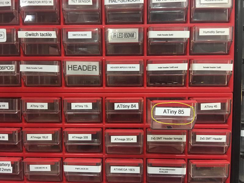
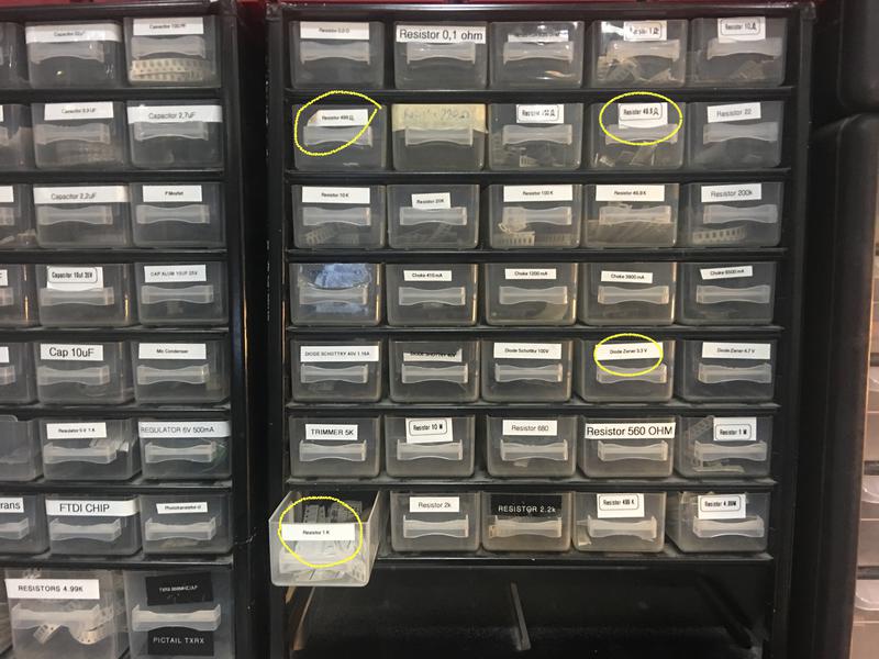
For building the FabISP, I used the following components:
1 x ATTiny 85
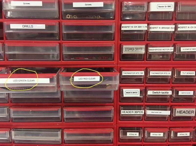
1 x Red LED
1 x Green LED
1 x Capacitor 0.1 microF
1 x 2x3 pinhead
2 x 1kOhms resistors
2 x 499Ohms resistors
2 x 49.9Ohms resistors
2 x 3.3V zener diodes
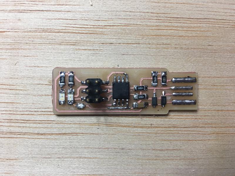
This was my first time soldering but I did not have many issues. Precision is key in this process and I found that quite meditative. I first used double-sided tape to secure the PCB to the board. I started by soldering first the microprocessor since it is located in the middle of the board. Then I kept on working outwards being the 2x3 Header the last component as it can be quite cumbersome due to its size.
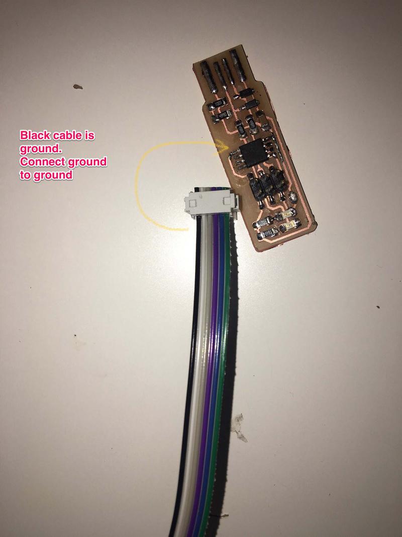
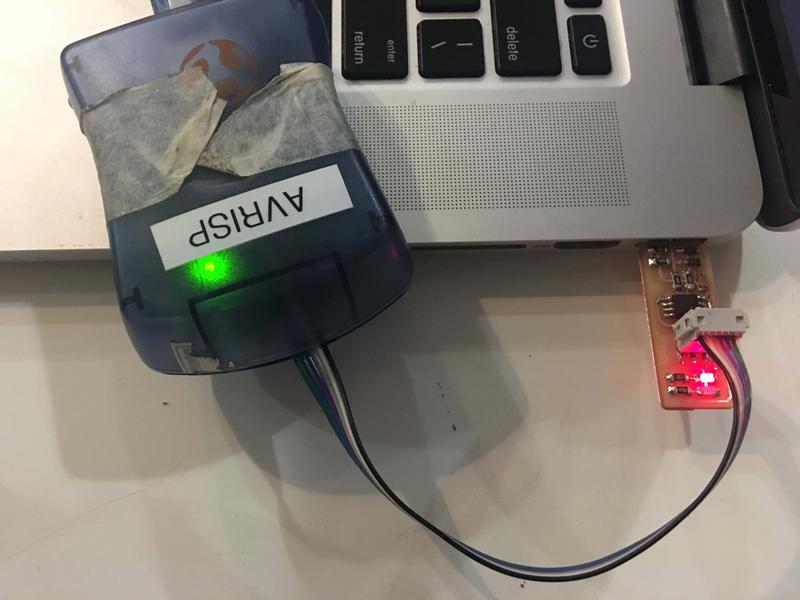
To program my USBtinyISP, I used the AVRISP II programmer available at the FabLab BCN. I connected it to the 3x2 pin header on my PCB. The other end of the programmer goes to one of the USB ports in my laptop and the USB connection in my PCB goes to the other as seen below:
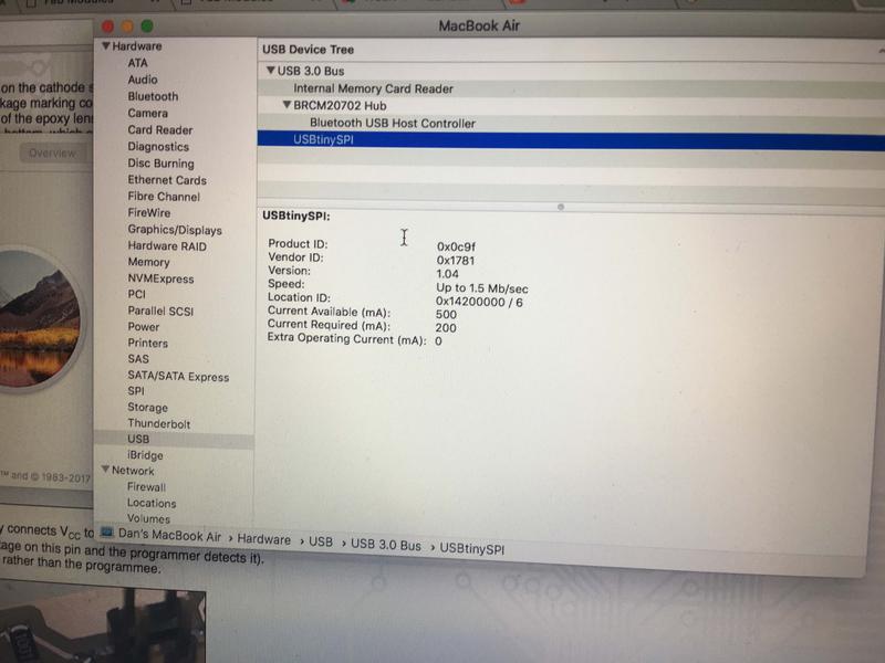
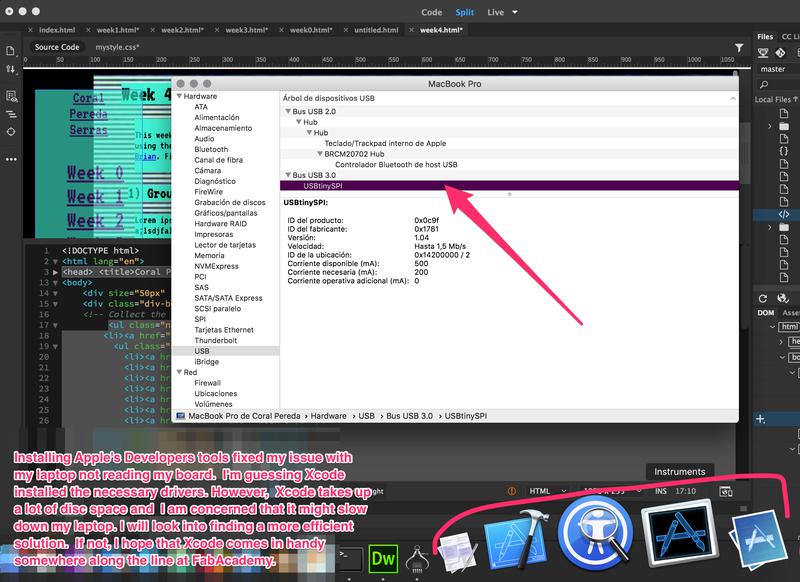
Programming boards has always been a bit of an issue for my laptop. This is mostly due to the fact that my USB ports have trouble locating the boards. In this case, the USBtinyISP wouldn't show up under the hardware section of my Mac's system report. However, as seen below, it did show up on my friend Daniel's laptop which led me to think that it was a driver problem:
I googled the issue and I read that installing Xcode delvelopers' tools could help. This did fix the issue, at least temporarily. I'm guessing Xcode installed the necessary drivers. However, these tools take up a lot of disc space and I was concerned that it could slow down my laptop. I will look into finding a more efficient solution. If not, I hope that Xcode comes in handy somewhere along the line at FabAcademy.
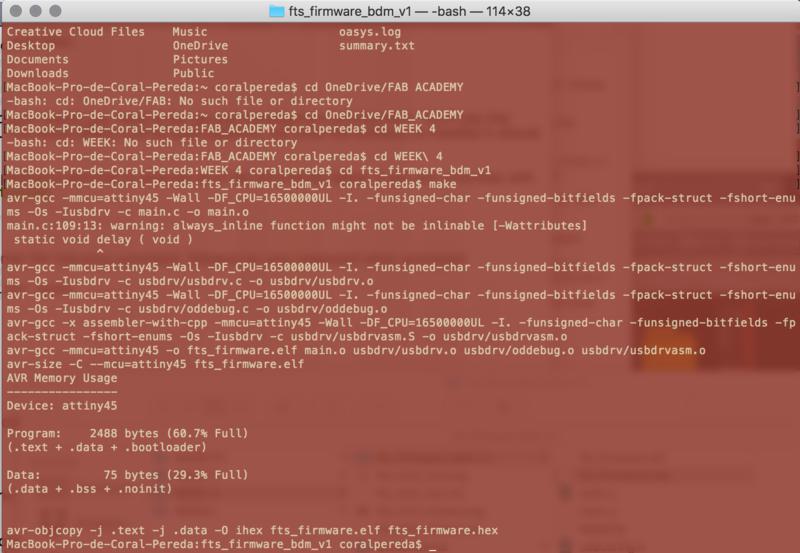
I then programmed my board following the steps below:
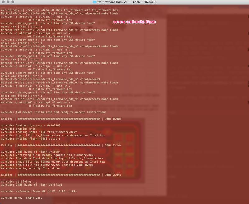
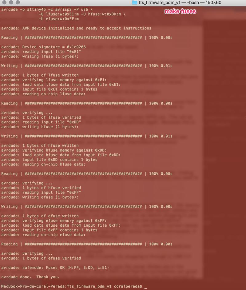
This was successful and I managed to program a couple of other boards using this ISP. However, it then stopped working. This is an issue that also came up with the boards of my fellow students. We think it is a problem with the USB connection. I tried fixed it by adding more solder to the copper stripes corresponding to the USB connector. I also created a base for it with an old debit card and attached it to the bottom of the board with double sided tape. This didn't work either. I would recommend for people to make a different FabISP and not the USBTiny because of the recent errors.