This work is licensed
under a
Creative Commons
Attribution-NonCommercial-
ShareAlike 4.0
International License.
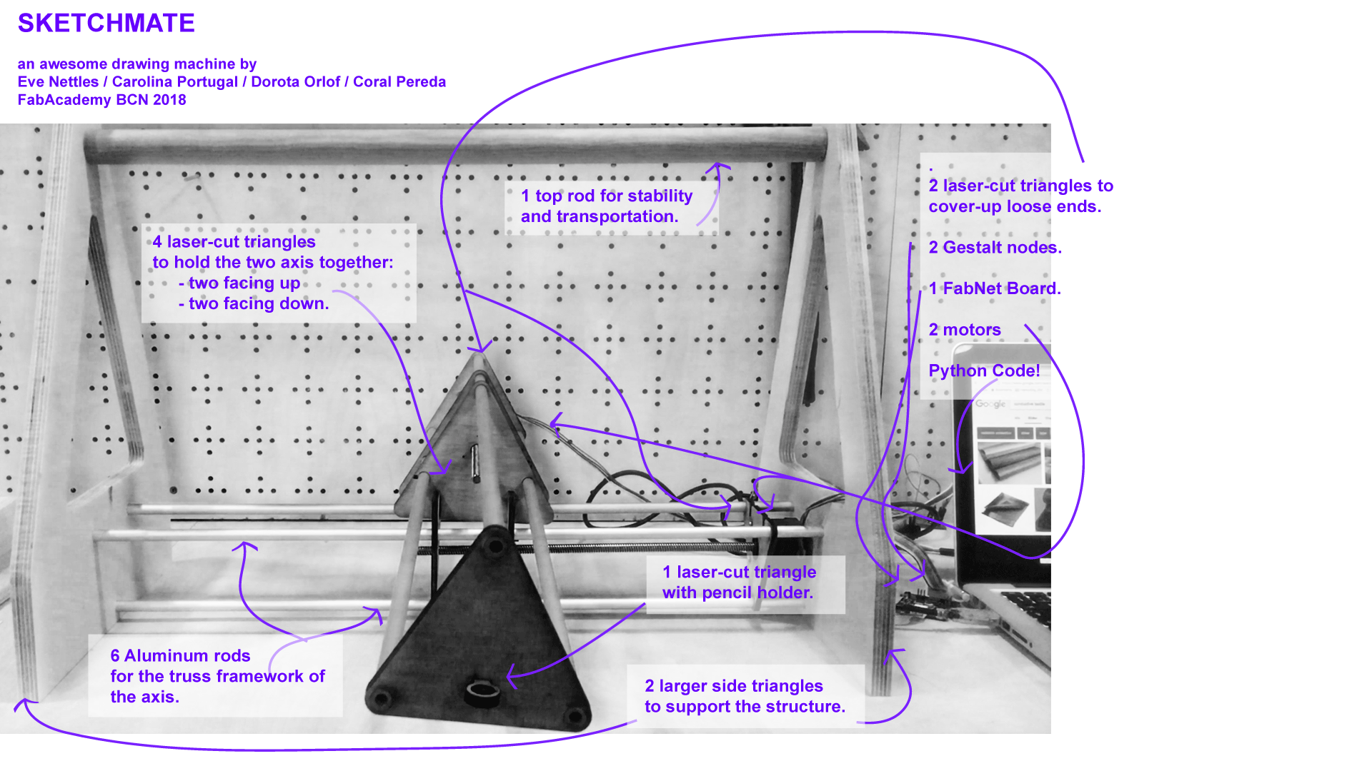
For the next two weeks, we will be making our own machine in groups of four approximately.
We will be working on a drawing machine. Our group website can be found here.
This week, students should have:
Explained your individual contribution to this project on your own website.
- Week1: Making parts.
- Week2: Controlling the parts.
- Stress (when you push) and strain (what happens to it and how it changes
after stress is applied to it).
http://archive.monograph.io/james/m-mtm
http://fab.cba.mit.edu/classes/863.17/Harvard/people/HonghaoDeng/project-10/project-10.html
http://chilipeppr.com/grbl
http://www.piccolo.cc/
- I built the index.html, the machinecss.css and about.html files for the main website. I based the css design on the css code by Arnau Tasies.
- I uploaded them to the repository. Screenshot of cloning repository and code.
- I created a trello board to divide the project tasks.
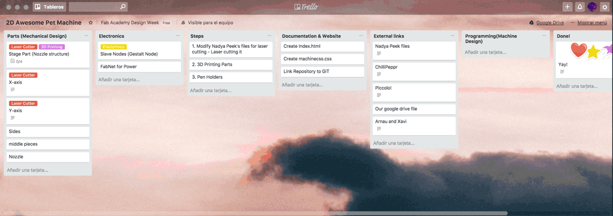
But in the end, we didn't end up using trello and moved our task organizer to a google drive document.
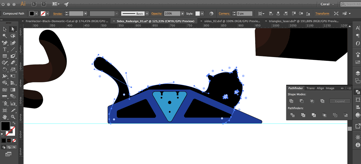
We worked on the files by team HonghaoDeng and decided to rework the designs. Each of us worked on a different part so that we could laser cut a quick prototype. I worked on the side supports by first importing the file of their side supports into Illustrator. I made a couple of modifications and fixed vectors' paths. I then exported the design as an SVG file and reimported it into fusion where I duplicated the sketch and preferred the .dxf file. For the conclusions drawn after cutting, please refer to our group website.
Once our cardboard prototype was finished, we decided to move on to plywood after making a couple of changes to some pieces. We wanted to personalize the design of the structure and for the side-supports we chose to go for a playful element. For the side-supports we wanted to go for a playful element and I adapted the triangular shape into a cat outline. In order to do so, I looked up vector images such as the ones on vecteezy. I ended up going for the image below:
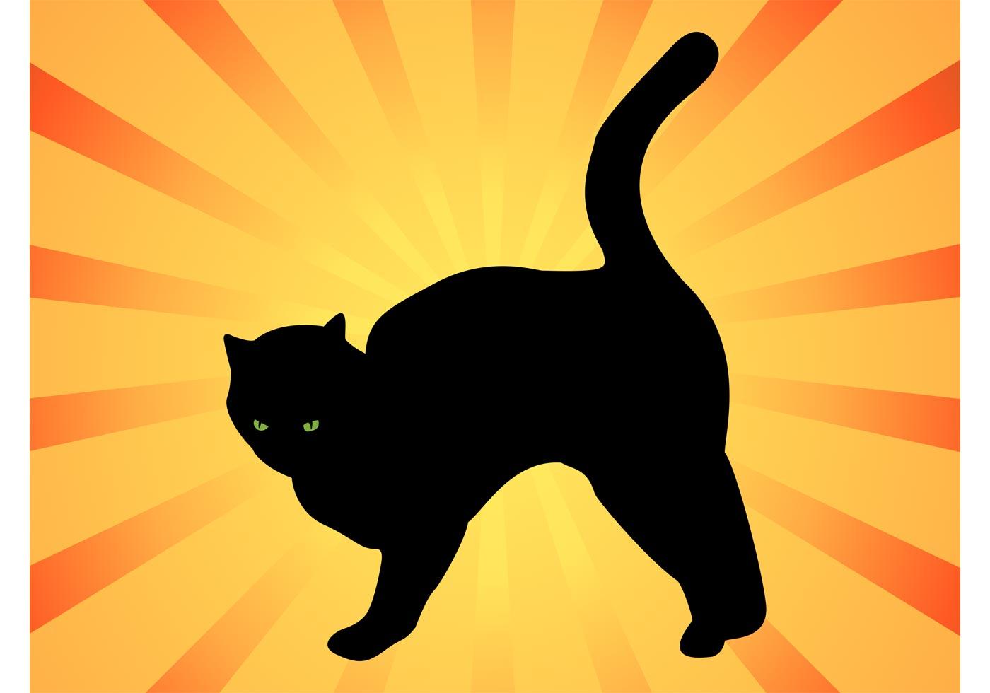
The image is licensed under Free Vector Design by: www.vecteezy.com.
 After observing the shapes on our laser-cut prototype (which can be found on our group website), we decided to keep the triangular shape consistent. We also noticed that the laser-cut plywood would not provide enough stability. We used the cnc machine to cut out simplified shapes for the side supports.
Today I worked mostly on documenting the work of our team in the group website. I selected a couple of images and compressed them. We really liked the idea of showing our progress through animated gifs. However, they are taking up a lot of space in our repository and as you can see, compressed gifs lose a lot of quality. For one of the moving images, I decided it was best to host it on vimeo as a .mp4 .
I worked on designing the eagle schematics and board for the FabUSB. The FabUSB would then be connected to the two Gestalt Nodes.
In the end we found out, that for mechanical design week, we did not have to create our own board and that we could use commercial ones.
Therefore we did not end up milling this PCB. Nevertheless, find below images and files for the design.
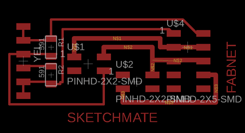
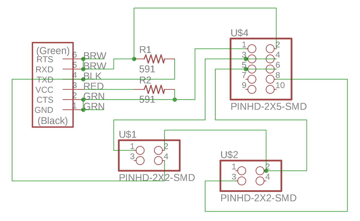
Sketchmate Eagle Schematic
Sketchmate Eagle Board
Today I have done some research on the g-code in order to summarize to my group the key points of how the code works. So far our machine works
using Nadya Peek's python library for the MTM machine. Throughout Fab Academy, we have often worked with .png files that we turn into G-Code
by using the CBA MIT Mods. Now I want to understand how we go from the g-code to a python program that allows our machine to draw a custom design.
The goal of going through this tutorial is to understand how the g-code output from our designs can be read in python by our machine.I have followed the tutorials on codeplastic.com. As of January 29th, 2019, the website seems to be down. An alternative explanation of what G-code is, can be found in this Ultimaker post.
We tried to find a way for the our machine to draw a circle. We found out that the best way to do so is to use the Python turtle library. First we used pip to install the turtle library. We did so by following the following tutorials:
- https://docs.python.org/3/library/turtle.html
- https://www.blog.pythonlibrary.org/2012/08/06/python-using-turtles-for-drawing/
- http://opentechschool.github.io/python-beginners/en/simple_drawing.html
Then we realized that turtle only prints designs on screen not on paper so we had to work something else out. I spoke to my friend, Huan Rui, who is a computational scientist and she helped us find a way to translate a circle into python coordinates.
find her code here . The code then generated the coordinates for a number of points that would make up the circle. Find below how I ran the script on my terminal and the outcome.
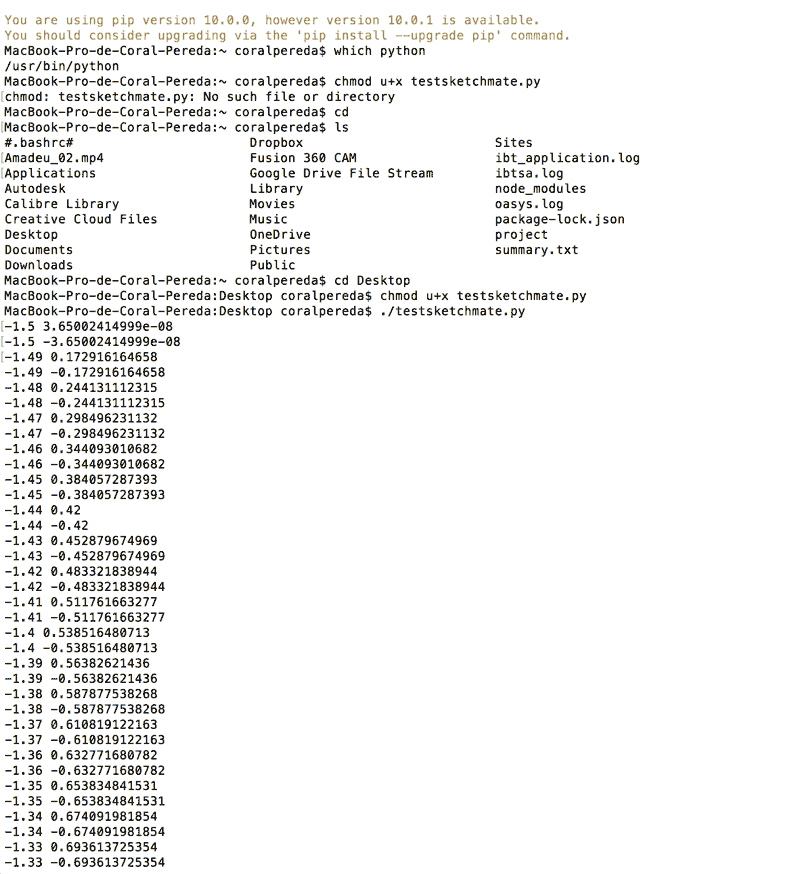
However, we could not plug that in directly into the machine. For more info on how we solved that issue please go to
our group website.
I collected the video files, structured and edited the video summarizing our project. I hope you enjoy it!
I also worked on the slide below.