
This work is licensed
under a
Creative Commons
Attribution-NonCommercial-
ShareAlike 4.0
International License.
For this week's assignment, I have followed the steps of the following Fab Academy Alumni: fab lab veritas
and Kyle Branchesi. As of January 31st 2019, his Fab Academy website under http://fab.cba.mit.edu/classes/4.140/Architecture/people/kyle_b/week-10.html is inactive. My goals for this week are "Measure something: add a sensor to a microcontroller board that you have designed and read it". I will do so by completing the tasks below:
Describe your design and fabrication process using words/images/screenshots.
Explain the programming process/es you used and how the microcontroller datasheet helped you.
Explain problems and how you fixed them.
Include original design files and code.
For this, I am torn between going for a motion sensor or a capacitance sensor:
1. motion sensor, more specifically the PIR Motion sensor, whose data sheet can be found here.
2. step response sensor: using the attiny 85.
The ATTiny45 has an internal clock of 1% nRC . If we need more than that, we will have to include an XTal or a resonator. Then we will not have to code into the board. Types of sensors:
- Motion
- Distance: Sonar
- Magnetic
- Light
- Acceleration
- Step response: two different types. 1) Loading: big resistor of at least 1M. 2) transmit - response (Tx-RX): They can also be transformed into pressure sensors if you include a relatively flexible material such as foam.
Library: blocks of code that we use regularly. we don't need to know what it includes exactly but we know what it does.
In fabAcademy BCN we use the Arduino library whereas Neil Gershenfeld uses the AVRC library
Arduino is rather the language (or even a library that is written in C++) and not only a single board but rather a family.
Arduino cc and arduino.org split and then arduino.org became the manufacturer.
The clock is usually followed by two capacitors.

A good link for arduino tutorials is the following: Learn Adafruit in arduino lessons for inputs.


I have been meaning to create my custom outlines for a board of my choice but I had never gotten a chance to do so until this week. For this week's Assignment purposes I just explored the possibility with the simple layout of the Step response board but my goal is to make this PCB for next week's output devices assignment. Find below the outline of the process:


I then click on pull from Fusion.
Below is my first attempt at generating the g-code:


There are a couple of issues with this code. As you can see in the first image, the tool path missed a couple of spots that I would have to scratch out with an x-acto knife. Additionally, I left the x0, y0 and z0 boxes blank instead of plugging in the number 0 in each of them. When I run this g-code the machine would stop as soon as it tried to move along the z-axis and the error dialogue box would pop-up in the computer monitor.
 The PCB showed at the top of the image above was the outcome of the g-code mentioned in this
paragraph. I then decided to switch to mods instead of fab mods since it is more precise:
The PCB showed at the top of the image above was the outcome of the g-code mentioned in this
paragraph. I then decided to switch to mods instead of fab mods since it is more precise:


 I had no major issues soldering the components into the board. I can clearly see an improvement between this week and Week 6.

In order to become a bit more acquainted with the Arduino libraries, I have first followed the tutorial Touchy-feely Lamp of the Arduino project book. It is also available through instructables. I also downloaded the CapacitiveSensor library by Paul Badger here. Since my fabtinyISP is not working even if I tried adding more solder to the USB connections and making a support for it, I have decided to use the Fab Lab Barcelona's avrISP. I will eventually follow the high-low tech tutorial entitled Arduino board as ATtiny programmer.


How to uninstall FTDI drivers in order to avoid conflict with MacOS Mavericks and newer pre-installed drivers.
Follow AskDifferent link .
This solution was however only temporary and the next time I reopened Ardunio the /dev/cu.usbmodem1411 was gone again .
Since I have been having issues with the ports , I decided to complete the assignment for now by using my Arduino UNO board.


If you look at the top right corner of the computer screen in the gif above, you can see how the numbers change from three digits to four digits every time my finger touches the strawberry.I do know though that my board works though since I have tried it on someone else's computer. However, that lead me to realize that the CapacitiveSensor library is too big for an ATTiny45 so I had to desolder it. I then replaced it for an ATTiny85 which I resoldered in its designated spot. The datasheets for these microprocessors can be found hereThis wasn't as cumbersome as I thought it would be. Of course, the board did not stay as clean as I had originally hoped but that's okay.

1. Once I finally managed to install the right FTDI drivers on my computer, I came back to do the programming I hadn't managed to do before. I used Arduino. First, I installed Paul Badger's library is installed. I just opened the example sketch called CapacitiveSensor, located in the last section of the examples dropdown menu.
2. When I first tried to upload the sketch by means of the menu option Program > Upload Using Programmer,
I got the errors below:

3. I decided then to make sure I had gotten the right pin umbers and declared the serial scope. I compared my code to those of Seonghee Kim and of Minsu Choi.
This was super helpful because I realized that the way to declare "Serial" library is by including the serial library at the beginning of my sketch.
4. That however still didn't fix the issue.
 Now the issue was in the line:
mySerial.print(millis() - start);
3. I realized that I had to create my own instance of the Serial function which I called
coralSerial and that's what the console meant with Serial was not declared. I declared it by adding in the following.
SoftwareSerial coralSerial(2,3); // Rx,Tx
This time, it did work! I managed to fix that issue by comparing my code to that of the Serial Software Example on the Arduino website.

Unfortunately I was not seeing any values in the Serial monitor when I touched the foil attached to my board. I was expecting to see similar values as I did when I tested the code with my ArduinoUno board. I double checked with my instructor and my colleagues and we couldn't figure out why that was happening. Here is a list of possible solutions and things to double check. I do believe we went through all of them though.
My final project relied heavily on the skills acquired in Week 10. I created a screen that acts as an input device. The screen contains eight capacitance sensors represented by eight copper vynil circles as outlined below:
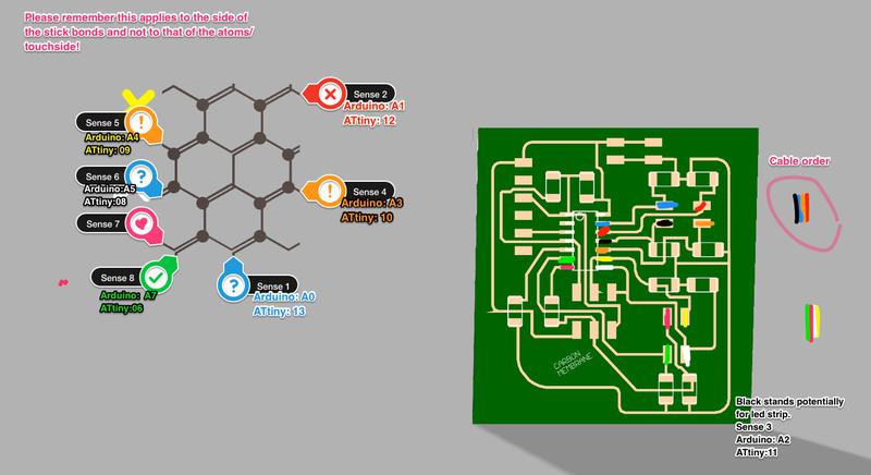
I based my code on the documentation by Pilu Caballero's. I then proceeded as follows to program the sensor connected to:
#include < avr/io.h > // Libraries previously installed
#include < util/delay.h >
#include < SoftwareSerial.h >


static uint16_t up, down;         // from Neil's Program
static uint16_t arriba, abajo;


SoftwareSerial mySerial(9, 5);


void setup() {
  pinMode(A2, OUTPUT); // Declaring the first sensor pin out from my board
  mySerial.begin(4800);
  //mySerial.println("Hello, world?");
}


void loop() {
  up = 0; // initial value for the states of sensor to up to 0
  down = 0; // initial value to 0 for down
  for (int count = 0; count < 100; ++count) {
    _delay_us(100);
    digitalWrite(A2, 1); //the pin out and his state
    arriba = analogRead(A3);
    up += arriba;
    _delay_us(100);
    digitalWrite(A2, 0);
    abajo = analogRead(A3);
    down += abajo;}


  arriba = 0;
  abajo = 0;
  arriba = analogRead(A4);
  _delay_us(100);


  if (arriba > 600) {
    mySerial.println(arriba);
  }


  _delay_ms(500);
}

This sketch was in communication with a processing program which was ran when the sensor read data. In the sections above, I knew my input device was receiving information based on the numbers that showed up in the Serial Monitor. Instead, in this, when the sensor read data, it would call to a processing sketch that differs for the one that is running in a loop. This is illustrated by the gif below.
For more details on the board used, please visit my Final Project page.
Eagle Schematic, Board and Arduino Code.
Final Project Arduino Code.