
This work is licensed
under a
Creative Commons
Attribution-NonCommercial-
ShareAlike 4.0
International License.
The goals for this week's assignment are:
Described your design and fabrication process using words/images/screenshots.
Explained the programming process/es you used and how the microcontroller datasheet helped you.
Outlined problems and how you fixed them.
Included original design files and code.
First, I considered building a satshakit which can be found here.
I soon realized that it that would be too time consuming so I chose instead to build
several output devices in one.
Types of Output devices:
LCD
LED
video: the board is quite trivial since it only has two resistors. The voltages need
to come very quickly.
Sound: you need mosfets. There are two types of mosfets: N mosfets and P mosfets.
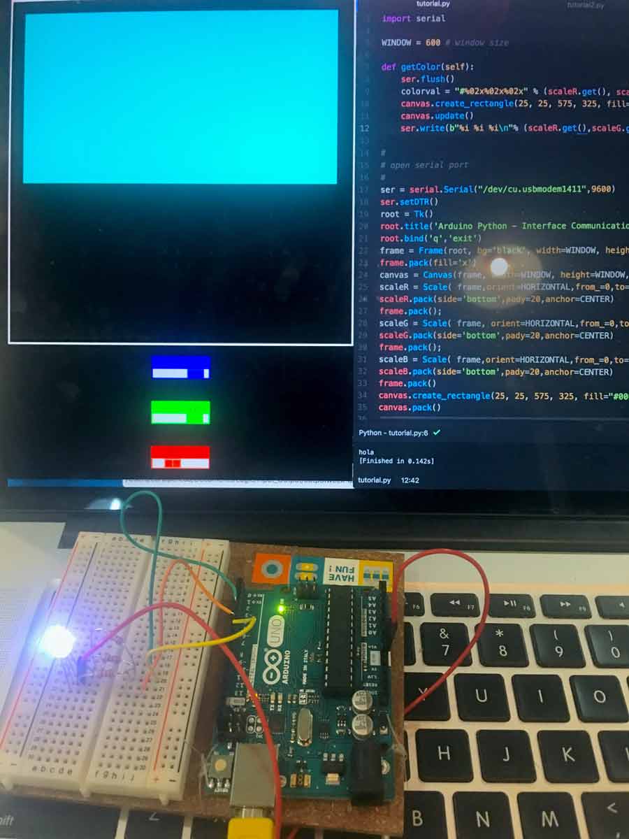
This week at Fablab Barcelona, we had an extra programming workshop focusing on Python. We used an Arduino Uno board, a breadboard, an RGB led and jumper cables. By using Atom
as a text editor and its Python script, we launch a visual interface that allowed us to control the color of the LED.
My initial goal this week was to combine both the input and video and sound output boards
in one single PCB. I am concerned that this might be too amibitious so for now I will just combine
video and sound in one output board. If this doesn't work, I will build the satshakit. For that I will use the ATTiny84 since I will need more pins than those
available in the ATTiny44 and also more memory that that. During Input devices week, I already had issues with the ATtiny45
since it does not have enough storage space to hold the Arduino capacitive sensor library. This link provides a good explanation of the function of Mosfets.
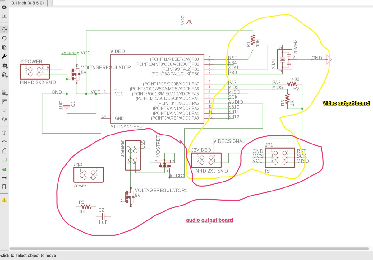
I decided to work on the video and audio schematics at the same time. I first started looking up
the components I wasn't familiar with such as the I2C, inter-intergrated circuit. I
soon realized that the I2C is actually a communication protocol that can be used by the Mosfet. Therefore, I2C and mosfet are not the same thing. The Mosfet is used to amplify sound signals.
The Pin out diagram of the ATTiny44 family was helpful when designing the routes
between microprocessor pins and components:
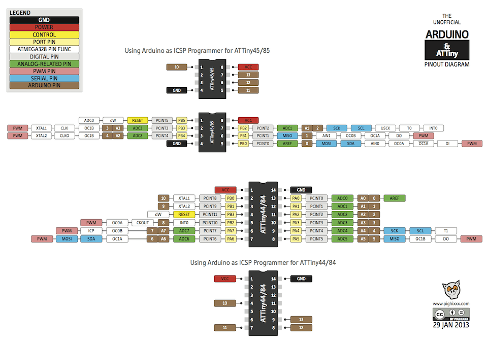
Image source: http://www.getmicros.net/programming-an-attiny44-using-an-arduino.php
It was also uselful to compare my traces with those of the satshakit mentioned above and with the Pinout diagram of its processor: the ATMega328:

Image source: http://saber.patagoniatec.com/atmega-328-micro-microcontrolador-chip-uno-nano-pro-mini-tutorial-arduino-arduino-argentina-ptec/
I first thought that I could use the same 2x2 pin header to output both video and sound since in Neil's example boards only two pins in each are being used. The same happens with the power 2x2 pin headers.Therefore the 5V voltage regulator and the 1uF capacitor do not need to be duplicated either. The audio output pins will keep the routing to a mosfet and the video pins will keep the 1000 Ohm and the 499 Ohm resistors. However, after trying ot connect both audio and video outputs to the same header I realized that the signals actually use three pins instead of two. I ended up then using two different 2x2 pin headers: one for video and one for audio.
At this stage, I had to postpone making a satshakit but replaced the ATTiny44 for an ATTiny84.
I also decided to apply the skills I learnt through last week's tutorial in making my custom shaped PCB. This website tutorial with Eagle shortcuts helped. This week I spent most of my time routing board's paths in Eagle. Something I learnt during this week is that it is totally worthwhile to keep your designs simple! Even if I really wanted to have most of the boards I made, look like the hexagons of graphene molecules, I realized that in the context
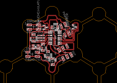
of FabAcademy it is not worth spending THAT much time routing the Eagle Board. Find below the design I sent to the milling machine:
 Another mistake I made was the last minute decision to add an RGB led. I really wanted to pull-off 3 outputs in one board! . I thought it would be as easy as adding a single channel LED but...
Read on in section 3 and 4!
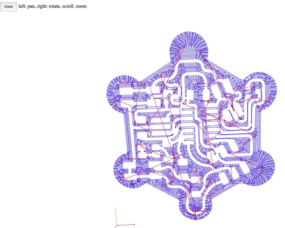
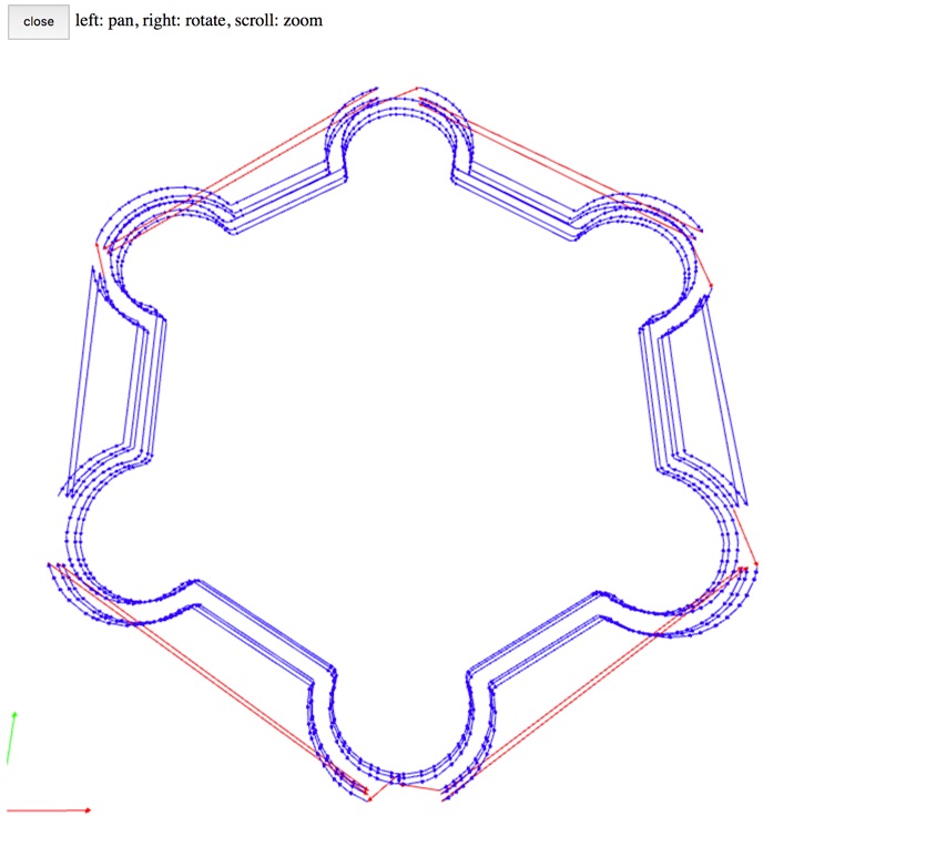
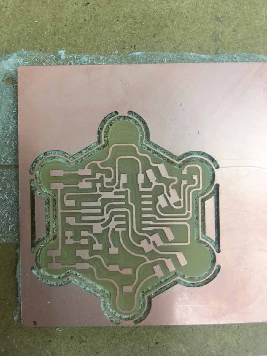
The images above show the tool path generated by the g-code in mods. As the first image shows,
I had to scratch out with an exacto knife some of the copper traces that appeared as united in the g-code.
In the second and third images, you can see that the milling tool follows the outline's stroke: one towards the inside and
once towards the outside of the board. During Week 13 I figured out how to fix this issue.
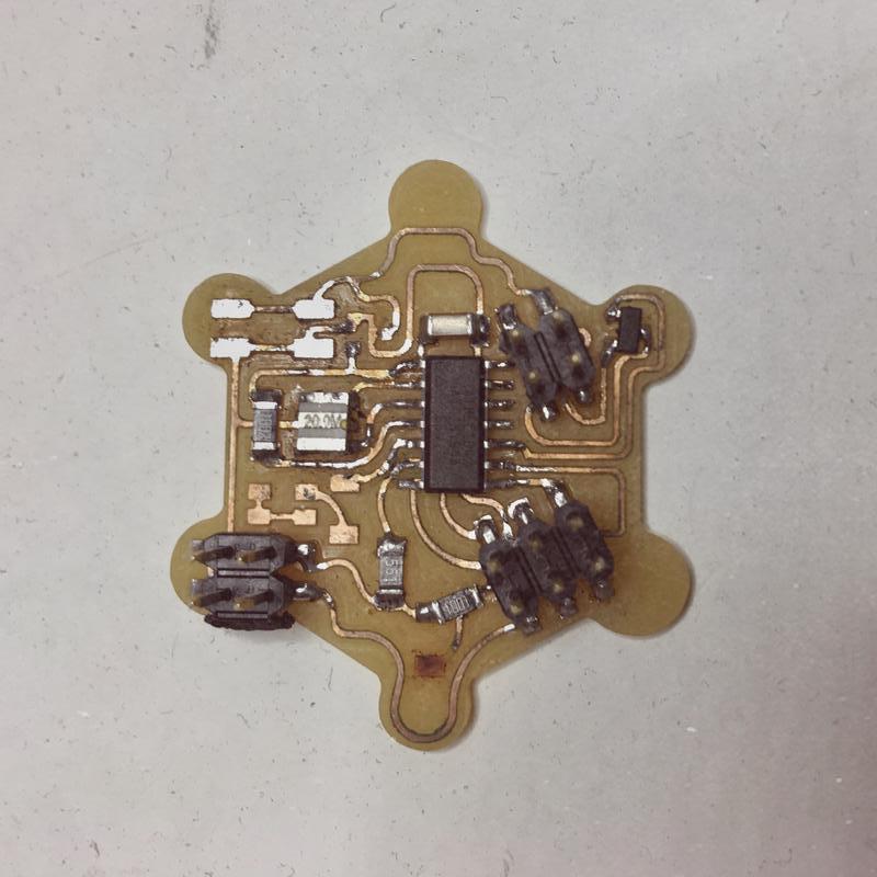
Now back to my LED error. I was trying to populate the board when I noticed that my RGB LED was connected to only one pin of the micro-controller and one single resistor. I then realized what that meant. I had only connected one of the color channels of the LED instead of three. As it was, my board would only have been able to output one colour whether red, green or blue. If I wanted to have the whole RGB spectrum, I would have had to redesign my board completely to include two more resistors connected to two other pins of the microcontroller. Since there were no visible issues with my
video and audio outputs, I decided to keep the board as it was.
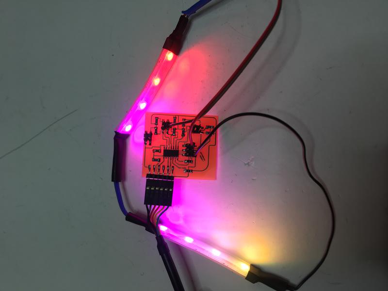
Given the needs of my final project, when I got to the programming part of the assignment, I decided to use my board to put an LED strip. I had the required voltage regulator in there! I remove the 2x2 pin header so that I could place a 9V battery holder in its place. As I did so, it started smelling like smoke. I immediatelly disconnected the battery. I realized that I had switched the spot of the voltage regulator for that of the mosfet thus burning my board completely. I had to then restart from scratch.
I designed by final project PCB to be a capacitance sensing board with eight input sensors. However, because of the layout of the screen, I only ended up needing seven of the eight sensors. This meant that there was a pin where Sensor 3 was supposed to live that wasn't being used.
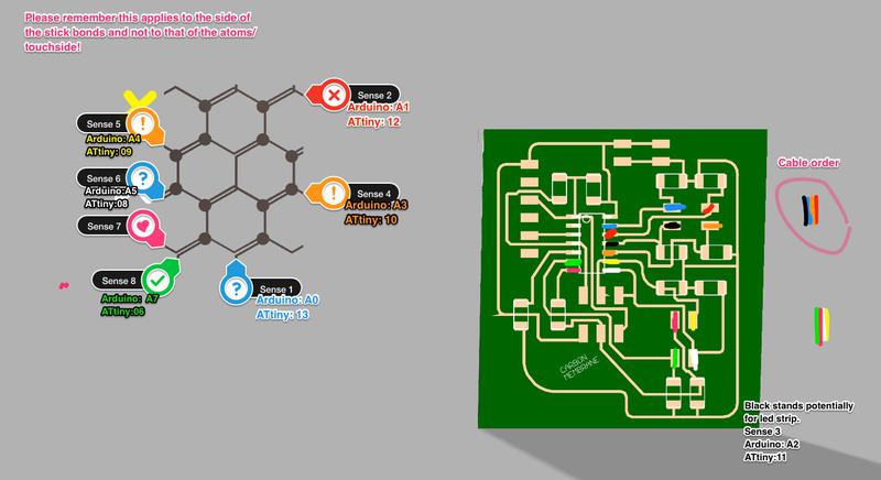 I then used that pin (corresponding to arduino Pin 8) as an Output pin. Note that using the Arduino Analogue pin numbering (in this case A5) did not work with the neopixels. I also replaced the 10 mega Ohms resistor for a 499Ohm resistor so as not to alter much the brightness of the led strip. Besides that, the code below worked fine.
      #include < Adafruit_NeoPixel.h >
#ifdef __AVR__
  #include < avr/power.h >
#endif
#define PIN 8

Adafruit_NeoPixel strip = Adafruit_NeoPixel(8, PIN, NEO_GRB + NEO_KHZ800);

void setup() {

pinMode(8, OUTPUT);
  strip.begin();
  strip.show();
}

void loop() {
  strip.setPixelColor(0, 255, 0, 0);
  strip.setPixelColor(1, 255, 0, 0);
  strip.setPixelColor(2, 255, 0, 51);
  strip.setPixelColor(3, 255, 0, 102);
  strip.setPixelColor(4, 255, 0, 153);
  strip.setPixelColor(5, 255, 51, 102);
  strip.setPixelColor(6, 255, 102, 51);
  strip.setPixelColor(7, 255, 153,0);
  strip.show();
}
Eagle Schematic
Eagle Board
Final Project Output Code. Please keep in mind that this Arduino sketch contains only the code for the output device of the final project and not the complete code.