Classes and Final Project
week1 : principles and practices, project management
week3 : computer-controlled cutting
week4 : electronics production
week5 : 3D scanning and printing
week8 : computer-controlled machining
week13 : networking and communications
week14 : machanical design, machine
week15 : interface and application
week16 : applications and implications
Final Project
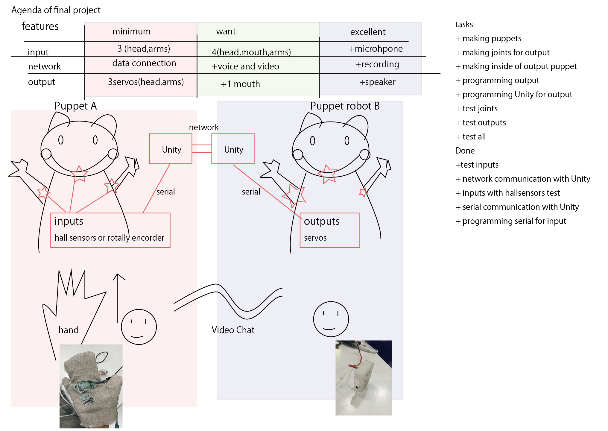
uPuppet
These toys synchronize each other so when one’s body is moved, the other one’s body will be moved automatically as well, and the opposite is also same.
I've been studying an interaction design since I entered the University. My research is forcusing on a co-operated communications. The problem is that I have some knowledges about how to make softwares and hardwares of communications, but still I don't know how to make my devices be attractive. For example, What the best materials for making bones of toys, skins and eyes are.
Therefore, I want to make whole device including softwares, hardwares, materials, designs and structures.
--11/3 updated--
Since the FabAcademy started, some persons asked me how it manages to moving when both persons try to move their dolls. I think it can be solved with setting a priority (Like a server and a client), but then one question came to my mind, does it make sense that both persons in over a distance can intaract the same thing? Normally, when one person and the other person meet in physical world, they can see same things and intaract with them. The first motivation is that I'd like to make that circumstance over a distance. However,
--20/4 updated--
After the thingking again, I changed the final project little bit. Thinking about communicating to other people over the distance via the internet, the most common way is a face chat such as Skype and google houngout. We can use the face chat everywhere everytime, but I think we don't feel that another communicated person shares a same circumstance. Then my proposal is that if we feel that there is a real person which is over the distance, we can make radically new ways to communicate each other.
To that, I think controlling the puppet from a distance is a good way to feel like "you are here". Compared to play with dolls, playing with the puppet can be played more human like movements.
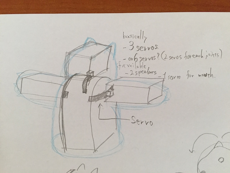
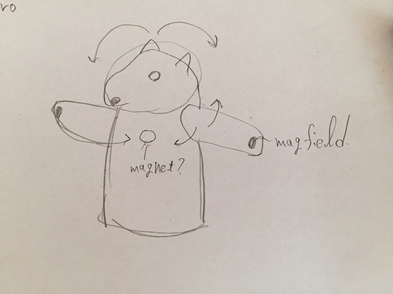
About outputs of the puppets, I think at least it should have three joints for movements. One for a head joint and two for both of arms. For inputs, first I think the movements would be detected by pressure sensros (capasitior sensors), however I didn't try yet, but I suppose to use magnetic sensors could measure the angles of arms and head. When I tried it, I add the description.
-- 19/5 updated --
Work in 15th week
This week (15th week), first I made a plan to fnish my final project.
Before this week, mainly I finished the programming part of my final project. For example, input and output part. However I didn't make any joints, measuring part and puppet bodies. So in this week, I focused on these parts and tested it works or not.
I already made 3 hall sensros and the board for the input puppet. The hall sensors can be used with magnet and you can measure the distance between them. I would like to use it to measure the agle of head and arms, so I sewed magnet and hall sensor on fabric. Here is the movie and you can see the box in Unity rotating by the distance between them.
In this week, iaac was very busy and I couldn't use Makerbot 3D printer, so I used the resin 3D printer instead of that (form1). Making a joint with servo was little bit difficult for me because I didn't know mecanical design and I had no idea how I can make it. Ferdi suggested to serach "robot arm servo" in Thingiverse and GrabCAD. Yes, I found some good examples for my servos (HK15178) and based on that, I made joints with Solid Works. Here is the video.
In this joint, the part of servo joint gonna be in puppet body, and the other part gonna be as a head. The servo and joint are pretty good to work and I can controll it with Unity as well.
Globe
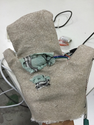
After that, I made a globe for input device. I attached the magnet and hall sensor on it. I didn't test it yet, but when I twist my hand, creases are appered. So probably it works but not good.
Next work is that trying to test the globe and communicate with Unity. After that, I'll make whole output model.
17th week progress
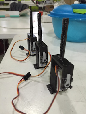
This week, I made the three joints for servos with 3D printer. These are gonna be the joints for the head and two arms. The long stick on the joints is as the bone in the puppets.
In 18th week
All of files are at below.
Before this week, I had made these stuff.
But I know, even if I prepare these modules, It doesn't mean that all of these can work correctly. And most of problems can occured in the connections. So the steps should be like that trying each two modules (for example, Unity application and Input board) and if these work, then combine all.
-- Input --
For input device, I already made the glove which is for inside of puppet. The rest of works were that making outside of puppet and put the board and glove in the puppet. I choosed the producted puppet for input (If I had a time, I'd like to make my owm puppet, but I couldn't manage it.)

-- Input with Unity --
The board has three hall sensors so it needs to send three data to Unity. I used the serial communcation with those applications, in the serial, I used some recognization signals for data. In Arduino code, it sends "1,2,3,4, high byte data1, low byte data1, high byte data2, low byte data2, high byte data3, low byte data3". As I desribed in previous Unity, Unity can only run its code 60 times in every 1 second and it's too slow to read the serial data. Because of that, I made a thread and communicated with serial. I also changed serial communication speed to 4800 for more stable communication.
-- Network Communications --
Unity has the network communication functions, so it's easy to syncronize some data. When you attach the component which is "NetworkView", then the object gonna be syncronized via the network. I used this function and send/recieve the data (three analog data) between two application each other.
-- Output with Unity --
For me, first I thought output is just same as input, so it's easy to make. But when I tried it, I understood this is the most complicated part in my project. In output part, the Unity has to get the data from network, convert it to the readable data for servos and send it to the output board. Getting data from network is easy, just It reads the data from network objects. However, C# can only send String or byte array data as the serial to the board. The board also had the problem that it can only read serial as the charactor value. So, I need to convert "Int data" to String or Byte and manage to make data be readable. First I used the byte and read it, but the serial monitor shows just random value, then I use String in Unity and char in board. Bacause of that, I converted the int value to char value and sended it in serial. For recognization, I put 'A' charactor in front of the data and then sended data1, data2, data3 in charactor.
-- Output --
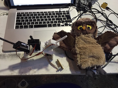
I used three servos for outputs. One is for the head, others are for arms. In FabLabBarcelona, there are too many students and I could suppose to the 3D printers gonna be really crowded. To avaoid that, first I did 3D printed works, then forcused on the mechanics part. I already made three joints, so my work was to make the frame of output puppet. I put the joints on the frame and fixed with screws, also I sticked the board inside of the frame. For outside of the puppet, I covered the frame with some feathers and the puppet was going to be fluffy. First I thought I should buy the outside of the puppet(I mean its "skin"). But there is not any puppet and dolls skin that match to my puppet, so I tried to make my own puppet's "skin". Thanks for Anastasia, she teahced me how to design fabrics things in Rhino, I could design it in Rhino.
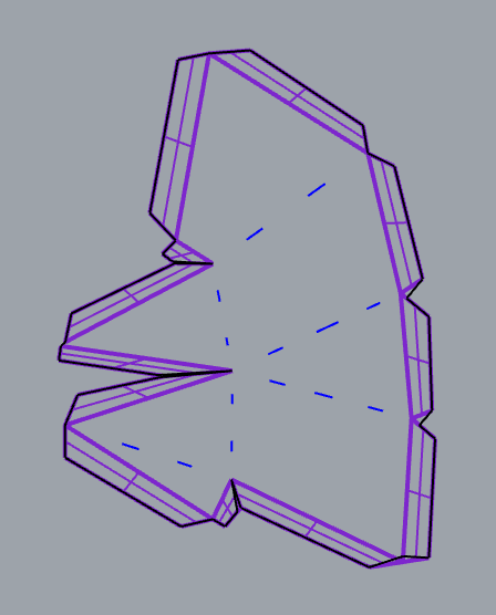
- How to design the 3D fabrics with Rhino
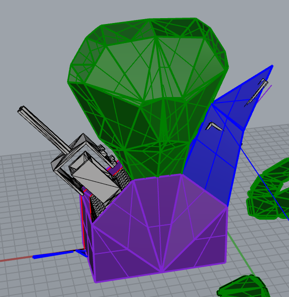
1: First, design your surface. It should be 3D (otherwise it doesn't have any space for feather), and all of its surface should be triangles.
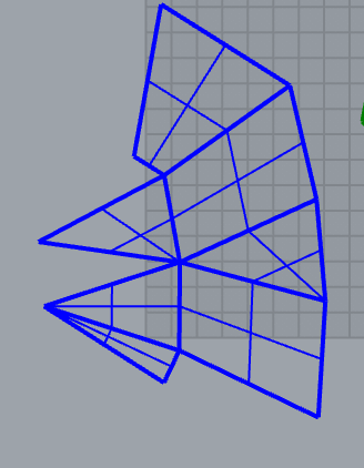
2: joint all surface that you want to unroll it. In the picture above, I showed the arm part (Blue color). Then, select it and run unroll command. Please check out "explode" and "Keep properties".
3: Then you can get the unrolled plates. To assemble it, it needs to have ears. just make some squares along the plates. The enough height is 5mm~1cm.
4: Draw lines arround them. Then you can get the outside lines. If you want, you can save it and cut it with laser cutter. But usually we draw some guided lines in order to avoid complex things.
5: cut it with laser cutter. I cut the wool fabrics. First I supposed it's gonna be burned, but surealy it worked well.
This is the one of a result.

After all, I was ready to combine all stuff. Fortunately there was not any problems and it worked well. Here is the result and program, design files.
The sources and files are on GitHub.
Conclusion
What you did: I made two puppets for person's communication in long-disntace. One is for input, it sends the angles of arms and head to the other. The other one is for output, it follows the movements of input deivce. I bought the puppet of input, but all of other stuff (electronics, softwares and output puppet) are made in FabLab.
What it does: When you connect it to your computer, start the software and write your device name and the other person's IP adress and port, you (and the other one) can communicate with these puppet in long-distance.
What worked, and what didn't: The three movement parts are wokring really well, but I couldn't manage to make microphone and speaker parts.
What you learned: I learned a lot of things from my final project, how to desgin electronics boards, how to make applications in Unity, how to design fabrics with Rhino to cut it with laser cutter. Especially to make 3D model for servo is really surprise for me.
All files are here
You need
The MIT License (MIT)
Copyright (c) [2015] [Taichi Hisatsune]
Permission is hereby granted, free of charge, to any person obtaining a copy
of this software and associated documentation files (the "Software"), to deal
in the Software without restriction, including without limitation the rights
to use, copy, modify, merge, publish, distribute, sublicense, and/or sell
copies of the Software, and to permit persons to whom the Software is
furnished to do so, subject to the following conditions:
The above copyright notice and this permission notice shall be included in all
copies or substantial portions of the Software.
THE SOFTWARE IS PROVIDED "AS IS", WITHOUT WARRANTY OF ANY KIND, EXPRESS OR
IMPLIED, INCLUDING BUT NOT LIMITED TO THE WARRANTIES OF MERCHANTABILITY,
FITNESS FOR A PARTICULAR PURPOSE AND NONINFRINGEMENT. IN NO EVENT SHALL THE
AUTHORS OR COPYRIGHT HOLDERS BE LIABLE FOR ANY CLAIM, DAMAGES OR OTHER
LIABILITY, WHETHER IN AN ACTION OF CONTRACT, TORT OR OTHERWISE, ARISING FROM,
OUT OF OR IN CONNECTION WITH THE SOFTWARE OR THE USE OR OTHER DEALINGS IN THE
SOFTWARE.