Electronics Design
Based on the requirements I set for myself in Week 15: Applications and Implications , I set about designing the control PCB for the clock.
Originally, I hadn't been sure what processor configuration I was going to go with. I had heard that the ESP8266 wasn't particularly reliable when it came to driving WS2812b LEDs directly. To work around this, I was planning on either:
-
Using a PSoC4 for most parts with an ESP8266 just for the networking
-
Using an ESP8266 for most parts, with just an ATtiny85 for driving the LEDs
As luck would have it, I noticed that the NeoPixelBus library was now listed as being supported in the Arduino IDE for the ESP8266. I figured I would give it a try, as being able to run everything on the ESP8266 would save a lot of hassle! If it turned out to be unreliable, my backup plan was to add an ATtiny85 as an I2C slave to the design, and use it to drive the LEDs.
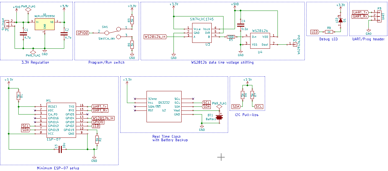
The schematic for the control board is pretty self explanatory - it's made up of sub circuits I've already made elsewhere for the class. I've just noticed that I have the LED round the wrong way in the schematic - woops! Luckily I didn't follow the schematic to the letter when I was stuffing the board. It's been fixed in the schematic but I'm too lazy to create a whole new image for such a minor mistake.
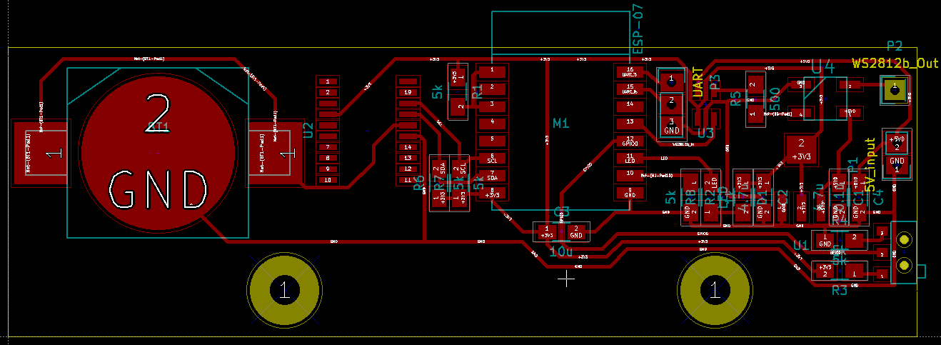
The PCB layout was a relatively painless affair thanks to the discrete sub circuits. Two things worth mentioning:
-
The version below is my final version. The rest of the pictures in this post show a version which has much smaller mounting holes.
-
The footprint for the DS3232 is also compatible with the DS3231
Mechanical Checks
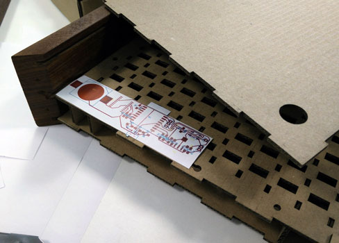
As with all my boards, I printed it out to scale to check all my footprints. I also used it in conjunction with the cardboard word clock to make some initial decisions about how I was going to mount the PCB inside the clock.
Making the PCB
Happy with the design, I cut it out on the Denford PCB engraver. Total cut time was in the region of half an hour.
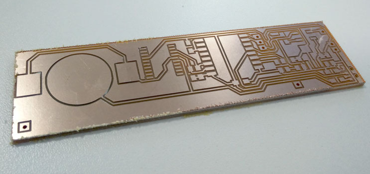
Just for interest, here's a comparison of a PCB cut with a brand new bit and one cut wit an old (and potentially broken) end mill. Both have had their outer edge cleaned up, but no further post processing.
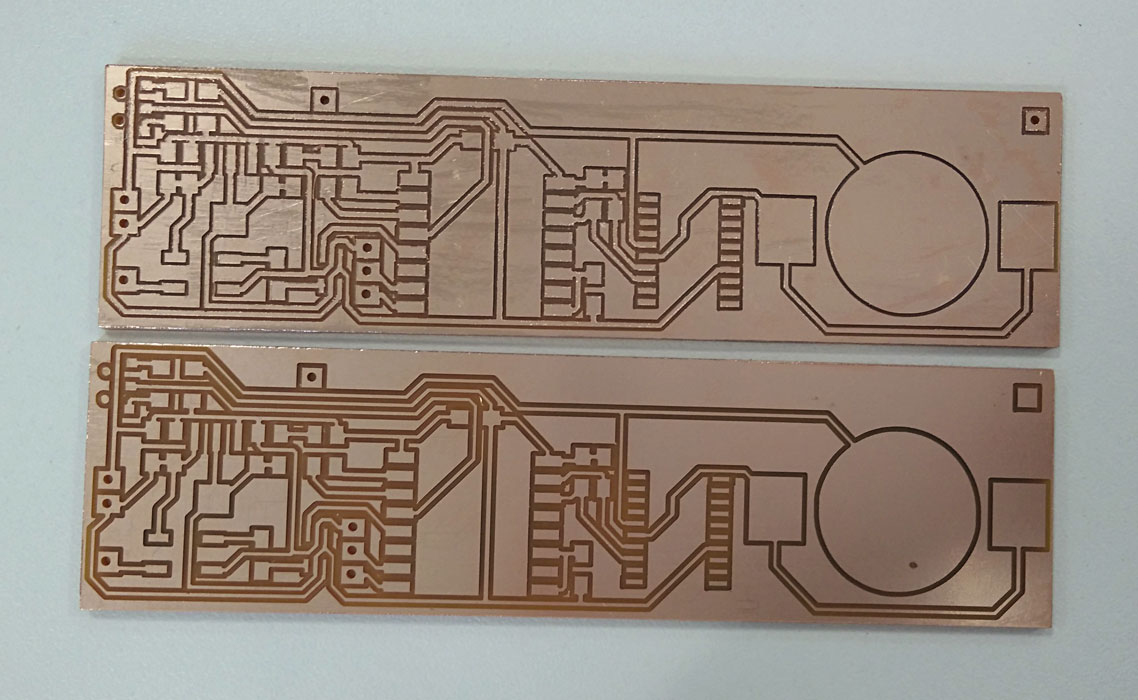
The top board was using an old bit and had a LOT of burrs. It would have needed a significant amount of work to clean it up. In comparison, the bottom board was cut using a new endmill. It needed almost no post processing at all, and has a super crisp cut.
It's pretty hard to know how a 0.4mm endmill is fairing just by looking at it. I think the easiest way to spot a mill at the end of it's life is based on:
-
Track width vs clearance width: I use 0.4mm tracks as a standard, and a new 0.4mm bit should give a clearance of 0.4mm. As the mill wears out, it's cutting width decreases. On the bottom board, you can tell that the traces and cuts are about the same width. On the top board, the traces are significantly wider.
-
Burrs: Although some burrs are to be expected, if you feel like you would have to clean up a lot of traces with a craft knife then there is a good chance the cutter is past it (or you have your settings totally wrong!).
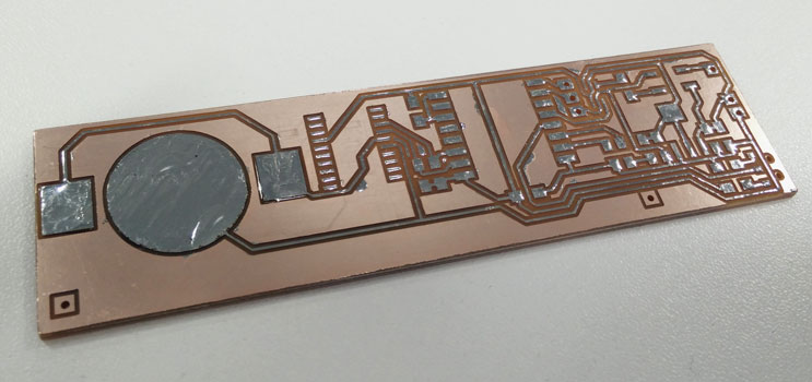
Since I want this board to last, I washed it in soapy water and tinned all the traces.
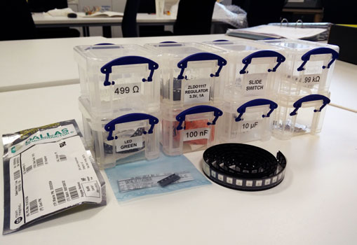
After that I gathered all the necessary components and stuffed the board. I did have one small misshap during the stuffing. I accidentally soldered the voltage shifter off-by-one and let the magic smoke out when I applied power. Woops!
Hello World Testing
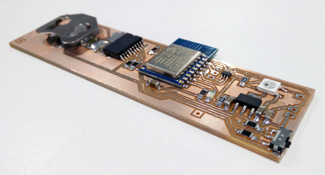
Using the Arduino IDE for the ESP8266, I set up a quick rainbow LED sketch as a "Hello World!" test.
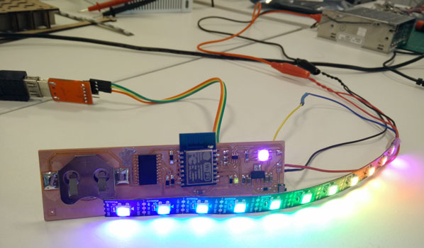
Success! Running everything on one microcontroller should really easy development (and BOM cost). I knew I was going to have to make another PCB as my mounting holes for this one were pretty pathetic, but it did mean I had a small prototype I could carry about in my bag.
Basic electronics hardware done, I moved onto Laser Cutting and Mechanical Improvements.
Comments
comments powered by Disqus