This week's assignment was very interesting and was about applying what we have learnt so far. For this assignment we had to make a pcb which had any one of the sensors (to take an input) from the list of sensors given.
I was really fascinated by the magnet sensor board and decided to make a board which would sense magnetic fields.
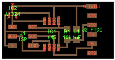
The board layout (http://academy.cba.mit.edu/classes/input_devices/mag/hello.mag.45.png) and the png file (http://academy.cba.mit.edu/classes/input_devices/mag/hello.mag.45.traces.png) were available on the input devices assignment page.
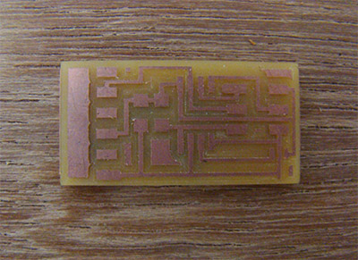
After completing the board layout I converted the PNG to .rml file for the ROLAND MODELLA machine to mill the pcb.
All the components were easily available in the CEPT Fablab. Going by the practice I made a list of the components required and stuck them to the sheet. Then soldering was the next step. I 've realized that my speed of soldering has greatly improved!
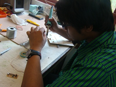
After milling two PCB at a time, reference from http://academy.cba.mit.edu/content/tutorials/akf/electronics_production_FabISP.html helped a lot. Sequence of soldering is very important. Minute details like orientation of component certainly matters for circuit to work. All placed well. All the above process took 8 odd hours.
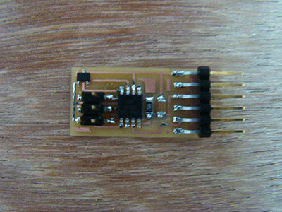
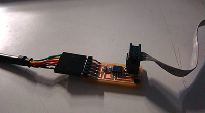
I got a green light in the AVRISP in the first go and hence it was now ready to be programmed
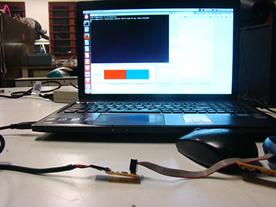
The programming was done in Ubuntu according to the tutorial by making changes to the makfile. The C code was flashed successfully.
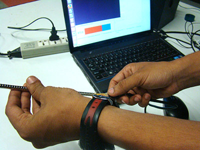
The visualization was done in Python. After installing pyserial on my system, the visualization was done and it worked perfectly!