week 2: computer-controlled cutting
Experiments on light fixtures is one of the many interests of mine . For this asssignment, we (Mysself and Ankita Diwan), tried to make a quick test of press fit construction technique to make lamp. This was only 6 hours job including revision of file with respect to change in material thickness. We learnt that this is a very quick method to "make" interesting three dimensional geometry using 2D cutting.
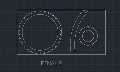
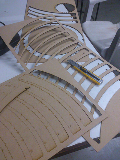
To begin with, we fixed the outer dimensions of the lamp. An inscribed geometry of 300 x 300 x 300mm. We wanted lamp to have circular/arc shapes. Based on that we fixed two circular rings one for the top and the other at the bottom to hold all vertical members. Bottom ring outer diameter be 300mm and width of the strip to be 25mm. Similarly top ring outer diameter be 125mm and width of strip to be 25mm. Then we drew the exact shape of the vertical members. again the width of this strip is 25mm. In the next step we fix the number of vertical members. Initally we drew 40. That was too much. In that case the distance between to members was too close. So we started reducing the numbers by 10 and made 30. This was good number. After this is the joinary. Initially we decided to make this is cardboard 4mm thick. So all the joints were made 4 x 8mm straight. We tested on a small carboard sheet and realised of we use 'clip joint' it should work better. So joints were revised as 4 x 8 x 5mm so this created a wedge of 1mm. But this was enough for the spring effect. To make sorresponding joint on the vertical member, we chose to fix top ring 25mm below with reference to the top of vertical member and bottom ring 25mm above bottom of vertical member.
Due to some problems with cardboard availability, we had to shift on 2mm MDF. Therefore, all the joints details had to be revised as per 2mm thickness.

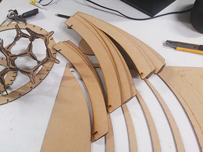
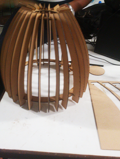
Lamp Assembled.