week 17 final project (dynamic 'jali')
After long hours of preparation, we finally have been able to produce a working prototype of what we intend the final model to be. While I made all the initial prototypes and the final one with the rivets, Ashris and Ankita helped documenting the entire process.
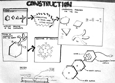
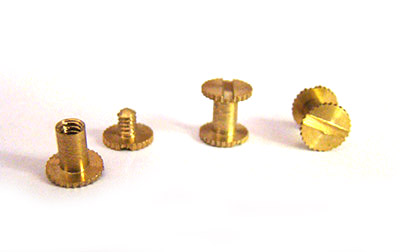
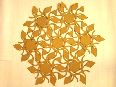 First protoype I made was using paper (mill board), cut using laser machine and fixed with revets manually. The height of revets was too high so while fixing them for just two sheets of paper put together, only 1mm thickness, it was too. Extra metal flattened at the back restricted movement. This one was almost fixed prototype. No modules moved.
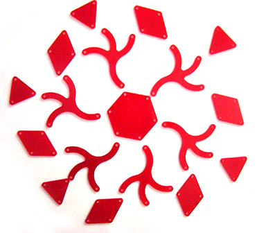
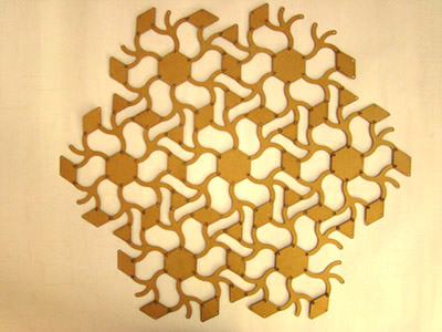 In the next attempt, I scaled up modules with respect to the correct size and height of revet used. Again the modules were cut in paper using laser cutter.
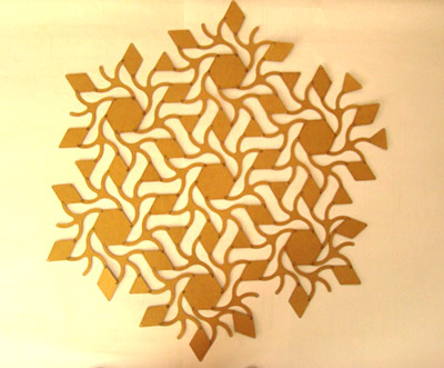
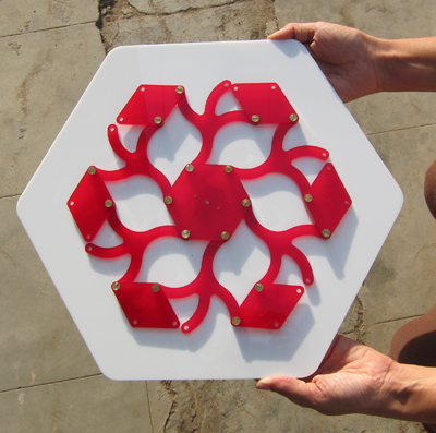
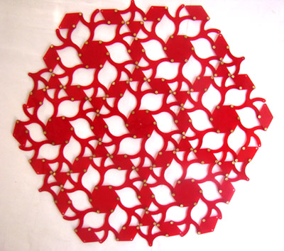
Fourth prototype was then made using PVC sheet. Laser cutting burnt the edges of this but for testing material, it was OK. This time thickness (1.5mm) of material was also chosen carefully and with respect to the same size of revets. This was first successful prototype with respect to the smoothness of motion. However, because the edge components (Rhombus) kept keep getting stuck in the extreme open and closed positions. Due to this in case of forceful motion, connection menmers broke. Therefore, next improvement in the prototype to be made was boundary conditions, edge connections and better fixing then revets.
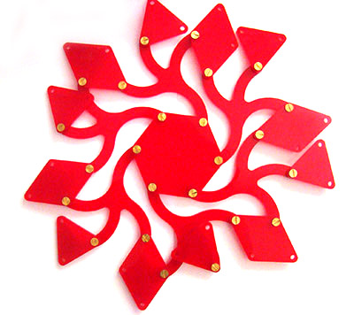
First movement (Completely closed).
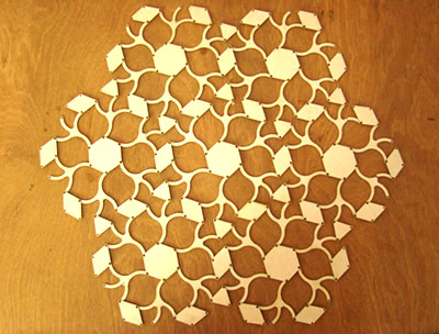
Second movement/Central position (Completely open)
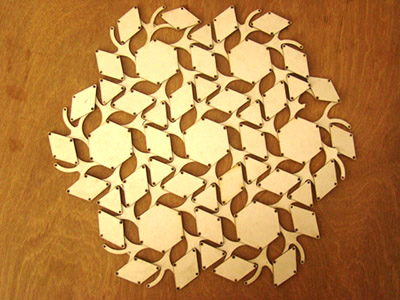
Third movement (Completely closed) again
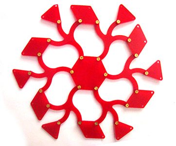
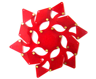
Seven modules connected together.
Final tile in First movement
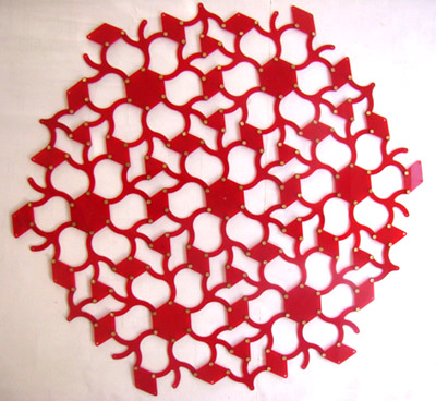
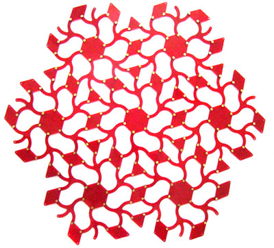
Second movement (Open position)
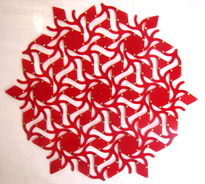
Third movement. After this protoypes were ready, electronics trials began.
To begin with we researched on how to make own circuit. Also tried to twik input devices assignment of FabAcademy to manipulate sound input. Found research paper on similar project but the circuit didnt work following the theoritical explantion using microcontroller and servo motor. Due to limited time after all the tiy outs, I took help of experts (PlayLab) to make it work. Finally it worked with an Arduino board and DC motor.
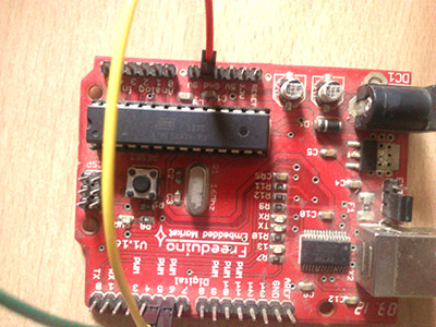
Hardware: Arduino Duemilanove (Freeduino);
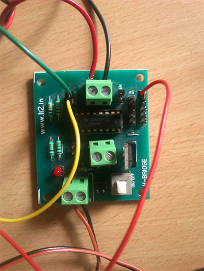
L293D Motor Driver (H-bridge PCB);
150 RPM, 12 V DC Motor.
Software: Arduino IDE 1.0.5.
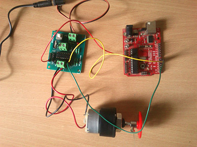
Circuit diagram:
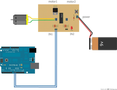
Connection: First connect the red wire from the GND pin of Arduino (red board) to GND pin on the H-bridge PCB (green board). Next connect green wire from 5 of Arduino to any one pin of IN2 on the H-bridge. Next connect yellow wire from 6 of Arduino to the other pin of IN2 on the H-bridge. Connect the motor wires to the screw terminal besides IN2. Polarity won't matter. Next just connect the Arduino board to the computer via the USB cable. It should blink some lights on the board. Don't worry if drivers aren't installed, we just need the power from the computer. Finally connect the power jack to the Adapter and switch it on.
Code:
//normal forward-backward motion of motor with delay
void setup()
{
pinMode(5,OUTPUT);
pinMode(6,OUTPUT);
}
void loop()
{
analogWrite(5,150);
analogWrite(6,0);
delay(200);
analogWrite(5,0);
analogWrite(6,150);
delay(200);
}
Working of the final module with the whole assembly. The above assembly and electronics is only capable of moving one module. Till now this is the resolution achieved on electronics side. To make the movement absolutely smooth and house the electronics components, an acrylic box is made.