Week 4: Electronics Production
Goal: make the FabISP in-circuit programmer
This assignment has two steps, first to make the board and the second one to program the board.
Step 1: Making the board
As reference files I used the files provided in the week 4 class for milling and program the board.
board:
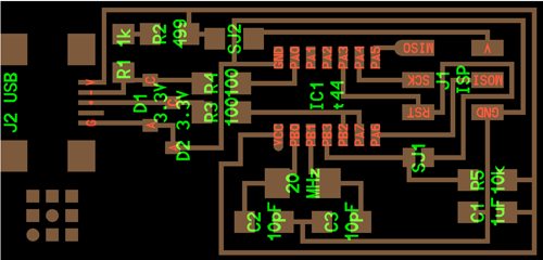
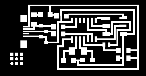
traces:
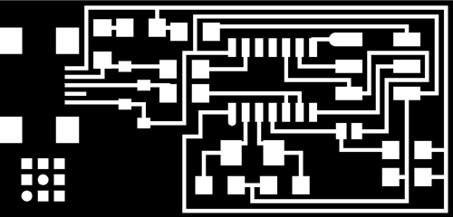
|
|
For milling the board, I use the Roland Modela with a diamond drill 0.6 mm in diameter.
I use Roland's software for engraving and cutting plate, Dr.Engrave. The problem I have is the software does not calibrate well the cutter diameter with paths, so you need to pay close attention because in the places where the black surface is less than the diameter of the cutter the software don't drill the board, so before machining we have to review the file to correct the errors and have a correct machining paths otherwise the paths will be in contact with others in the points where they have not been cut.
|
The main problem with the Dr.Engrave software is the offset of the first path is not accurate and makes smaller the circuit connections, sometimes even eliminatethem and avoid the conductivity between parts of circuit. Here are some examples of boards where I had these problems.
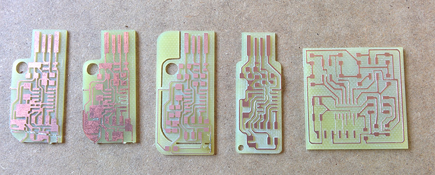
To fix that, I have done is to make wider paths using Photoshop, so I make sure that there will be connected the dots. Not a great solution but it is effective. In the future I'll try to use FabModules, but working on the windows, Dr.Engrave was the fastest option.
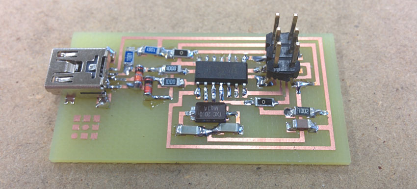
Now I drill de board and weld the components.
I have already made the FabISP, now I have to program it. When I connect it to the computer, this recognizes it as an "Unknown Device", this is correct because the FabISPis not yet programmed.
Step 2: programming the board
This step has been especially difficult for me because I found a lot of problems that took several weeks to resolve and I have delayed the others assignments with circuits .
My first problem is that we are a new FabLab that opened this year and we don't have a previous FabISP which program with and did not have any other programmer . We tried to enter the code using Arduino as ISP but it is not possible because the Bootloader Arsuino IDE is not c code.
Finalment we got a AVRISP v2 programmer and I started programming my FabISP it by following this tutorial. I installed AVR DUDE to enter the code on the board and downloaded the Firmware and Drivers for my computer to recognize the FabISP .
As I do not use one FabISP as a programmer , but a AVRISP2 , at the beginning is not necessary to install the drivers for the FabISP, but I'll have to install the AVRISP2 drivers for the computer recognizes it and can use it as a programmer . Once I have programmed my FabISP, then I should install the FabISP drivers for the computer recognize the board.
Now connect the computer to the AVRISP2 with an USB and my FabISP also in order it can get energy. Both boards must be connected by a 3x2 pins wire.
I open the windows console to start programming . If I want to check that AVRDUDE is properly installed I write in the console "AVRDUDE" and I appear all the available commands. Now I go into the folder where I downloaded the firmware and I can start.
First type:
and show:
c:\Users\FabLab/Desktop/firmware>make clean
rm -f main.hex main.lst main.obj main.cof main.list main.map main.eep.hex
main.elf *.o usbdrv/*.o main.s usbdrv/oddebug.s usbdrv/usbdrv.s |
after that type:
and show:
c:\Users\FabLab/Desktop/firmware>make hex
avr-gcc -Wall -Os -DF_CPU=20000000	 -Iusbdrv -I. -DDEBUG_LEVEL=0
-mmcu=attiny44 -c usbdrv/usbdrv.c -o usbdrv/usbdrv.o
avr-gcc -Wall -Os -DF_CPU=20000000	 -Iusbdrv -I. -DDEBUG_LEVEL=0
-mmcu=attiny44 -x assembler-with-cpp -c usbdrv/usbdrvasm.S -o usbdrv/usbdrvasm.o
avr-gcc -Wall -Os -DF_CPU=20000000	 -Iusbdrv -I. -DDEBUG_LEVEL=0
-mmcu=attiny44 -c usbdrv/oddebug.c -o usbdrv/oddebug.o
avr-gcc -Wall -Os -DF_CPU=20000000	 -Iusbdrv -I. -DDEBUG_LEVEL=0
-mmcu=attiny44 -c main.c -o main.o
avr-gcc -Wall -Os -DF_CPU=20000000	 -Iusbdrv -I. -DDEBUG_LEVEL=0
-mmcu=attiny44 -o main.elf usbdrv/usbdrv.o usbdrv/usbdrvasm.o usbdrv/oddebug.o
main.o
rm -f main.hex main.eep.hex
avr-objcopy -j .text -j .data -O ihex main.elf main.hex
avr-size main.hex
text	   data	    bss	    dec	 hex	filename
0 2050 0 2050 802 main.hex |
And then:
problem: although the crystal is 20 MHz, the programming must be at a frequency of 1/4 of the crystal, at first I was programming with the programmer working at 20 Mhz and had an error in the Fuse. Finally I got into the drivers of the programming and I reduced to 5 Mhz. After that, everything worked correctly when I made the Fuse:
c:\Users\FabLab/Desktop/firmware>make fuse
avrdude -c avrisp2 -p attiny44  -U hfuse:w:0xDF:m -U lfuse:w:0xFF:m

avrdude: AVR device initialized and ready to accept instructions

Reading | ################################################## | 100% 0.01s

avrdude: Device signature = 0x1e9207  avrdude: reading input file "0xDF"
avrdude: writing hfuse (1 bytes):

Writing | ################################################## | 100% 0.00s

avrdude: 1 bytes of hfuse written  avrdude: verifying hfuse memory against 0xDF:
avrdude: load data hfuse data from input file 0xDF:
avrdude: input file 0xDF contains 1 bytes  avrdude: reading on-chip hfuse data:

Reading | ################################################## | 100% 0.00s

avrdude: verifying ...  avrdude: 1 bytes of hfuse verified
avrdude: reading input file "0xFF"  avrdude: writing lfuse (1 bytes):

Writing | ################################################## | 100% 0.01s

avrdude: 1 bytes of lfuse written  avrdude: verifying lfuse memory against 0xFF:
avrdude: load data lfuse data from input file 0xFF:
avrdude: input file 0xFF contains 1 bytes
avrdude: reading on-chip lfuse data:

Reading | ################################################## | 100% 0.00s

avrdude: verifying ...  avrdude: 1 bytes of lfuse verified
avrdude: safemode: Fuses OK

avrdude done. Thank you. |
finally, the problems appear:
and:
c:\Users\FabLab/Desktop/firmware >make program
avrdude -c avrisp2 -P COM5 -p attiny44 -U flash:w:main.hex:i
avrdude: stk500v2_command(): command failed
avrdude: stk500v2_command(): unknown status 0xc9
avrdude: stk500v2_program_enable(): cannot get connection status
avrdude: initialization failed, rc=-1
Double check connections and try again, or use -F to override this check.
avrdude done. Thank you.
make: *** [flash] Error 1
|
After verifying the connections are good and that there is continuity in the circuit, I install ATMEL STUDIO to verify the board.
Connecting the FabISP, Atmel Studio is able to recognize the microcontroller I am using an ATtiny 44, but is unable to identify the other components (or the crystal), so surely there is a problem with any of them.
After reviewing everything thoroughly, I found the capacitators placed close crystal are not the value they should be, they are 100pF instead of 10pF. Unweld the wrong capacitators and weld the right ones. Atmel Studio now recognizes the components of the board.
I get back to the console windows and Firmware folder and repeat the last operation:
finally:
and...
c:\Users\FabLab/Desktop/firmware >make program
avrdude -c avrisp2 -P COM5 -p attiny44 -U flash:w:main.hex:i
avrdude: AVR device initialized and ready to accept instructions

Reading | ################################################## | 100% 0.01s

avrdude: Device signature = 0x1e9207
avrdude: NOTE: FLASH memory has been specified, an erase cycle will be performed
To disable this feature, specify the -D option.
avrdude: erasing chip
avrdude: reading input file "main.hex"
avrdude: writing flash (2020 bytes):

Writing | ################################################## | 100% 5.68s


avrdude: 2020 bytes of flash written
avrdude: verifying flash memory against main.hex:
avrdude: load data flash data from input file main.hex:
avrdude: input file main.hex contains 2020 bytes
avrdude: reading on-chip flash data:

Reading | ################################################## | 100% 3.36s


avrdude: verifying ...
avrdude: 2020 bytes of flash verified

avrdude: safemode: Fuses OK

avrdude done.  Thank you.

avrdude -c usbtiny -p attiny44  -U hfuse:w:0xDF:m -U lfuse:w:0xFF:m

avrdude: AVR device initialized and ready to accept instructions

Reading | ################################################## | 100% 0.01s


avrdude: Device signature = 0x1e9207
avrdude: reading input file "0xDF"
avrdude: writing hfuse (1 bytes):

Writing | ################################################## | 100% 0.00s


avrdude: 1 bytes of hfuse written
avrdude: verifying hfuse memory against 0xDF:
avrdude: load data hfuse data from input file 0xDF:
avrdude: input file 0xDF contains 1 bytes
avrdude: reading on-chip hfuse data:

Reading | ################################################## | 100% 0.00s


avrdude: verifying ...
avrdude: 1 bytes of hfuse verified
avrdude: reading input file "0xFF"
avrdude: writing lfuse (1 bytes):

Writing | ################################################## | 100% 0.00s


avrdude: 1 bytes of lfuse written
avrdude: verifying lfuse memory against 0xFF:
avrdude: load data lfuse data from input file 0xFF:
avrdude: input file 0xFF contains 1 bytes
avrdude: reading on-chip lfuse data:

Reading | ################################################## | 100% 0.00s


avrdude: verifying ...
avrdude: 1 bytes of lfuse verified

avrdude: safemode: Fuses OK

avrdude done.  Thank you.
|
Now I have the FabISP working!!! |


