I chose the light sensor for these assignment because I want to use this to detect the puck pass through the goal in my air hockey table (the original final project)
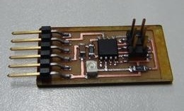
Manufacturing de Circuit
For this part I used the technics of the Electronic Production Assignment.
All the files you need to manufacture the board with light sensor (phototransistor) are in Fab Academy's web.
Programming the Hello Light
For this part I did in diferent way than the last programming assignment, when I used the ATMEL Studio 6. Now I did it with de WinAVR in Windows 7 - 64bits OS.
Getting the Programs & Files
You will need for this part:
Place it on the Desktop, or where you want.
Creating the Makefile
Open the MFile[WinAVR] program. This program help you to create the Makefile to program your microcontroller.
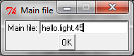
Step 01.- Write the name of the program file, go to > in the new window that will appear write hello.light.45 (the file extension .c has to be omitted)
Step 02.- Start the configuration selecting the microcontroller:
> > >
Step 03.- Select the programmer:
> >
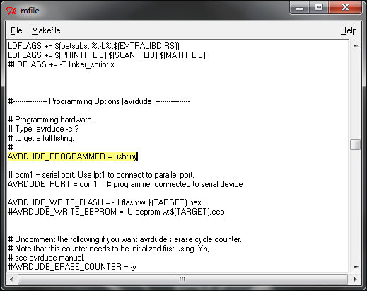
If you don't find you will need to modify manually the file. First allow introduction of text in the makefile:
>
Then find the line with AVRDUDE_PROGRAMMER, and type:
AVRDUDE_PROGRAMMER = usbtiny
Step 04.- Then select the port of the FabISP, go to > > .
Step 05.- > and save the makefile (put in the same folder where you downloaded the hello.light.45.c file).a
Programming the ATtiny45
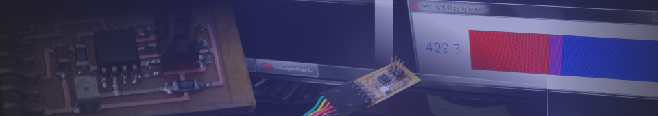
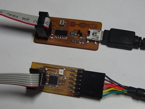
Step 01.- Connect the FabISP and the Light Sensor Board like the picture. Verify that the devices was recogniced (go to Start Menu > Devices and Printer). Check if the FabISP and/or the USB-Serial Adapter don't have problems (driver problems), otherwise install the drivers (the windows normally install the USB-Serial Asapter drivers)
Step 02.- Open the Programmers Notepad[WinAVR] and create a new project write the name of your proyect in the |
 |
Step 03.- In the explorer bar right click on the proyect icon and choose . Find the hello.light.45.c file and add it, do the same with the makefile |
 |
Step 03.- Proceed to compile the files, go to > . If all is correct, the following text will appear in the Output Window (at the bottom of the Programmer's window).
> "make.exe" all

-------- begin --------
avr-gcc (WinAVR 20100110) 4.3.3
Copyright (C) 2008 Free Software Foundation, Inc.
This is free software; see the source for copying conditions.  There is NO
warranty; not even for MERCHANTABILITY or FITNESS FOR A PARTICULAR PURPOSE.


Compiling C: hello.light.45.c
avr-gcc -c -mmcu=attiny45 -I. -gdwarf-2 -DF_CPU=8000000UL -Os
-funsigned-char -funsigned-bitfields -fpack-struct -fshort-enums -Wall
-Wstrict-prototypes -Wa,-adhlns=./hello.light.45.lst  -std=gnu99 -MMD -MP
-MF .dep/hello.light.45.o.d hello.light.45.c -o hello.light.45.o

Linking: hello.light.45.elf
avr-gcc -mmcu=attiny45 -I. -gdwarf-2 -DF_CPU=8000000UL -Os -funsigned-char
 -funsigned-bitfields -fpack-struct -fshort-enums -Wall -Wstrict-prototypes
 -Wa,-adhlns=hello.light.45.o  -std=gnu99 -MMD -MP -MF
 .dep/hello.light.45.elf.d hello.light.45.o --output hello.light.45.elf
 -Wl,-Map=hello.light.45.map,--cref     -lm

Creating load file for Flash: hello.light.45.hex
avr-objcopy -O ihex -R .eeprom -R .fuse -R .lock hello.light.45.elf
 hello.light.45.hex

Creating load file for EEPROM: hello.light.45.eep
avr-objcopy -j .eeprom --set-section-flags=.eeprom="alloc,load" \
	--change-section-lma .eeprom=0 --no-change-warnings -O ihex
     hello.light.45.elf hello.light.45.eep || exit 0

Creating Extended Listing: hello.light.45.lss
avr-objdump -h -S -z hello.light.45.elf > hello.light.45.lss

Creating Symbol Table: hello.light.45.sym
avr-nm -n hello.light.45.elf > hello.light.45.sym

Size after:
AVR Memory Usage
----------------
Device: attiny45

Program:     420 bytes (10.3% Full)
(.text + .data + .bootloader)

Data:          0 bytes (0.0% Full)
(.data + .bss + .noinit)

-------- end --------


> Process Exit Code: 0
> Time Taken: 00:01
Step 04.- Proceed to program your microcontroller, go to > . If all is correct, the following text will appear in the Output Window.
> "make.exe" program
avrdude -p attiny45 -P usb -c usbtiny    -U flash:w:hello.light.45.hex

avrdude: AVR device initialized and ready to accept instructions

Reading | ################################################## | 100% 0.01s

avrdude: Device signature = 0x1e9206
avrdude: NOTE: FLASH memory has been specified, an erase cycle will be
performed
         To disable this feature, specify the -D option.
avrdude: erasing chip
avrdude: reading input file "hello.light.45.hex"
avrdude: input file hello.light.45.hex auto detected as Intel Hex
avrdude: writing flash (420 bytes):

Writing | ################################################## | 100% 0.63s

avrdude: 420 bytes of flash written
avrdude: verifying flash memory against hello.light.45.hex:
avrdude: load data flash data from input file hello.light.45.hex:
avrdude: input file hello.light.45.hex auto detected as Intel Hex
avrdude: input file hello.light.45.hex contains 420 bytes
avrdude: reading on-chip flash data:

Reading | ################################################## | 100% 0.29s

avrdude: verifying ...
avrdude: 420 bytes of flash verified

avrdude done.  Thank you.

> Process Exit Code: 0
> Time Taken: 00:02
Step 05.- The Light Sensor Board is programmed, now you can disconnect your FabISP.
Using the Python Interfase
For this part I follow the Input Devices Tutorial from AS220 Fab Lab. I used Python for the Windows, I didn't have any troubles this tutorial.
Testing
Now is time to test the sensor with my desktop lamp.

Exposed to direct light - 575.0 value |

Making Shadow with my finger - 1006.6 Value |
Also I made a video, using Ubunto OS, and a flashlight.