The mechanism
The original idea was to create the table where my Air Hockey table will be placed, but I think is too simple, so I think in a mechanism to made the board move up and down.
The Design
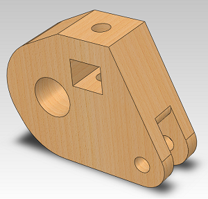
The 3D-CAD design I did in SW.
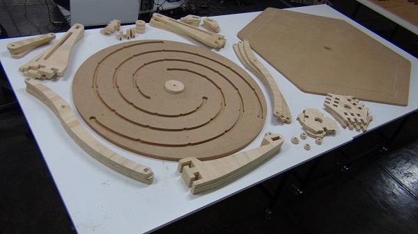
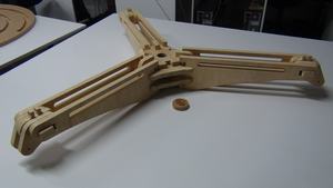
This table base consist in 3 arms with a rail inside and a small car over the rail. 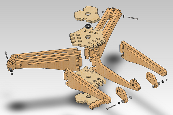
The movement of this car action the mechanism that fold and unfold the leg.
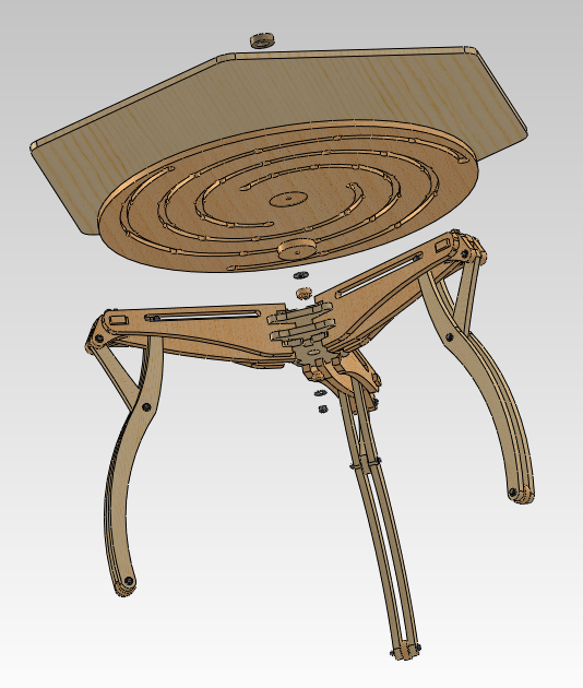
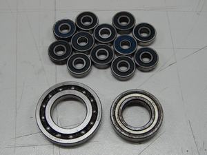
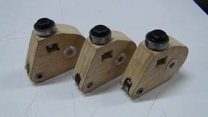
Each car(3) has a bearing in the top that couple with the the spiral canal (show in the picture), so when the table (or the leg) turn the car move and the leg fold or unfold.
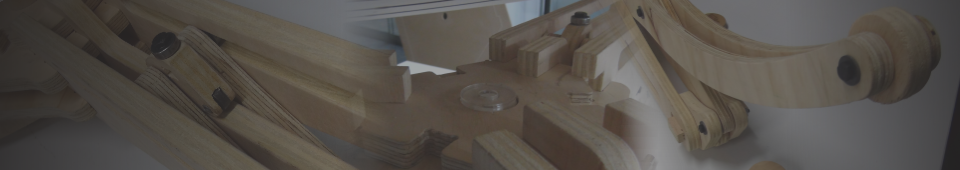
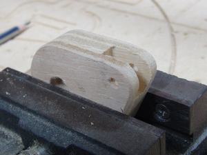
The car part geometry, was the more complicated to mill, it needs milling in many faces of the piece. The milling process was special for these part.
The design used 18mm (download files) and 20mm (download files) plywood boards.
The Fabrication
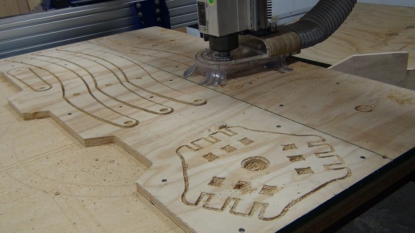
For the fabrication, the machining, I always prefere to use the wastepieces of other works (reuse) that normally ends in the trash.
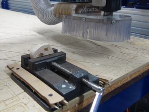
The car connected to the legs and the spiral under the table was the most complicated The car connected to the legs and the spiral under the table was the most complicated part that these machine need. To manufacture this I need to fix a vice to the milling table and made some milling throw the sides. The top face needs a hole, the laterals was milled like traditional routing, and the bottom face (or front face) needs a canal, so each side needs to be fixed with the vice, then calibrated the origin and then milled.
I used the ¼" flat end mill. The parameter for a fast cut are:
- Pass Depth = ¼" (you can use ½" if you want a faster cut but the border has a worst finish)
- Cut Speed (movement) = 4 - 5 inch/sec.
- Spindle speed = 12000rpm.
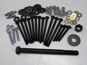
Parts
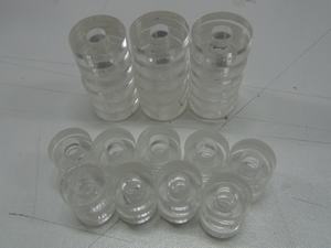
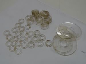
All the wood parts of the leg and the center parts are cutted from 18mm plywood, the arms are from 20mm plywood, only the top table (hexagonal) and the big circle (w/ the spiral) are from 18mm MDF. Also I used acrylic bushings/washers and for rotating parts...As resume:
 |
 |
 |
 |
Construction
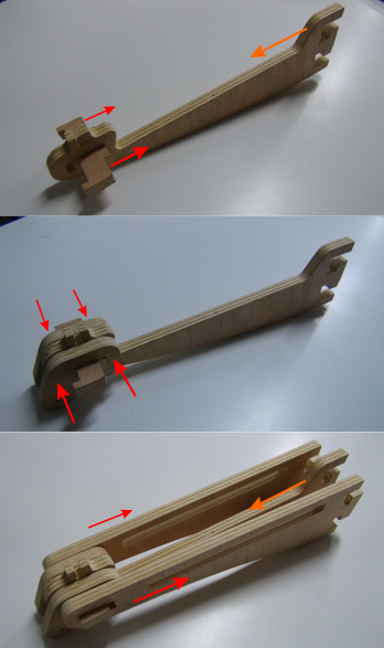 |
← First assembly the arm. All the parts are constructed with lose fit (it don't use press-fit), but the pieces lock together; so is important to follow the arrows for the assembly 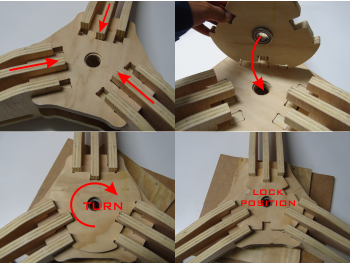
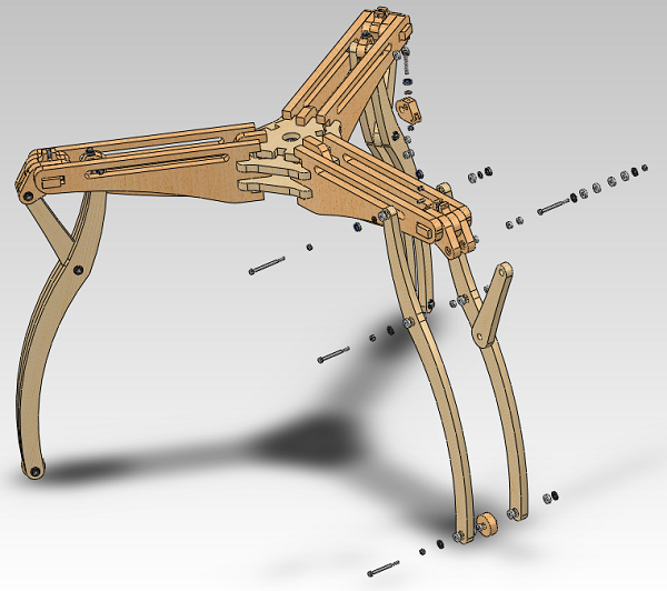
↑ Then connect the three arms with the the center parts. Two on top and two on bottom, the external board is a lock. At the end you will obtain this ↓ |
The picture below show all the other parts from the construction of the base. 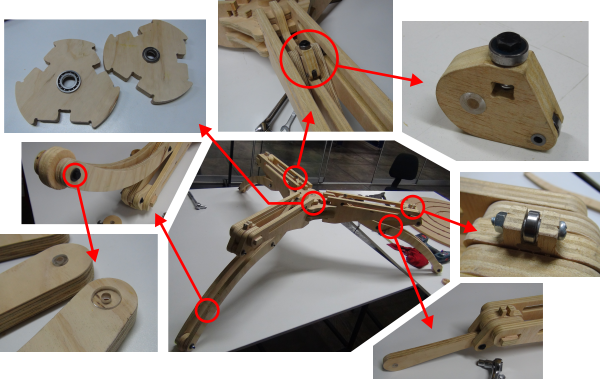
The picture below show the table completly assembled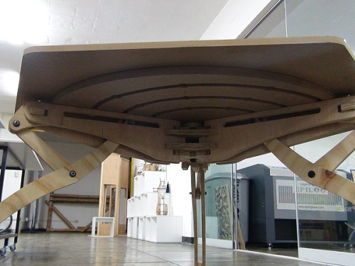
Testing
Now is time to test the mechanism. Only turning the legs or the table (depends which is fixed) the legs retracts or extends, allowing the table grow up or down.

Lowest Position |
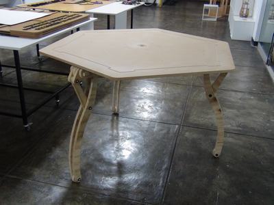
Highest Position |