Electronics Design
While the focus of the Electronics Production unit was on taking a given circuit design and learning how to make it, this week was about learning the tools to design your own circuits from scratch. This involved learning EAGLE, software that allows you to lay out your circuit design, and automatically turn that schematic into a PCB layout that can be sent to a mill.
The Schematic
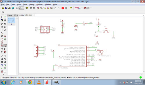
Beginning with the "Hello Echo" design given to us in our FabLab library, I layed out the additional components necessary to create a simple circuit containing a LED that can be turned on/off with a button:
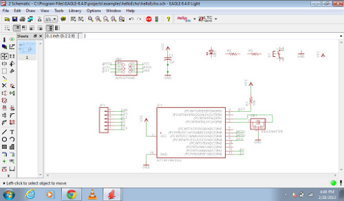
Now the electrical components had to be connected, both to each other, as well as to the microcontroller. The EAGLE interface was quite intuitive. The only issue was that sometimes the wires were not actually connected; adding junctions seemed to fix this easily.
 he
he
The Board View
The resulting board layout:
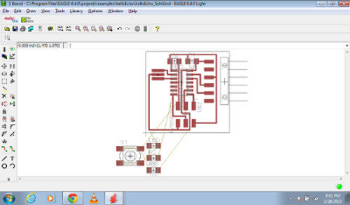
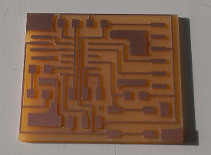
It took a little playing around with the board layout to get something that could be properly milled, but once done, it was simple to export the file to a .png:
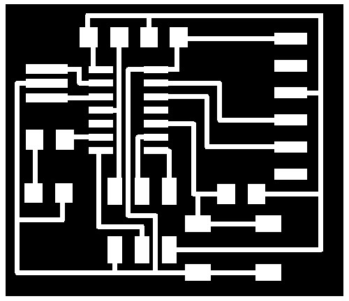
From here, it was a repeat of Electronics Production week, and simply involved milling and stuffing the board:
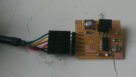
I still have to program the microcontroller, but my computer seems to recognize the device!
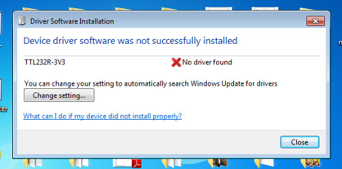
Hopefully all will go smoothly...I'll update this once I see for sure.

