Fab Labs. Advanced made simple.
Local Solutions for local problems.
Posted by James Akumu | For Fab Academy
Input Devices Project
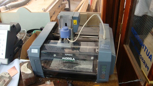
For this project, we are to program an input device on a microcontroller board, using the Roland Modela, a PCB design program and an in-system programmer.
I decided to make the hello phototransistor first, and then make the hello microphone next. I started with Eagle, to design the board. I added all the necessary components to the schematic, and netted them.
After all the components were netted, I routed the traces on the board.
I then removed all the components, to leave behind only the traces and pads. The design is now ready for export.
I did some editing in Gimp. I added some text, flattened the image, and reduced the canvas size. The PCB design is now ready to be milled.
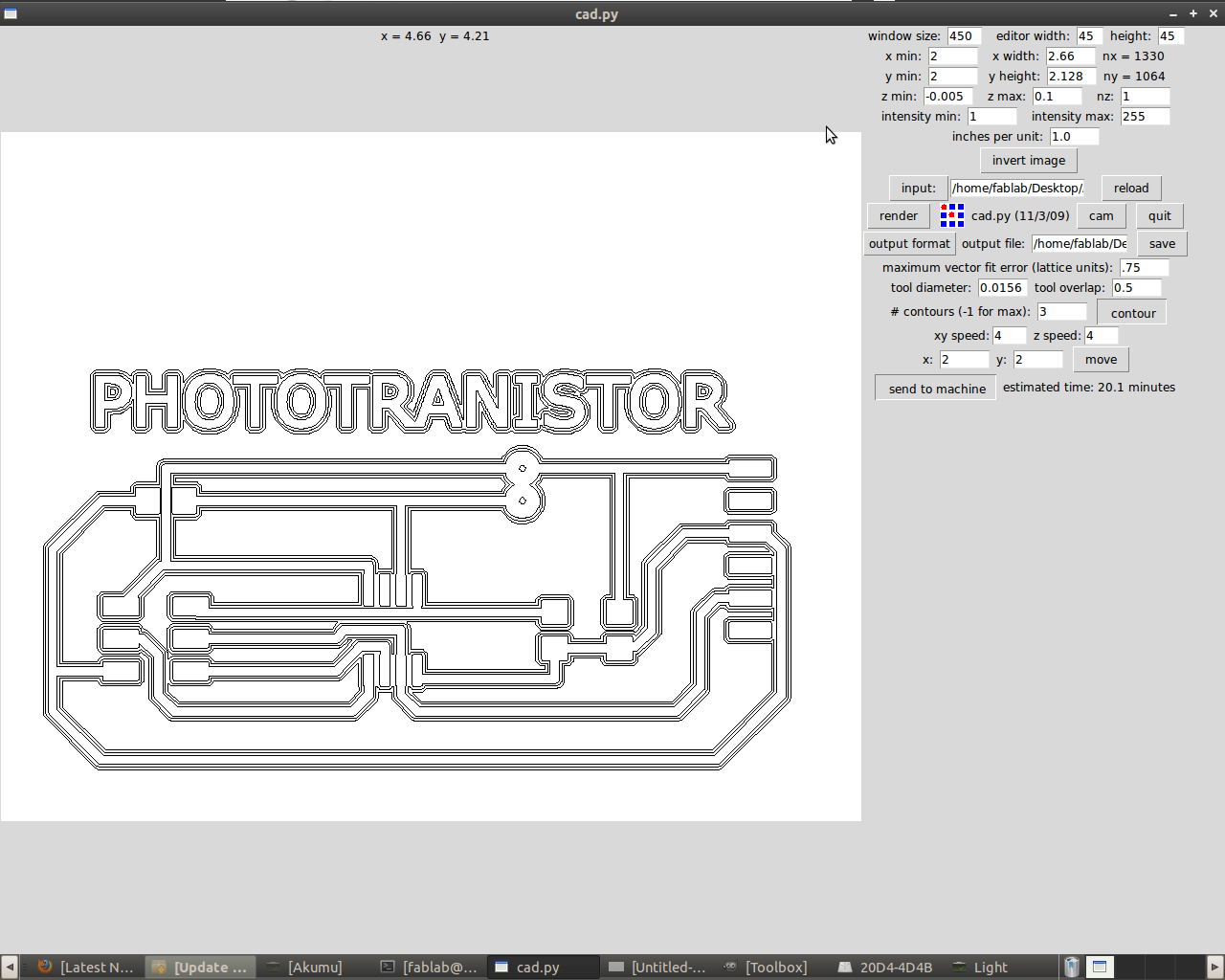
This first board was milled with the contour value at 3. Many traces got milled off. I have marked the problem areas with red circles. I will try again with a higher contour value.
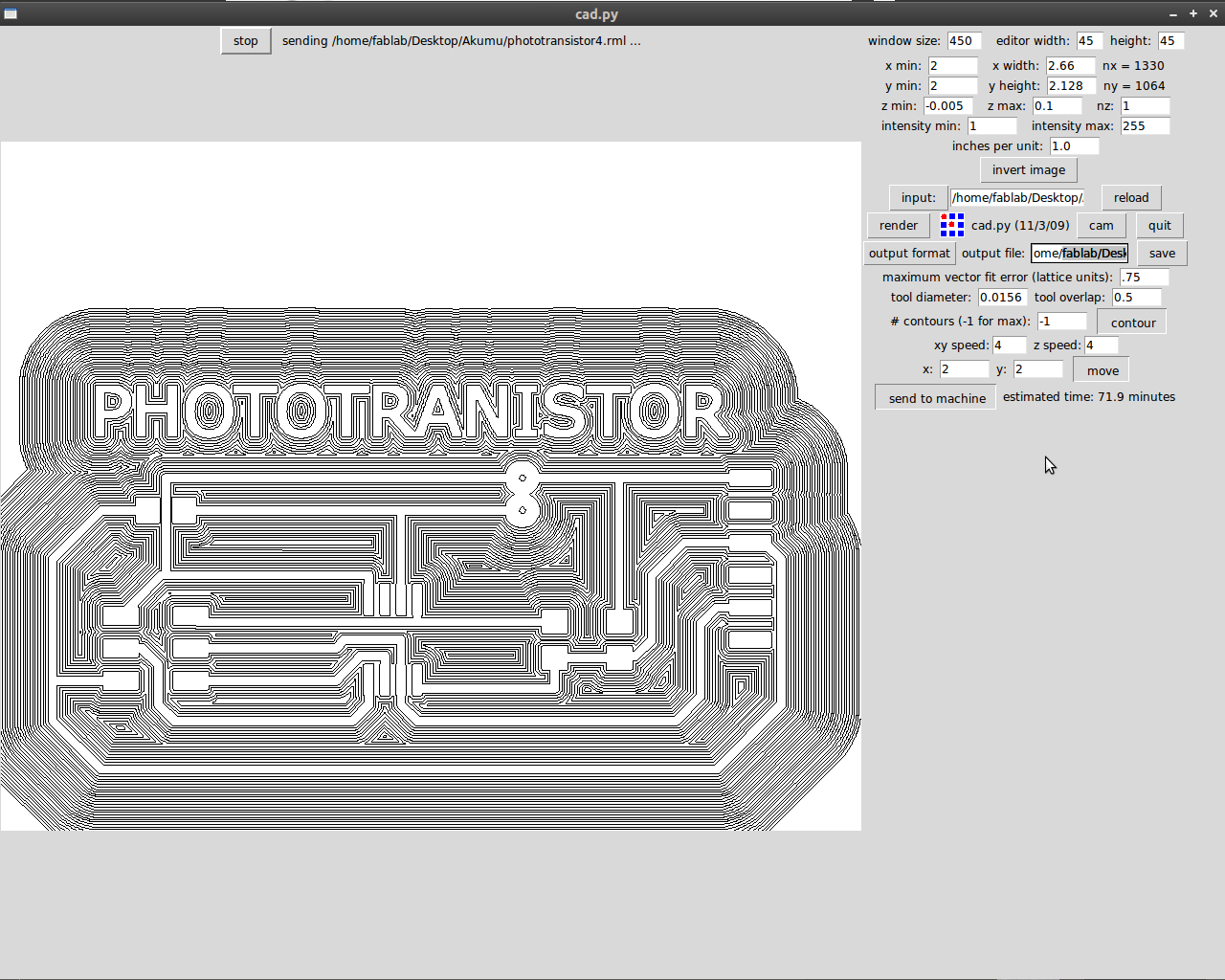
For the second board, I used the maximum contour value of -1. Unfortunately the same problem arose. I will try again.
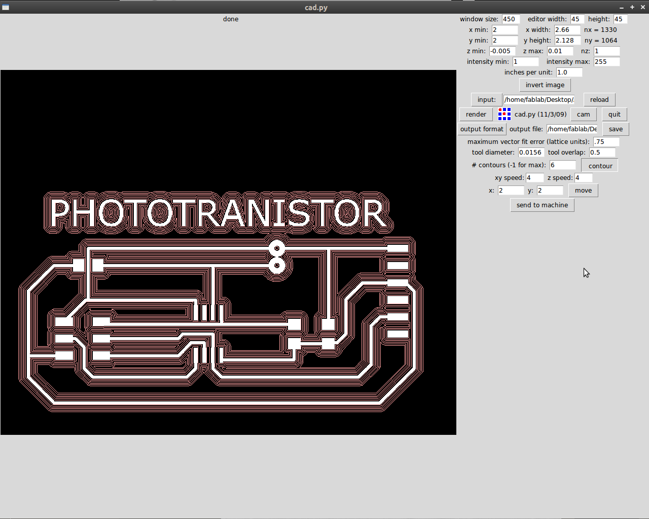
For the third board, I used a contour value of 6. The very same traces were milled off again. I have been advised to go back to Eagle, and make my traces thicker. I will do that before milling another board.