Final Project
![]()
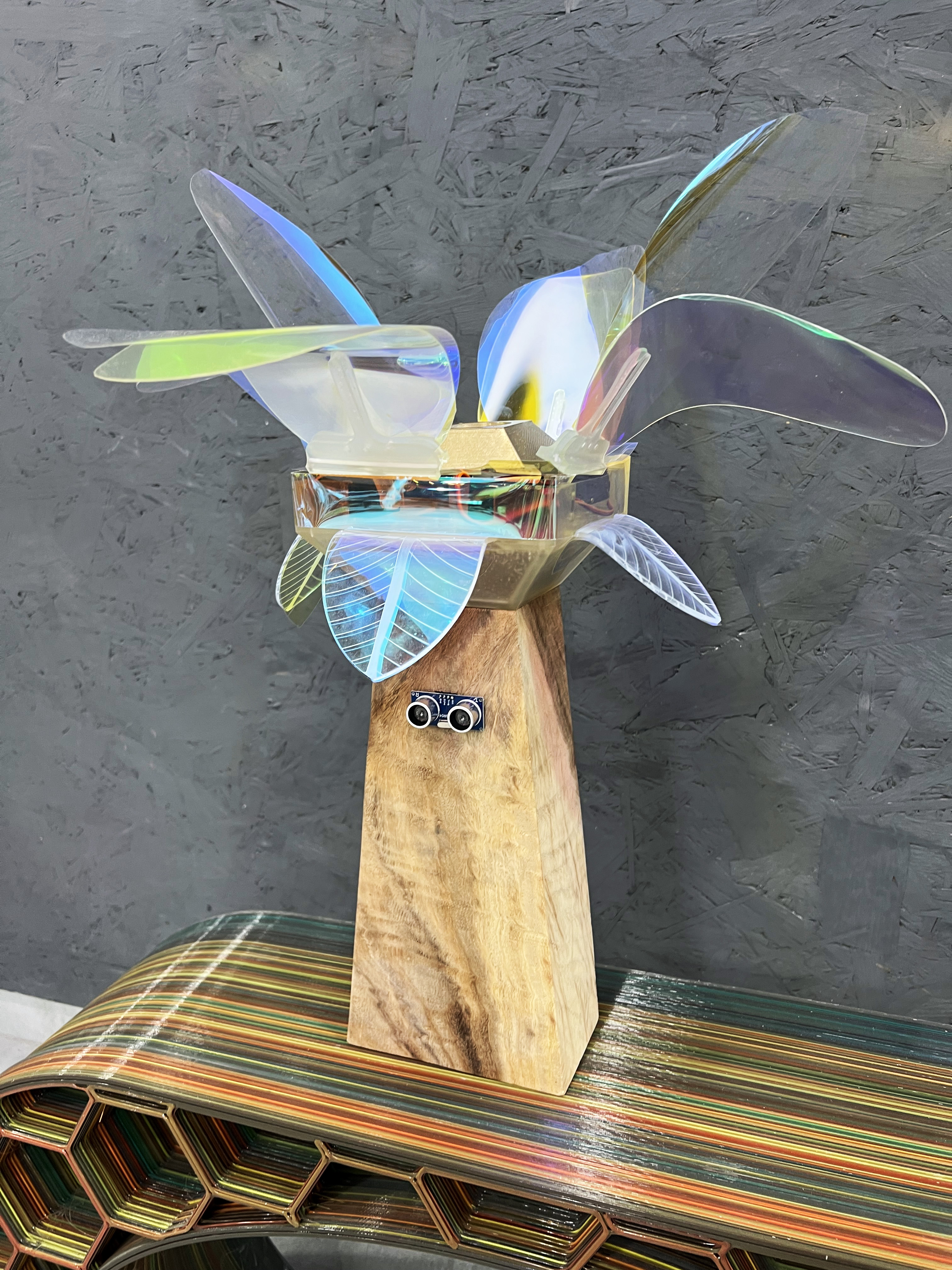
mechanical flower Art installation
My purpose is to build a state of the art mechanical flower that interacts with passersby through the HC-SR04 Ultrasonic sensor that will ditect distance, once people come closer than 50cm the flower will open up.
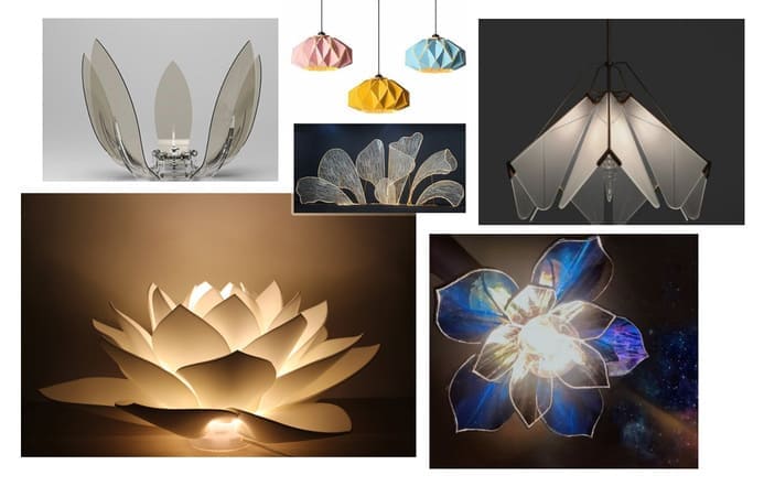
Similar projects have been done before, here are some of my inspirations.
This project from a previous group project in waag fab lab
What did I design?
The Physical Components: 1- The wooden block (where the motion sensor is attached) 2- The cone (home for my motors and PCB) 3- The petals (moving and fixed) 4- The shaft that will transfer motion from motor to petals.
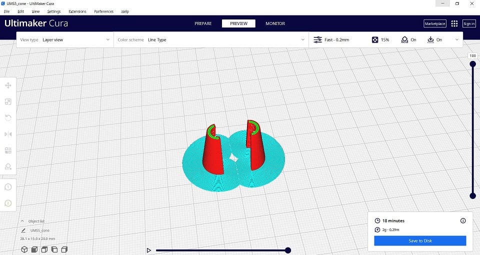
The Cone was 3d printed with clear resin.
For Design Integration I got all my components ready, my motors will be placed on top of the cone, PCB will be placed inside the cone where all the wires will be connected from motors-PCB-to wooden block where I placed my sensor and where power source is located too.
That was all part of the plan, I’ll explain later in this page how some parts didn’t come together as planned.
Shaft was 3d printed with clear resin.
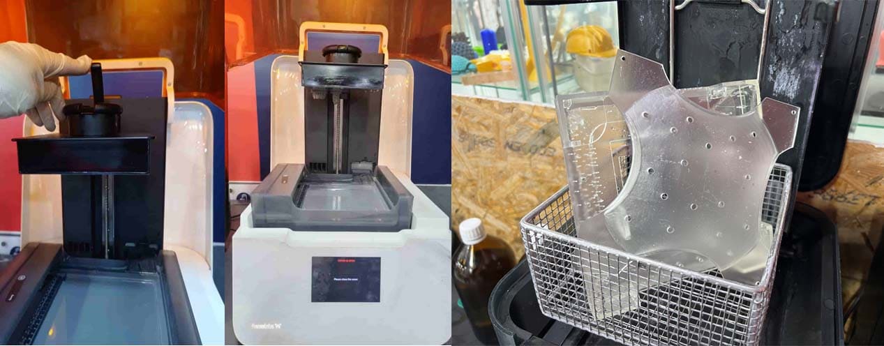
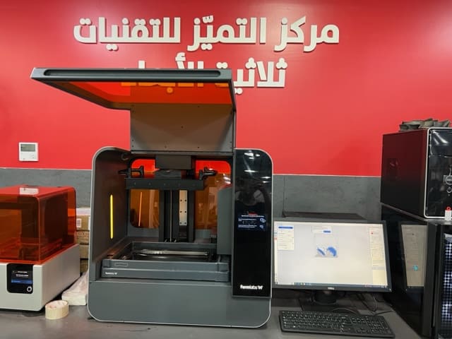
Cone, shaft and dome were printed with 10k rigid clear resin. 0.015mm layer height and I autogenerated the support; after preparing the model, I send it to the machine.
For post-processing I washed the objects in alcohol to remove all resin remaining on the surface, then curing to improve the material’s properties, such as mechanical and chemical. There are a helpful links to guide about how much time to wash and cure. The picture below (from the left), the first picture shows the resin material installed in the small machine, and shows the curing machine.
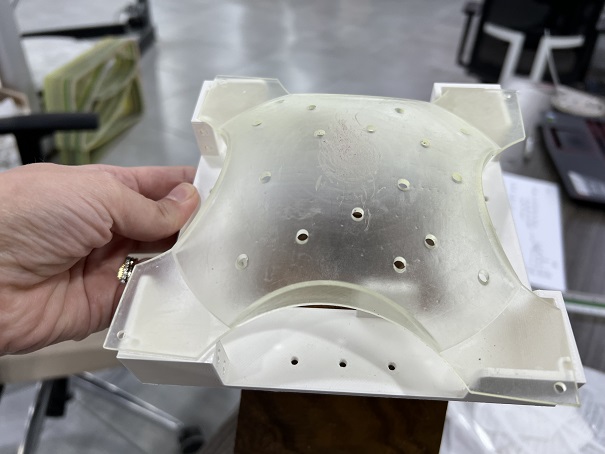
Note: I ended up not using the dome because it made shaft movement a little bit tighter than expected.
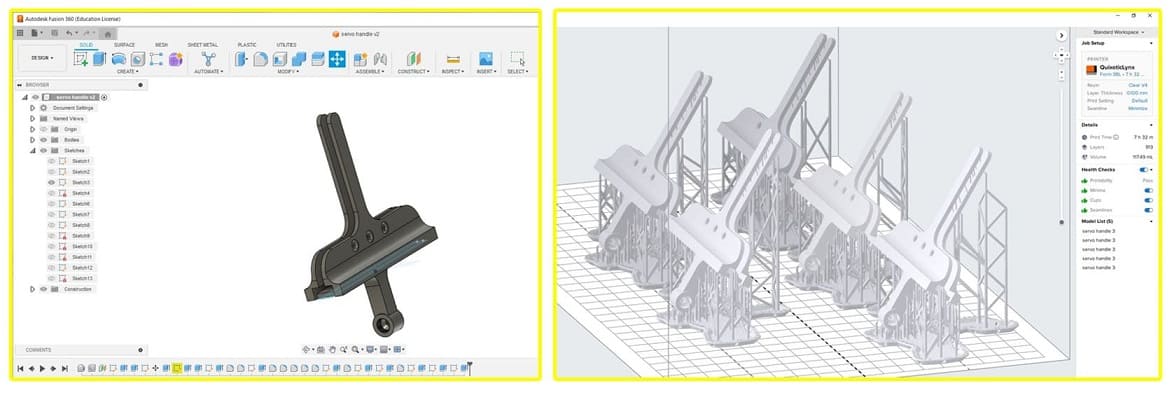
The machine I used is the form 3BL, I prepared the model on perform software
- Tools bar, to setup the model automatically, to scale model, rotate, generate support and print.
- Layers slider, view positions.
- Define printer, material type and layer height.
- Print details, time, number of layers and the amount of material needed.
- Shows the printability of the object, and shows the warnings.
- Build plate volume.
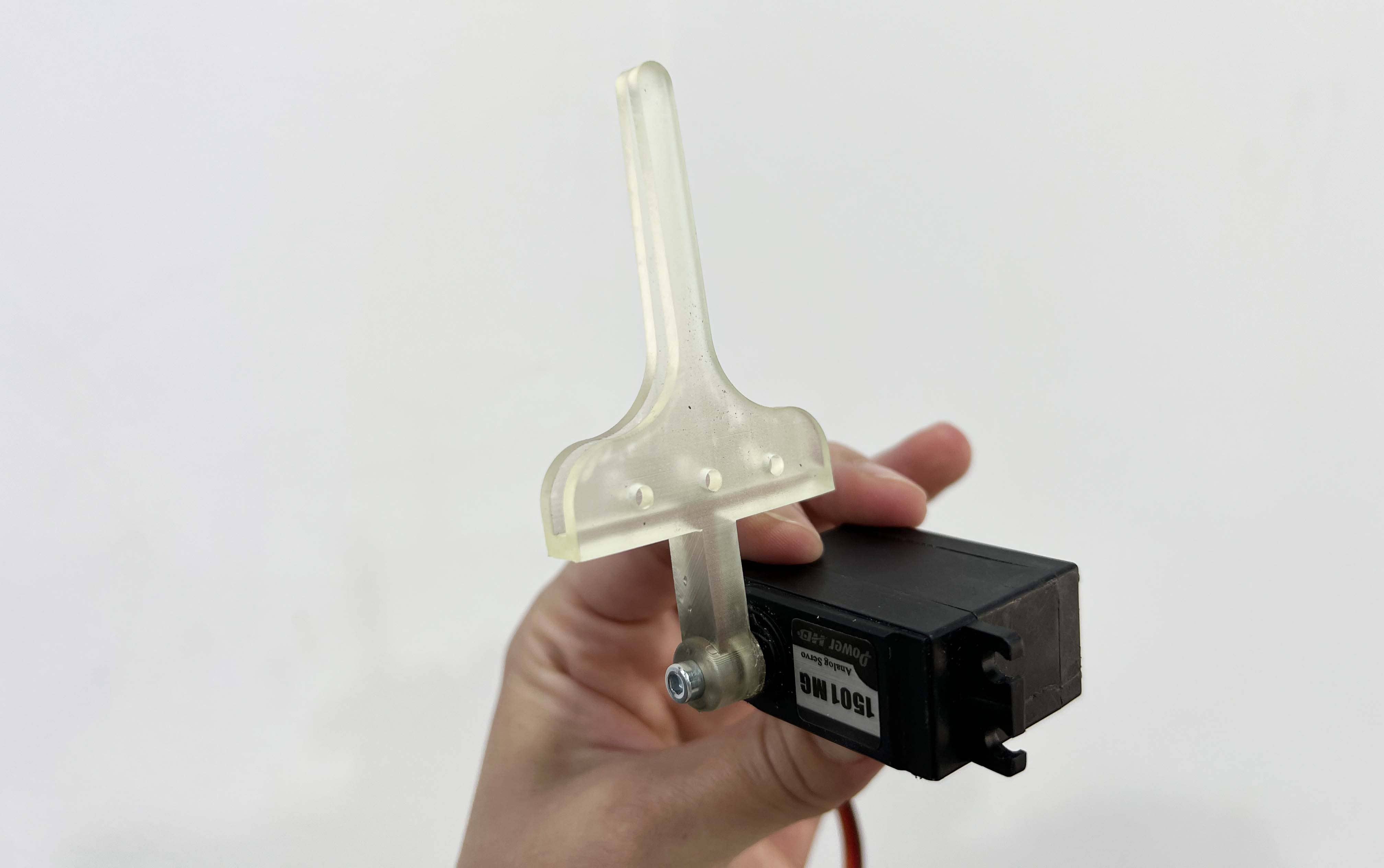
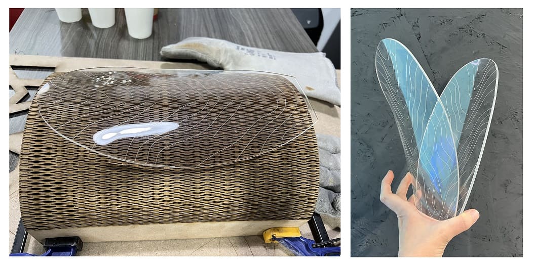
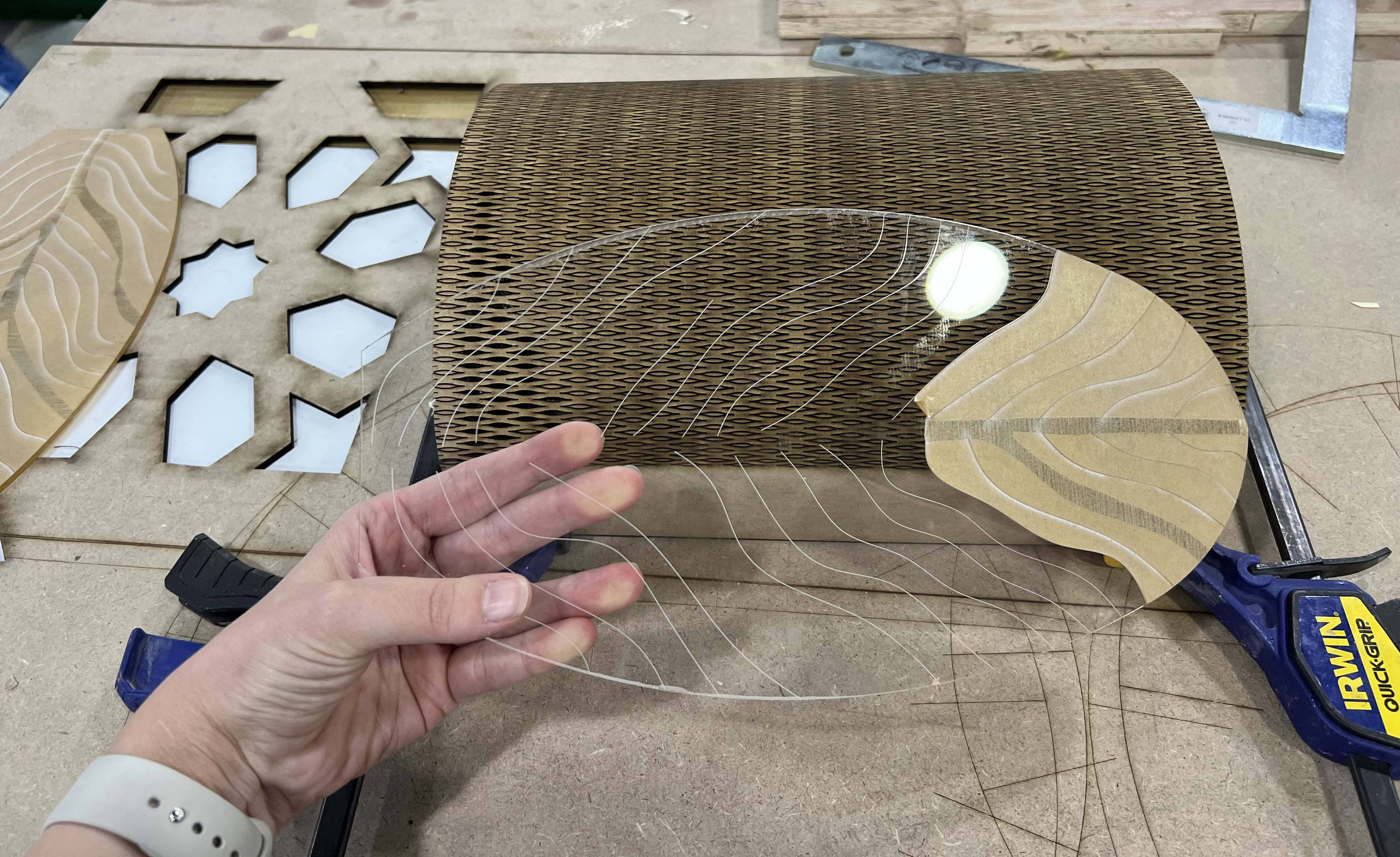
The Petals were acrylic 3mm sheets, I cut them with the laser machine. I shaped them and gave them this organic look through heating them in the oven (they took about 3 minutes) and placing them on the curved surface I created from MDF. I put aluminum foil on the curved surface because MDF was melting from the heat.
My shaft fits the petal perfectly.
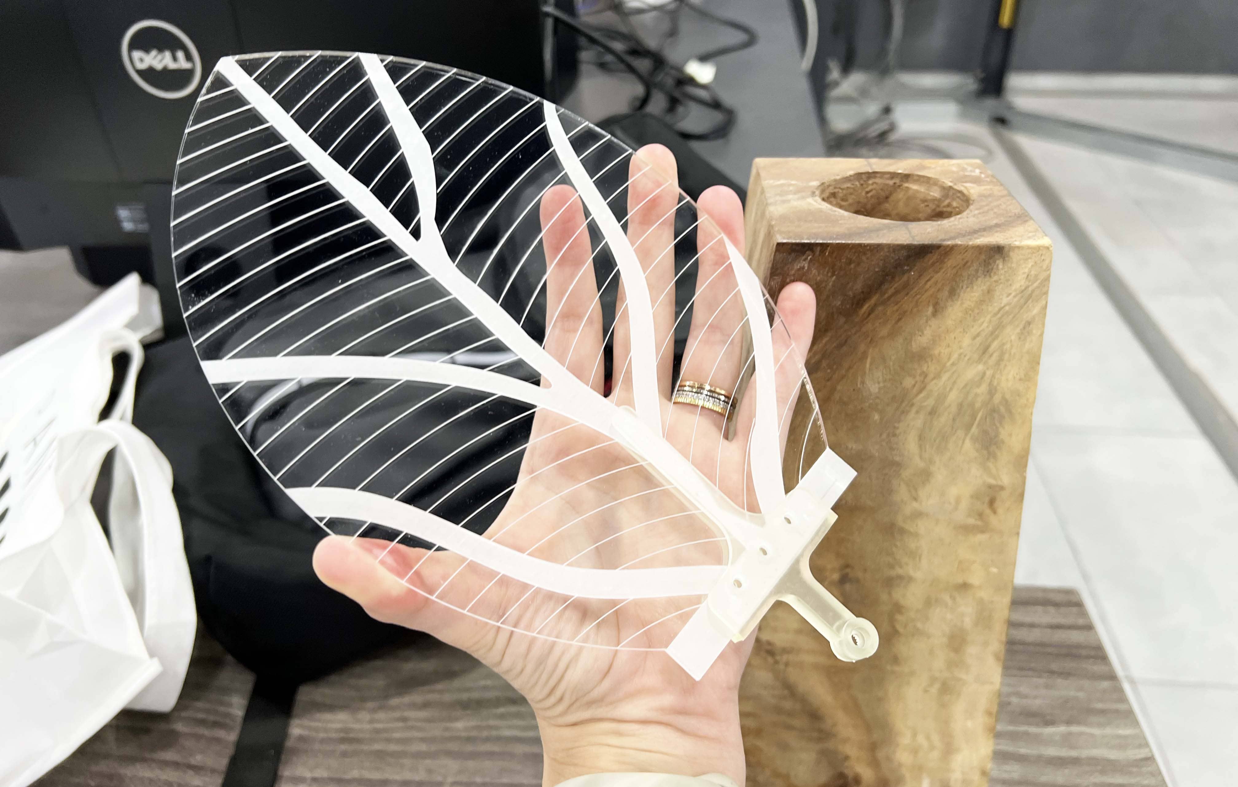
I cut my petals with the laser machine for Cut I used the following settings: Speed=100 Power=.6. engrave I used Speed=100 power=100 i removed the brown cover before enraving otherwise the laser will engrave the brown sheet without engraving acrylic.
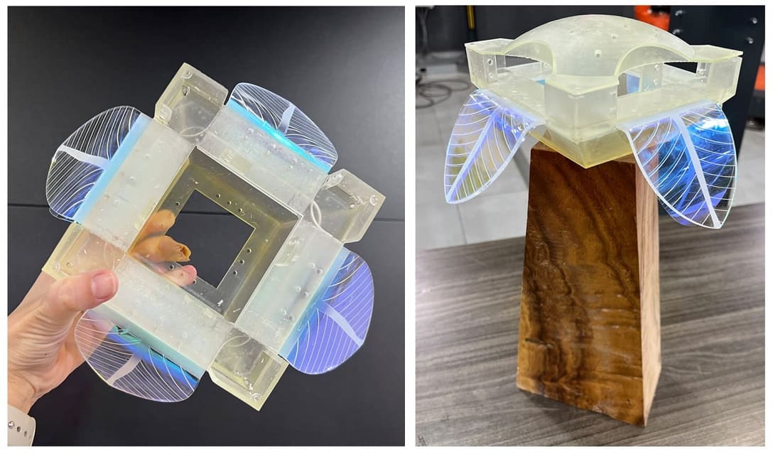
The Esthetics Components: 1- Using of an Iridescent film that will reflect light. 2- Using a wooden solid block which I picked carefully.
The esthetics of my art work is vital for my project’s success, therefore I chose my material wisely. one material I fell in love with is the Iridescent pvc which added a really beautiful effect when I placed it behind my clear acrylic petals

I cut the PVC material manually, I placed my acrylic petal above the film and traced it with a sharp cutter, the result was great actually!
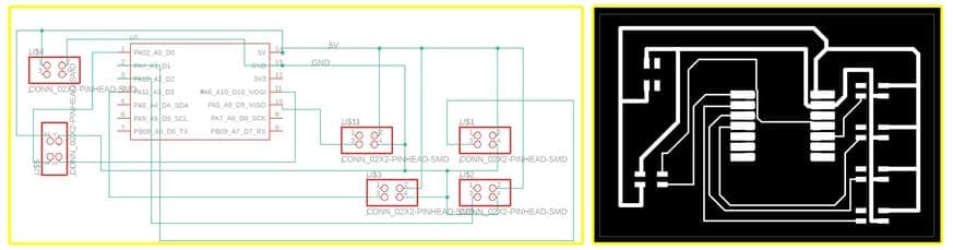
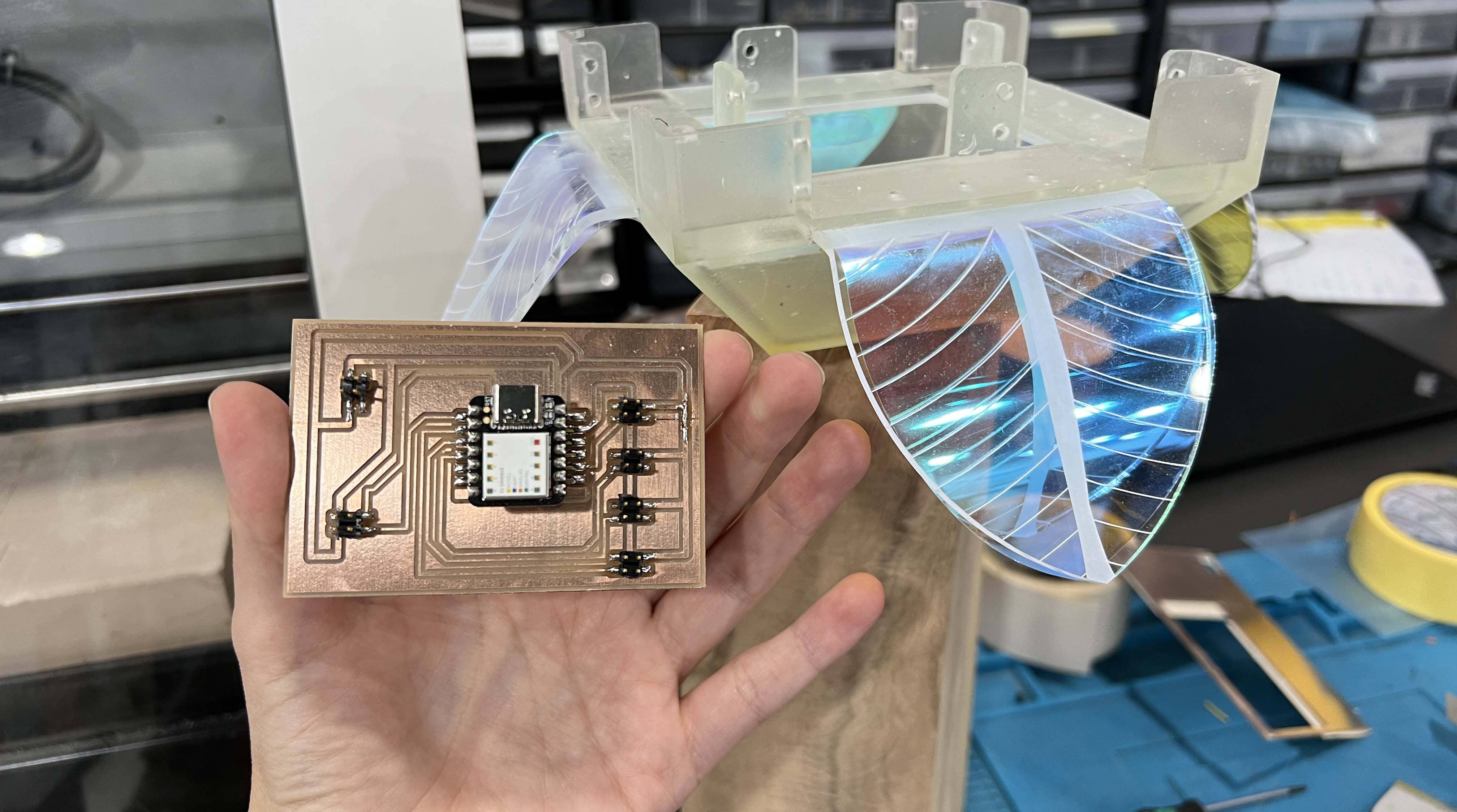
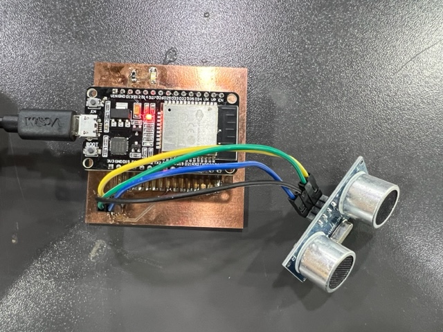
The Electronics
My circuit includes 4 connectors that will be connected to 4 motors, another connector for power source, and a 6th connector for the HC-SR04 ultrasonic distance sensor.
I used seeed_xiao_SAMD21 Microcontroller.
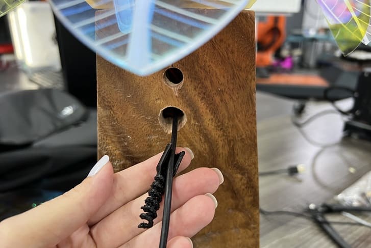
Test 1 Before creating my PCB I had to check the shaft system I designed for my motor on a bread board. (Notice how the shaft broke before I was able to take a video)
Test 2 was to test the torque of my motor, I had to make sure it can actually move my petal using the shaft I designed.
I also needed to know the current and the voltage my motor requires. after testing my motor I found out that my motor requires approximately 1.2 voltage to move while holding the petal and approximately 5 amperes. so I was looking for a power source that can supply my motors with 5volts and 5 amperes.
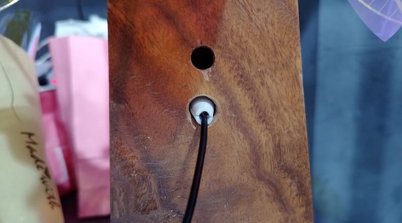
eventually I didn’t find an adapter but I realized I can use my laptop as a power source, I connected the PCB directly to my laptop as a power source for the project from the whole I already created in the back of my wooden base.
I used the regulated power supply machine at the lab.
PCB design of schematic & board:
The motors I used are 1501MG SERVO MOTOR, I also found same size motors but different type at the lab and they worked really well too.
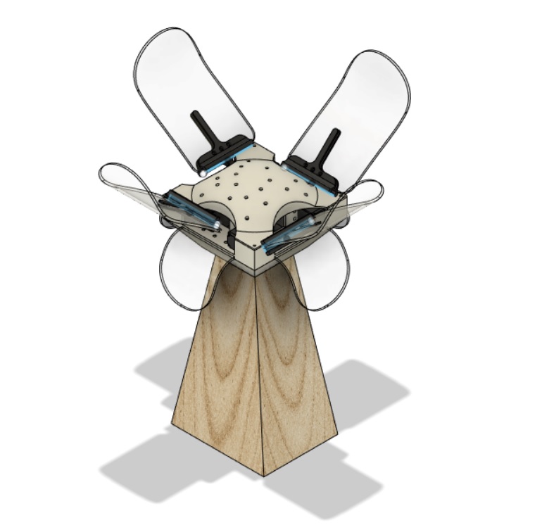
Design integration
Design integration didn’t come out as planned! my motors were placed perfectly and screwed to the base I designed on top of the cone, the PCB and the wires also successfuly hid inside the code, and the wooden base held the sensor and the wire for the power source.
The problem was in the dome that was supposed to cover the cone (the motors and the wires), it didn’t fit with the movement of the shafts and was causing them to break, so I had to make a last minute change and place a pvc sheet above motors, I also placed a 3d printed part which I painted in gold with glue into the plate holding the motors. but I removed it later on bevause I felt it was not very stable.
Also the upper petals where cause the shaft to break although I changed the design multiple times to make it stronger, therefore; I used the PVC sheets only which was nice and flowey.
The design integration “as planned” before fixing motors.
This was the dome I didn’t use eventually
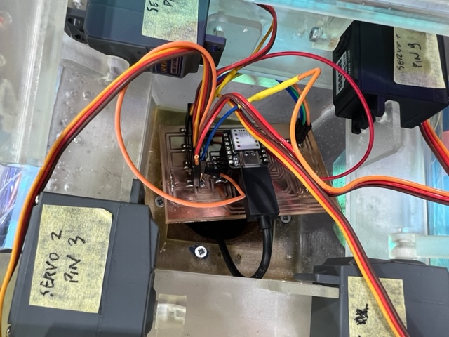
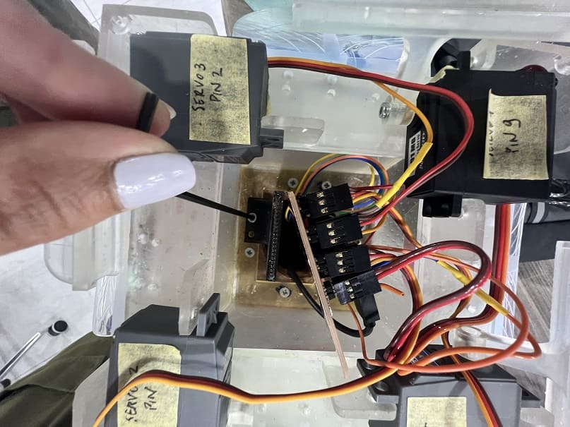
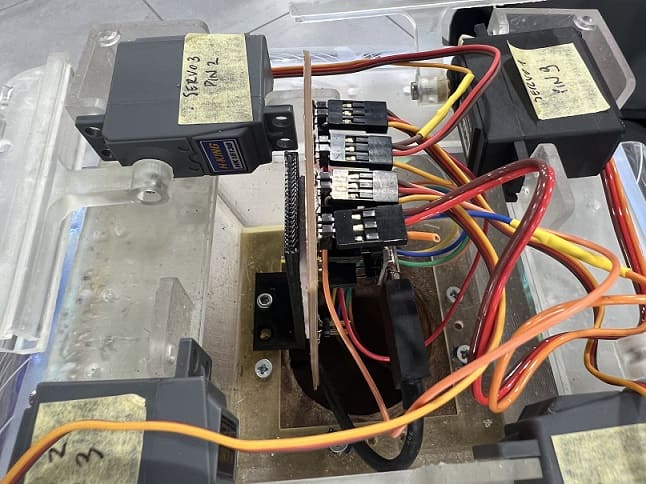
Motors connected to the PCB inside the cone.
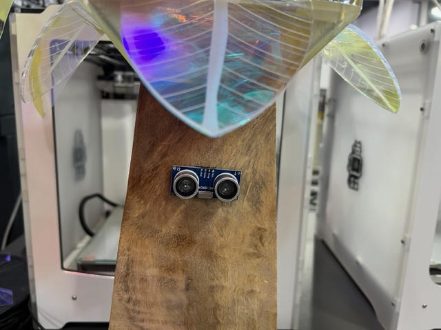
the HC-SR04 Ultrasonic sensor was placed on the wooden base with a glue, the wires went through the 6cm hole I created using the manual drill.
The Global instructor asked me to enhance the integration part by fixing my PCB inside the petal and by creating a strain relief for the power source wire coming out of the wooden block!
Fixing the PCB was challenging because all motors are attached to the top of the cone and it is a little bit hard to manouver and work inside the cone, so I had to think thoroughly about a way to fix it inside. My PCB was sitting at the bottom of the cone which was measured and designed according to PCB dimensions so that it can hold the PCB inside. To fix the PCB i used one of the screw holes I created previously at the cone! I design an L shaped piece and 3D printed it and attached it to my cone with a 3mm screw and used a double sided tape to attach my PCB.
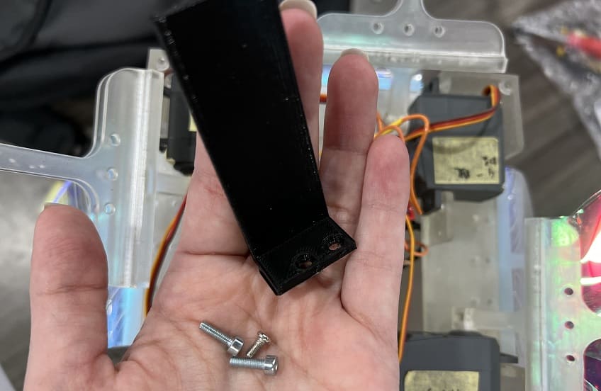
I used an Allen key to fix the screw.
Here is how my PCB was fixed vertically inside the cone.
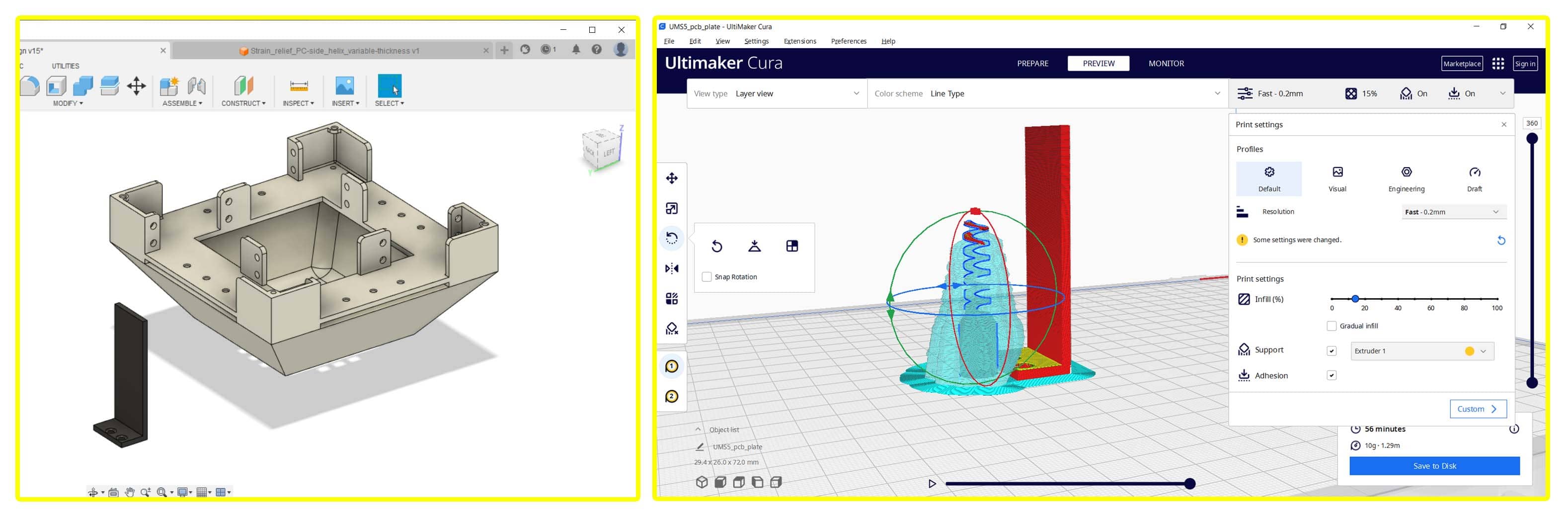
for the Strain Relief I found a good design on thingiverse.com, I printed it but I realized my wire was larger than swirled part.
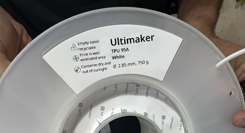
So I designed another part that is a simple cone, I printed it with TPU to have more of a flexible material and here is the result.
The code
/*********
  Rui Santos
  Complete project details at https://RandomNerdTutorials.com/esp32-hc-sr04-ultrasonic-arduino/

  Permission is hereby granted, free of charge, to any person obtaining a copy
  of this software and associated documentation files.

  The above copyright notice and this permission notice shall be included in all
  copies or substantial portions of the Software.
*********/

#include <Servo.h>

// Create a new servo object:
Servo myservo1;
Servo myservo2;
Servo myservo3;
Servo myservo4;

const int trigPin = D0;
const int echoPin = D10;

//define sound speed in cm/uS
#define SOUND_SPEED 0.034
#define CM_TO_INCH 0.393701
#define servoPin1 9
#define servoPin2 3
#define servoPin3 2
#define servoPin4 1

int angle = 0;
long duration;
float distanceCm;
float distanceInch;

int angle_close = 100;  //close when it starts
int angle_open = 140;  //close when it starts

void setup() {
  Serial.begin(9600); // Starts the serial communication
  pinMode(trigPin, OUTPUT); // Sets the trigPin as an Output
  pinMode(echoPin, INPUT); // Sets the echoPin as an Input
  myservo1.attach(servoPin1);
  myservo1.write(angle_close);
  myservo2.attach(servoPin2);
  myservo2.write(angle_close);
  myservo3.attach(servoPin3);
  myservo3.write(angle_close);
  myservo4.attach(servoPin4);
  myservo4.write(angle_close);
}


void loop() {
  // Clears the trigPin
  digitalWrite(trigPin, LOW);
  delayMicroseconds(2);
  // Sets the trigPin on HIGH state for 10 micro seconds
  digitalWrite(trigPin, HIGH);
  delayMicroseconds(10);
  digitalWrite(trigPin, LOW);

  // Reads the echoPin, returns the sound wave travel time in microseconds
  duration = pulseIn(echoPin, HIGH);

  // Calculate the distance
  distanceCm = duration * SOUND_SPEED/2;


  // Prints the distance in the Serial Monitor
  Serial.print("Distance (cm): ");
  Serial.println(distanceCm);

if(distanceCm < 50){

  myservo1.write(angle_open);
  myservo2.write(angle_open);  //when someone is close, position open
  myservo3.write(angle_open);
  myservo4.write(angle_open);
  delay(2000);
} else {
  myservo1.write(angle_close);  //
  myservo2.write(angle_close);  //
  myservo3.write(angle_close);
  myservo4.write(angle_close);  //
}
}
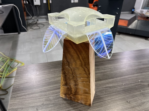
Hero Shot
other pages with information on my final project:
Application & Implication Invention, intellectual property and income project Development
Files download
shaft design file-fusion360 leafs design cone design flower_board flower_schematic L_SHAPED_ELEMENT Strain_Reflief_cone