Project Development
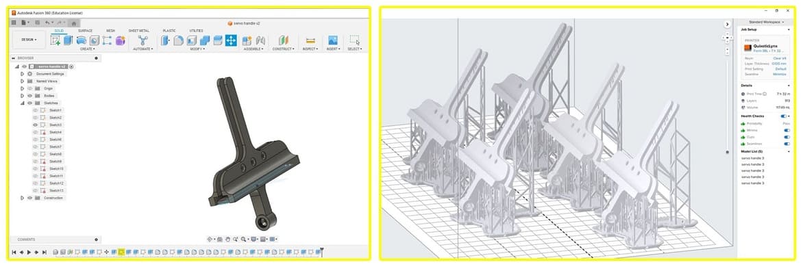
Computer design Design is complete! time for implimentation!
![]()
The Block I found a wooden block with the right dimension (30cm*8cm) I cut it and drilled it from the middle to start working on it.
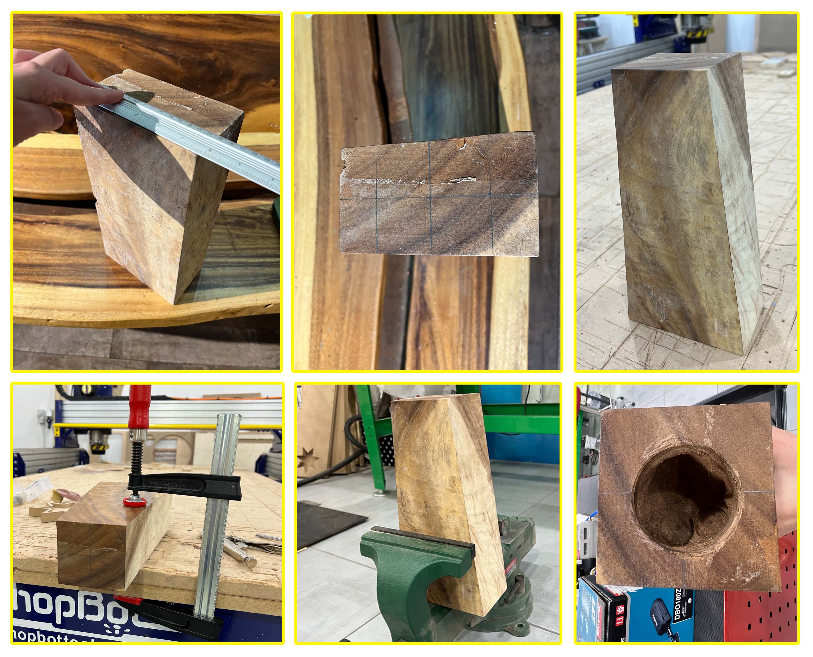
I measured my block and drew lines where I’d like to make a hole. I used the manual drill after fixing my block. At first I used a hole-saw end mill to create the opening and then a flat end mill to take out as much wood as possible.
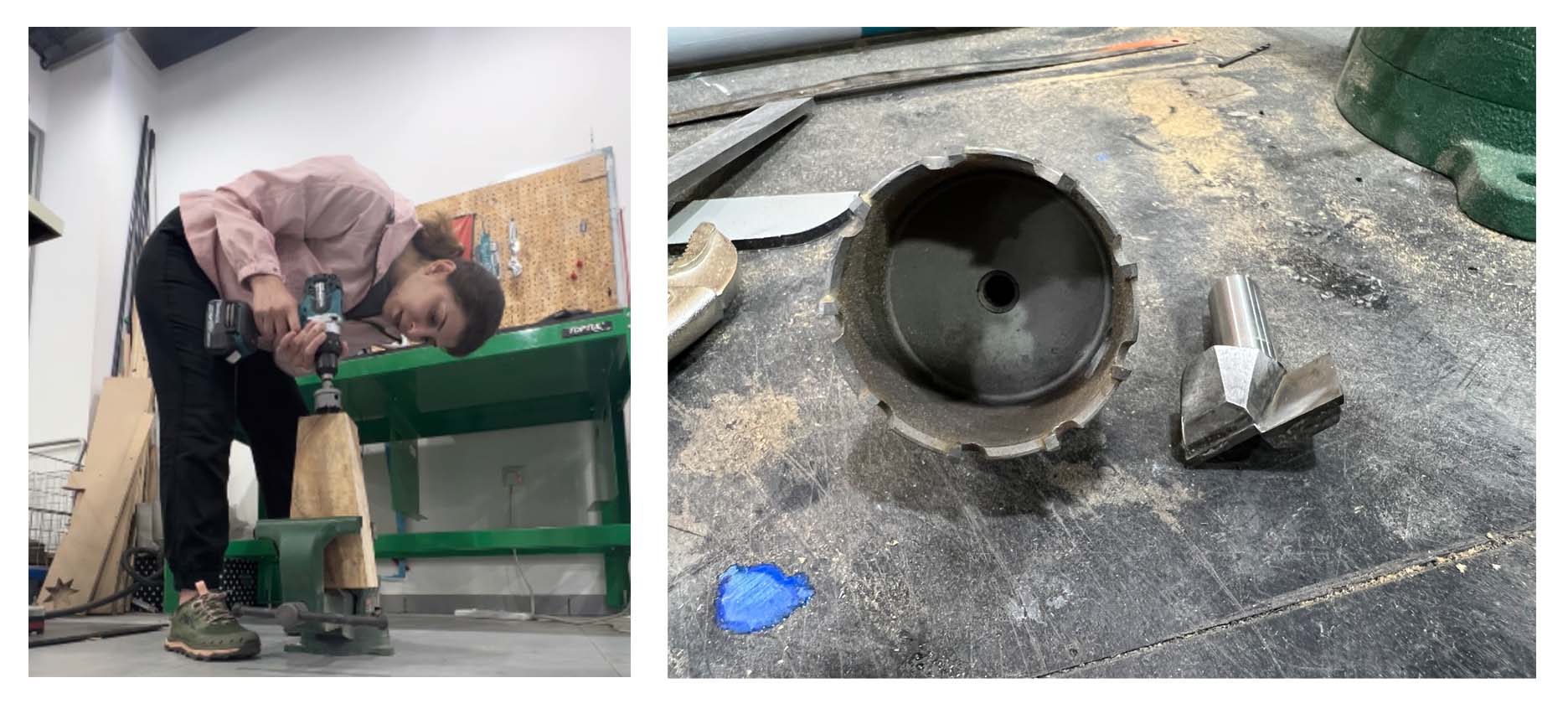
I also made three other holes using the manual drill, two on the back for power source wire and another one on front for the sensor, I used glue to attach the sensor on the wooden block. I used a 6cm flat end-mill on the manual drill.
The Cone was 3d printed with transparent resin.
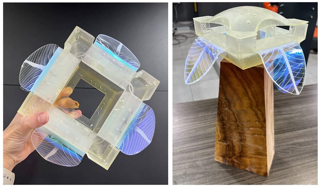
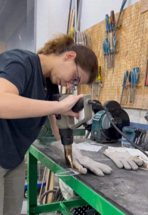
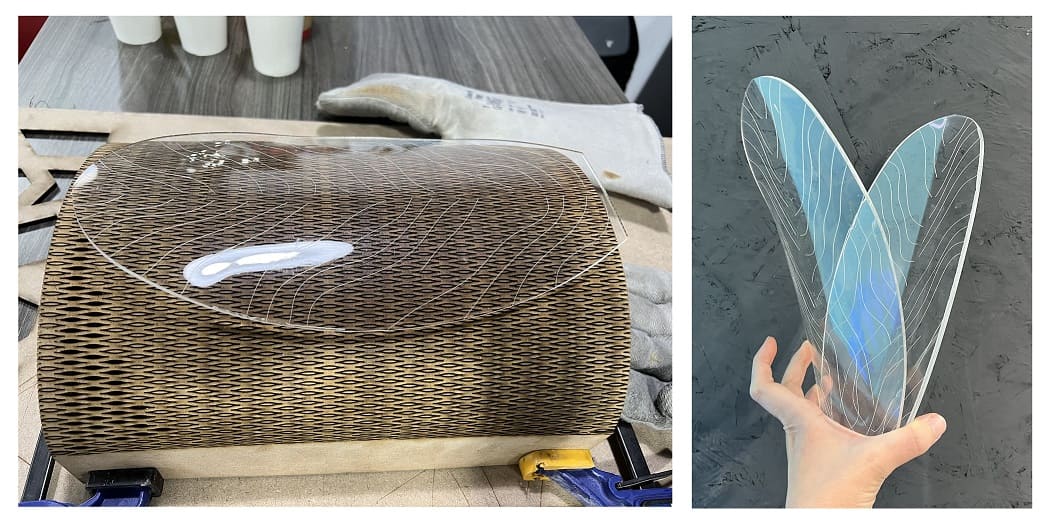
To bend the lower petals, I used a heat gun after taking safety measures of using heat-proof gloves and on a heat-proof table surface.
The Shaft was 3d printed with transparent resin. the screw hole is 3mm, i made 3 holes on each shaft and each petal.
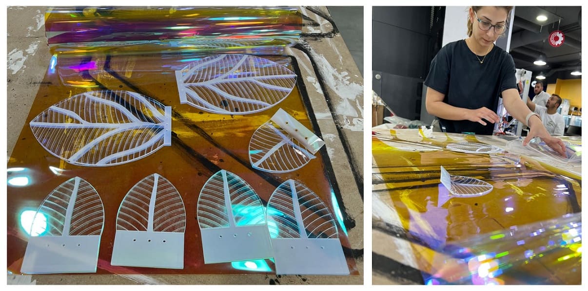
The Petals were acrylic 3mm sheets, I cut them with the laser machine. I shaped them and gave them this organic look through heating them in the oven (they took about 3 minutes) and placing them on the curved surface I created from MDF. I put aluminum foil on the curved surface because MDF was melting from the heat.
What worked and what didn’t?
Motors worked well, but my shaft broke easily therefore I am changing the design to make the holder stronger and I will cut smaller petals.
I resolved the shaft and made smaller petals but integrating of all components in my design didn’t work well! I couldn’t fix the dome that was supposed to hide all motors below it, the shafts were in the way! I had to choose between the shafts and the dome! I had to make a last minute decision and attach a pvc film only which is still a see-through for all motors and wires.
I believe wooden base and cone were integrating well, they held the PVC and were connected well to my motors and to my sensor. the only part that didn’t serve as I wanted was the dome.
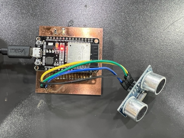
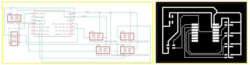
The Electronics
What questions need to be resolved?
-
What program do I use for my video? I ended up using “Movie maker”, it is free and very easy!
-
What program do I use for voice recording? I ended up using my phone and upload it as an MP3 to the video.
-
No other questions come to my mind.
What will happen when?
What will happen if my shaft breaks again before submission? I will print few extra ones from the new design.
What have you learned?
How casn I answer this without writing a book! This whole program has been a huge learning curve for me!
I learned that I love design! I want to focus on this aspect of product design in the future!
I learned that i am not very fond of electronics but I have to learn more about them to become a better designer! I will start by learning the different parts other than the ones I used in my assignments and final project!
I learned that testing is very vital for the success of the project! start testing with a bread board and a simple code.
I learned that I should simplify what I wish to make and after I make it I can add more stuff! spiral movement!
I learned that I function well under pressure! I didn’t expect to go through multiple family challenges (my child got sick multiple times) yet I was able to deliver my project!
I learned that I still cannot plan and put a schedule but I can start working ahead of time to avoid and delays.
What tasks remain?
Coding and testing of my code.
**NOTE: I am attaching the final code below after I submitted my project for documentaion purposes.
Coding
Below is the code I used with my PCB.
/*********
  Rui Santos
  Complete project details at https://RandomNerdTutorials.com/esp32-hc-sr04-ultrasonic-arduino/

  Permission is hereby granted, free of charge, to any person obtaining a copy
  of this software and associated documentation files.

  The above copyright notice and this permission notice shall be included in all
  copies or substantial portions of the Software.
*********/

#include <Servo.h>

// Create a new servo object:
Servo myservo1;
Servo myservo2;
Servo myservo3;
Servo myservo4;

const int trigPin = D0;
const int echoPin = D10;

//define sound speed in cm/uS
#define SOUND_SPEED 0.034
#define CM_TO_INCH 0.393701
#define servoPin1 9
#define servoPin2 3
#define servoPin3 2
#define servoPin4 1

int angle = 0;
long duration;
float distanceCm;
float distanceInch;

int angle_close = 100;  //close when it starts
int angle_open = 140;  //close when it starts

void setup() {
  Serial.begin(9600); // Starts the serial communication
  pinMode(trigPin, OUTPUT); // Sets the trigPin as an Output
  pinMode(echoPin, INPUT); // Sets the echoPin as an Input
  myservo1.attach(servoPin1);
  myservo1.write(angle_close);
  myservo2.attach(servoPin2);
  myservo2.write(angle_close);
  myservo3.attach(servoPin3);
  myservo3.write(angle_close);
  myservo4.attach(servoPin4);
  myservo4.write(angle_close);
}


void loop() {
  // Clears the trigPin
  digitalWrite(trigPin, LOW);
  delayMicroseconds(2);
  // Sets the trigPin on HIGH state for 10 micro seconds
  digitalWrite(trigPin, HIGH);
  delayMicroseconds(10);
  digitalWrite(trigPin, LOW);

  // Reads the echoPin, returns the sound wave travel time in microseconds
  duration = pulseIn(echoPin, HIGH);

  // Calculate the distance
  distanceCm = duration * SOUND_SPEED/2;


  // Prints the distance in the Serial Monitor
  Serial.print("Distance (cm): ");
  Serial.println(distanceCm);

if(distanceCm < 50){

  myservo1.write(angle_open);
  myservo2.write(angle_open);  //when someone is close, position open
  myservo3.write(angle_open);
  myservo4.write(angle_open);
  delay(2000);
} else {
  myservo1.write(angle_close);  //
  myservo2.write(angle_close);  //
  myservo3.write(angle_close);
  myservo4.write(angle_close);  //
}
}