Computer Controlled Machining
WELCOME TO WEEK 7 ASSIGNMENT
The machine
Machine: SHOP-BOT Software: vcarve File Download:doll_house
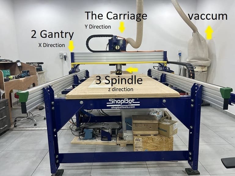
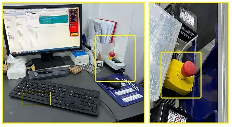
NOTE stay close to the PC so you can either pause the job through the space button on the keyboard or through stopping the job with the red button that comes with the machine.
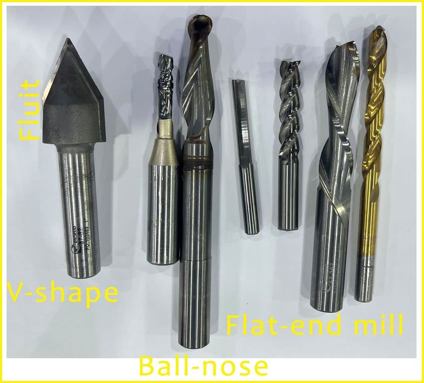
There are several tools that can be used in a hand router and in the CNC router machine, we must learn which tools can carve the shape we designed to get best results. Tools are:
| Tool | Material | Charachterestics | Direction |
|---|---|---|---|
| 1-Flat end-Mill | High Speed Steel | Used for machines with low RPM | Axis |
| 2- Flat end-mill | Carbide | Used with wood, steel & plastic | Axis & Radial |
| 3- Ball-Nose | Carbide | for 3D geometry & grooves | Axis & |
| 4- V shape | Carbide | for engraving ornaments | |
| 5- Bull Nose | Carbide | used for steel curring. |
All tools have a direction for the spiral blade: eithr Counter Clock Wise or Clock Wise.
- CCW also known as UP-Cut : Used for metals and plastic.
- CW also known as down-cut : Used for cutting wood.
NOTE The designed file have to be through a software that can be saved as DXF, The design file will later be opened through a CAM FILE (Tool path file: V carve and Numerical Control file NC: Shopbot Software)
Up Milling VS Down Milling
Advantages of each milling diriction
| Up Milling (conventional) | Down Milling (Climb) |
|---|---|
| suitable for soft material such as foam. | helps stabilize the cutting material on the machine. |
| suitable for material with lower thickness. | Better surface finish |
Calculations for VCARVE software
There are several data that must be inserted before starting the job. some are provided by manifacturer and some are calculated. for example some of these values are: - Fluit Length : (Provided by manifacturer) - Fluit diameter : (provided by manifacturer) - Number of Teeth (Z) : (provided by manifacturer) - Feed per teeth (Fz) : (provided by manifacturer) - Chipload : (Provided by manifacturer) - Feedrate : (Calculated from Chipload) - Width of cut : Equals Fluit diameter - Depth of cut : 50-60% from fluit diameter - RPM (N) : (maximum RPM determined by manifacturer, but you should never use the maximum speed) - Speed of feed : Calculated through this equation. Vf = n X fz X Z
So for example I used 1400 RPM, for a 0.1 feed per teeth tool and a 2 teeth tool, the Vf in this case is 2,800 mm/minute.
NOTE - Runout: is the tendency to spin the tool around a centerpoint that is not the tool’s center. It makes the tool wobble instead of spinning cleanly and increases chip loads. - Feed rate the speed at which the cutter engages the part and is typically measured in units/minute.
Fixing the Work-piece
Designing and cutting my DollHouse
FIRST I designed my doll-house on fusion360, I felt my design was huge and had multiple components, I guess I freaked out and decided to go with a simple straight-forward design as shown in second picture. I drew my bone nose while designing my doll-house on fusion360 although it is much easier to draw on VCarve. I saved my designed files as .DXF
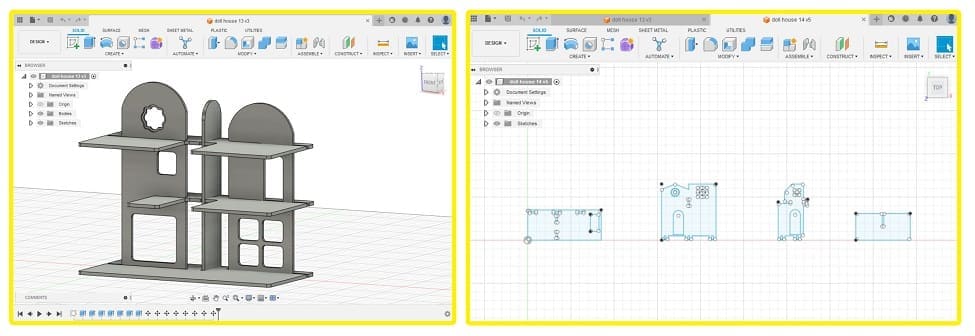
NOTE I will always have my project in 3D! I realized how vital it is to see your design assembeled before creating it!
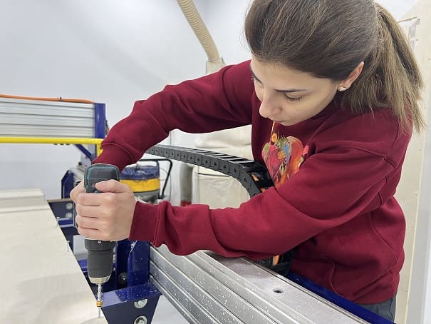
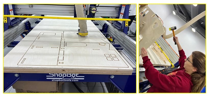
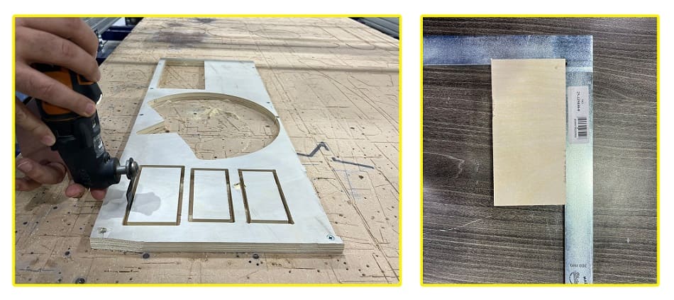
SECOND clean your surface and fix your working piece. The machine has MDF sacrifice board fixed on bed. If the endmill penetrates the work piece the extra cut would happen on the sacrifice sheet. This way we make sure machine body and tool won’t be destroyed. Holes were drilled to work piece and wood screws used to fix it to sacrifice board. Note that when we work on software, we define “Boarder Gap” to be 30mm. Cutting will not be happening on this area, so we can use it to put the screws. On the other hand, if the work piece is misaligned to the machine axes, the boarder gap will compensate misalignment and cuts will be inside work piece. My board is a 18mm Plywood
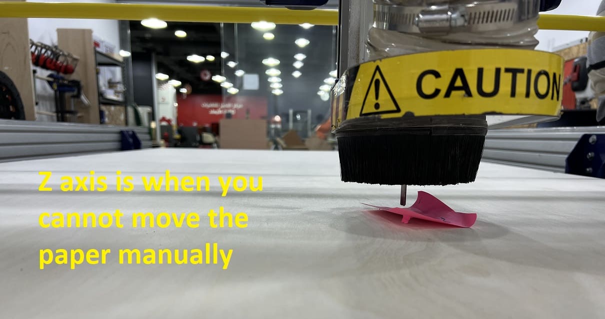
THIRD calibrate your machine on the X,Y,Z axis.
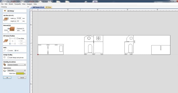
FOURTH Open VCarvePro and click on “Open an existing file”. Locate the dxf file and open it. Dxf file will be displayed and “Job Setup” menu opens. Insert job settings and click “Ok”. The board I used is 2440mm x 1220mm and measured thickness is 18mm.
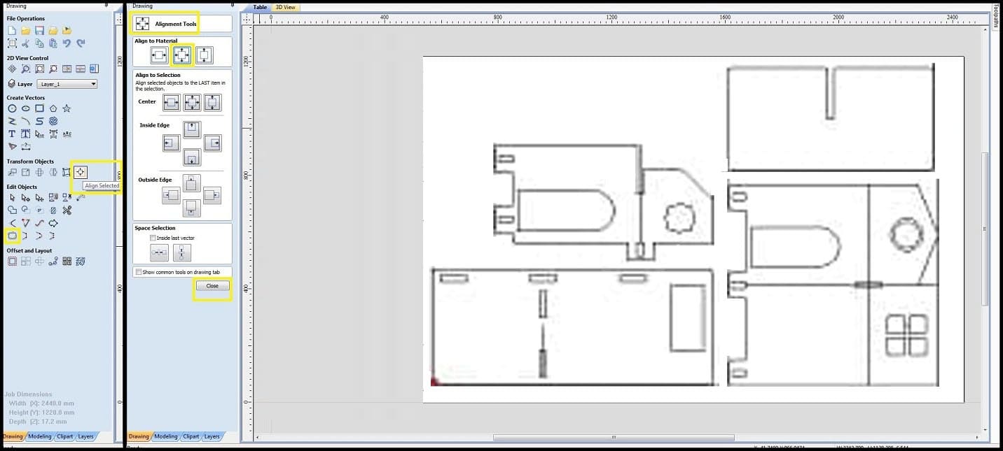
FIFTH Select all objects in the drawing and click on “Align Selected Objects”. “Align Tools” menu opens and in “Align to Material” select to center drawing to working board center. You can see there is a boarder gap around objects, which made in Inkscape file. Click “close”.
select all your components and press join to make sure your lines are connected, choose 0.02 tolerance.
Group all your components through the group button.
FIFTH in toolpath operations click on “profile toolpath”, in “tool” menu define your end-mill according to your tool’s datasheet, my tool had the following properties:
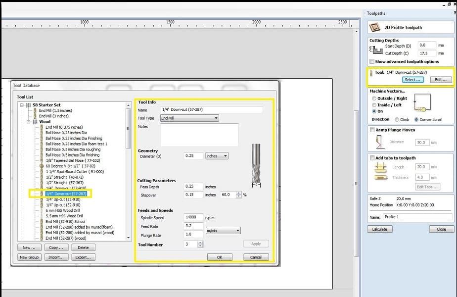
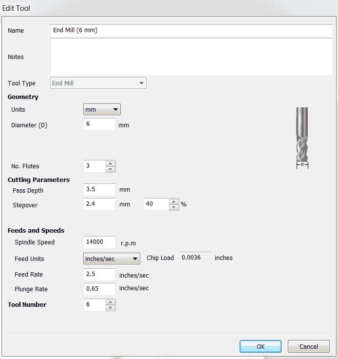
- **Cut depth:** 18.3mm (which I changed later to 18.6 because it didn't cut some parts)
- **Tool:** 6mm end mill.
- **Machine vector:** Outside
- **Pass Depth:** 4.2mm
- **Step over:** 2.4mm 40%
- **Spindle Speed:** 1400 RPM
- **Feed rate:** 53 inches/minute.
**note: you have to calculate the feedrate as follows: Chip Load = Feed Rate / (RPM x # of Flutes), where chip load in inches per flute, feed rate in inches per minute and RPM in revolution per minute. calculating feed rate
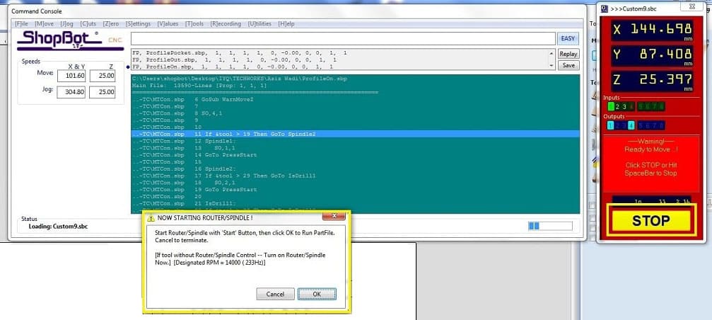
SIXTH Calculate your toolpath In “Position” choose mode; “Preview” to check your toolpath or “Move/Cut” to start actual machine cutting. Click on “Cut Part” and select toolpath(s) to preview or cut. For actual machine cutting the machine will ask to start the spindle. If spindle already started, click “Ok” and machine will start working as per selected toolpath. Remember to start the dust extractor. When the machine starts working, you cannot move the mouse pointer away from the “Stop” button. This is a safety feature. Machine could be stopped also using the space bar in keyboard or machine emergency button.
Hero Shot
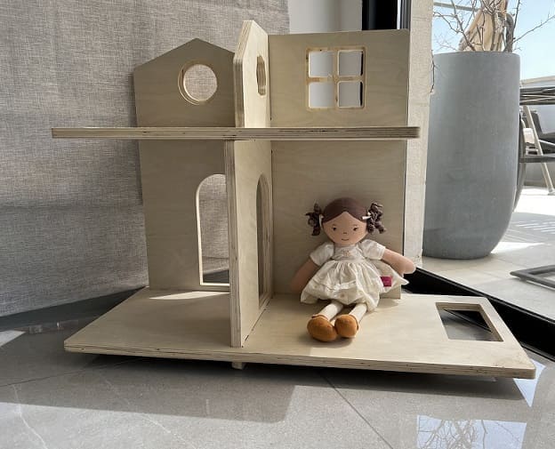
Fulla has a new house <3
Group Assignment
- We completed our safety training: 1- Wear your protective equipments especially when working with metal. 2- don’t wear any loose jewlery, hair or clothing. 3- keep safety distance between you and the machine while it is operating. 4- perform regular maintainance. 5- make sure sacrifice bed is clean. 6- fix your work piece with screws properly to avoid flying parts.
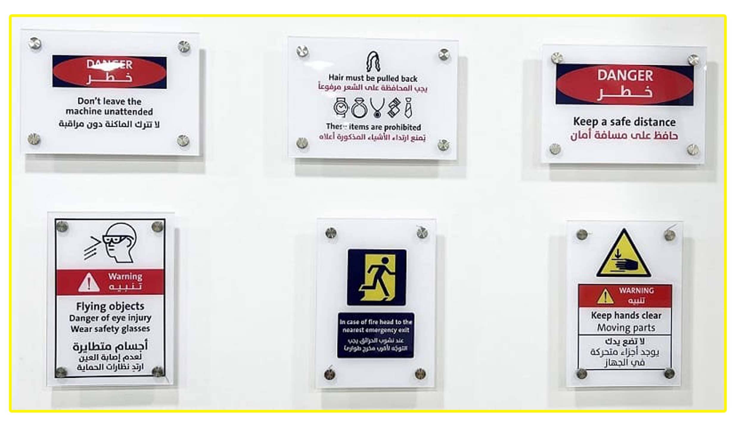
We also learned about the two emergency buttons that can stop the machine anytime we sense any problem. and the space button on the PC that can pause the job.
- We tested the alignment of the first piece (outside milling), edges were 90 degrees sharp with a fillet on the corners although our drawing had sharp corners. the difference between design and cut piece is caused by the tool radius.
- in order for the second rectangule to fit inside the third rectangule, we made a difference in clearance (.3mm) and we drew a dog bone shape on the third piece corners to allow our tool to move inside the dog bone shape instead of making a fillet in our rectangule’s corners.

We also Tested runout, alignment, fixturing, speeds, feeds, materials and toolpaths for your machine.
NOTE the working piece must be fixed with screw as shown in the picture.