14. Networking and Communications
Objectives
- Design, build, and connect wired or wireless node(s) with network or bus addresses. Group assignment Group Assignment page
- meas
- Send a message between two projects.
The Fourteenth week’s class of my fab academy life took place and the professor Neil class started as usual,this week assignmend as khown as Networking and Communications
In the begining of this week, I tried to learn about communication protocol and networks from internet.
Serial Communication: A Communication method that uses one or two transmission lines to send and receive data, and that data is continuously sent and received one bit at a time..
 Parallel Communication: A Communication method of sending several data signals simultaneously over a transmission link at one time. It comprises of several wired channels in parallel

Parallel vs Serial Cables
The cables used for parallel and serial communication look quite a bit different from each other. Parallel cables are generally thicker and shorter than serial cables, and typically have larger more complex connector heads.
Parallel Cables
Parallel cables are most easy to spot if you can see individual pins visible on the connector head as seen in the picture below. These pins are directly linked to an individual wire in the cable. For every pin on the male side of the connecter head, you can find an input slot on the female end of the cable. The connection is uninterrupted from one end to the other. The cable is generally thick and stiff feeling when compared to serial cables because of the number of wires that are in the cable.

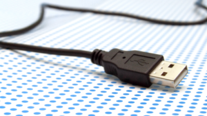
Serial Cables
Serial cables are much more common to spot in everyday life. The USB cable is an example of a serial style cable. As you can see the connector head looks substantially different than the parallel cable simply because it is smaller and does not have visible pins. Another differentiating aspect is the thickness of the cable.
 for mode details for communication
So I decided to take the serial communication are used I explored and learned to communication in previous student’s documentaion Rahul,Jogin Francis,Jaseel,Sibu,becouse in this week I have no idea to this week assignment
Let’s Start
In serial communication I decided to use the nRF24l01 module, so I want two boards then I started to make board

Then I take to milled the PCB
 After milled I solder the components
Then after that I start the basic communication programming first I add the librarys At ATTYNI and nRF24L01 because I used to ATTYNI1614 and nRF24L01
After I connect the Transmitter And I upload the programming This is the code
//Include Libraries
#include <SPI.h>
#include <nRF24L01.h>
#include <RF24.h>

//create an RF24 object
RF24 radio(9, 8);  // CE, CSN

//address through which two modules communicate.
const byte address[6] = "00001";

void setup()
{
  while (!Serial);
    Serial.begin(9600);

  radio.begin();

  //set the address
  radio.openReadingPipe(0, address);

  //Set module as receiver
  radio.startListening();
}

void loop()
{
  //Read the data if available in buffer
  if (radio.available())
  {
    char text[32] = {0};
    radio.read(&text, sizeof(text));
    Serial.println(text);
  }
}
Then I connect Receiver repet the same mathod
//Include Libraries
#include <SPI.h>
#include <nRF24L01.h>
#include <RF24.h>

//create an RF24 object
RF24 radio(9, 8);  // CE, CSN

//address through which two modules communicate.
const byte address[6] = "00001";

void setup()
{
  while (!Serial);
    Serial.begin(9600);

  radio.begin();

  //set the address
  radio.openReadingPipe(0, address);

  //Set module as receiver
  radio.startListening();
}

void loop()
{
  //Read the data if available in buffer
  if (radio.available())
  {
    char text[32] = {0};
    radio.read(&text, sizeof(text));
    Serial.println(text);
  }
}
Then afte I decided serial communication with using serial monitor
I tryed it more time but it was faild it no worked
So I changed the serial monitor communication method , I selected to button and led blink with serial communication
So I take wand to A switch then I take my friend Joshwin’s PCB switch module
This si the board

I connect board to the SCL SDL ports
After that I connect the board to computer and upload tthe code
Transmitter Code
#include <SPI.h>
#include <nRF24L01.h>
#include <RF24.h>

#define led 3

RF24 radio(1, 0); // CE, CSN
const byte addresses[][6] = {"00001", };
boolean buttonState = 0;

void setup() {
  pinMode(3, OUTPUT);
  radio.begin();
  radio.openReadingPipe(1, addresses[0]); // 00001
  radio.setPALevel(RF24_PA_MIN);
}

void loop() {
  delay(5);

  radio.stopListening();
  int potValue = analogRead(A0);
  int angleValue = map(potValue, 0, 1023, 0, 180);
  radio.write(&angleValue, sizeof(angleValue));

  delay(5);
  radio.startListening();
  while (!radio.available());
  radio.read(&buttonState, sizeof(buttonState));
  if (buttonState == HIGH) {
    digitalWrite(led, HIGH);
  }
  else {
    digitalWrite(led, LOW);
  }
}
Receiver Code
#include <SPI.h>
#include <nRF24L01.h>
#include <RF24.h>


#define button 7

RF24 radio(1, 0); // CE, CSN
const byte addresses[][6] = {"00001", };
boolean buttonState = 0;

void setup() {
  pinMode(button, INPUT);

  radio.begin();
  radio.openWritingPipe(addresses[0]); // 00001

  radio.setPALevel(RF24_PA_MIN);
}

void loop() {
  delay(5);
  radio.startListening();
  if ( radio.available()) {
    while (radio.available()) {
      int angleV = 0;
      radio.read(&angleV, sizeof(angleV));
     }
    delay(5);
    radio.stopListening();
    buttonState = digitalRead(button);
    radio.write(&buttonState, sizeof(buttonState));
  }
}
This is the result
All files Download