7. Electronics Design
Objectives
- Redraw an echo hello-world board
- add (ai least ) abutton and LED (withy current limiting resistor)
Group Assignment Group Assignment page
- Use the test equipment in your lab ti observe the operation of a micro controller circutr board.
The Seventh week’s class of my fab academy life took place and the professor Neil class started as usual,this week assignmend as khown as 3D Scanning and printing
Group Assignment
In this week, we learned to use different electronic test equipments.
Testing Equipments

FLUKE 101 Pocket Digital Multimeter

it measures AC/DC voltage, Current, Continuity, Resistance, Frequency, Capacitance
INSTEK GPD-3303D Power Supply

Instek GPD-3303D is a Multiple Output Programmable Linear D.C. Power Supply it have 2/3/4 Independent Isolated Output, LED Display, 1mV/1mA(GPD-2303D/GPD-3303S/GPD-4303S), 100mV/10mA(GPD-3303D) 4 Sets Save/Recall, Tracking Series and Parallel mode, USB Standard Interface, and Lab view driver
UNISOURCE DS-1100 100 MHZ, 2 CH, Digital Storage Oscilloscope
photo_2022-03-09_19-15-47 (2).jpg

The digital storage oscilloscope is an instrument which gives the storage of a digital waveform or the digital copy of the waveform. It allows us to store the signal or the waveform in the digital format, and in the digital memory also it allows us to do the digital signal processing techniques over that signal. The maximum frequency measured on the digital signal oscilloscope depends upon two things they are: sampling rate of the scope and the nature of the converter. The traces in DSO are bright, highly defined, and displayed within seconds. it have 100 MHz bandwidth, 1 M Memory, USB storage, RS232C & J45 interface,4000 point record length for each channel,Multi-waveforms math, FFT Function, Cursor & Track measurement, Waveform Record & Recall, Trigger Mode for Edge, Video, Pulse Width, Slope & Alternate
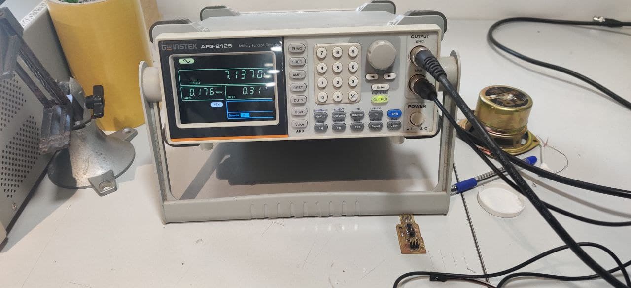
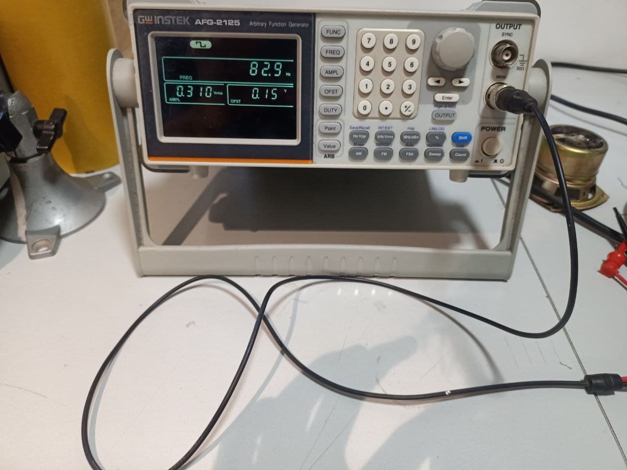
INSTEK AFG-2100/2000 SERIES ARBITRARY FUNCTION GENERATOR
 https://fabacademy.org/2022/labs/kochi/students/joshwin-johnson/images/photo_2022-03-09_19-15-47.jpg
A function generator is a specific form of signal generator that is able to generate waveforms with common shapes. Unlike RF generators and some others that only create sine waves, the function generator is able to create repetitive waveforms with a number of common shapes. The AFG-2100/2000 Series Arbitrary Function Generator is a DDS (Direct Digital Synthesized) based signal generator designed to accommodate the Educational and Basic Industrial requirements for an accurate and affordable signal source covering the output of Sine, Square (Pulse), Ramp (Triangle), Noise and Arbitrary waveforms.it have 0.1Hz to 25MHz with in 0.1Hz Resolution, Sine, Square, Triangular, Noise and, Arbitrary Waveform, 1% ~ 99% adjustable duty cycle for Square Waveform, Waveform Parameter Setting Through Numeric Keypad Entry & Knob Selection, Amplitude, DC Offset and Other Key Setting Information Shown on the 3.5” LCD Screen Simultaneously, AM/FM/FSK Modulation, Sweep, and Frequency Counter Functions (AFG-2100 only), PC Arbitrary Waveform Editing Software
Let’s start
In this week assignment is Electronics design is known as we make circuit PCB using micro controller, LED ,and switch. so I started the work
In First I explor the previous studentes documentation in I watched in ............... Then i give the basic idea in this week assignment
In first task is design a circuit, Then I chose the software is Autodesk Eagle in Eagle new updation attached for fusion360, So I open the Fusion360 and take the Electrical design
 This is the Eagle First window

 Then open the new schemetic
 Opend new page


Then I take library and Browse the new library becoaus We used micro controller is ATTiny 412 this libary is not give in fab library so I browse it and fab library

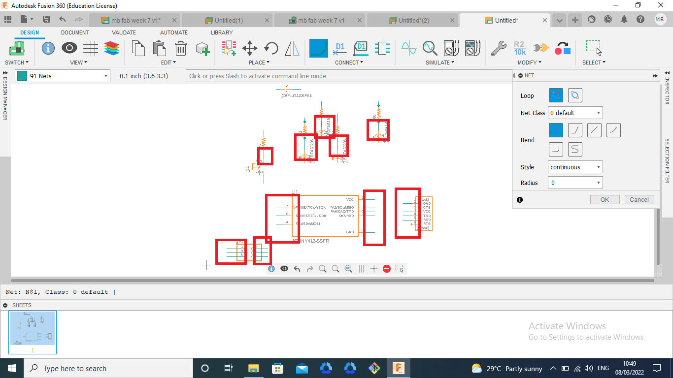
next started the circuit designing take the add parts
 Add ATTiny 412 and Fab library

 Then select the wanted parts using the name and pictuers
Firts I select the ATTiny 412
Then select the wanted parts using the name and pictuers
Firts I select the ATTiny 412

 Then I selected the switch on fab library

 Next selected the LED I connect with three LED

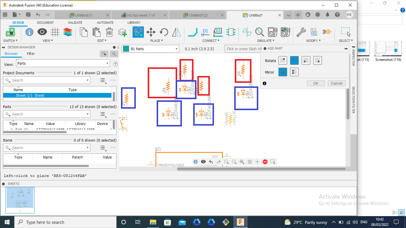 Then select with resistors and capacitor

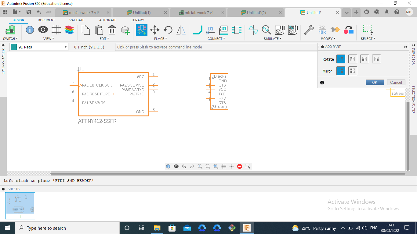
Then I selected in 6 pin header and open it

 Then selected the 2*3 SMD pins
 Next I take the capaciter

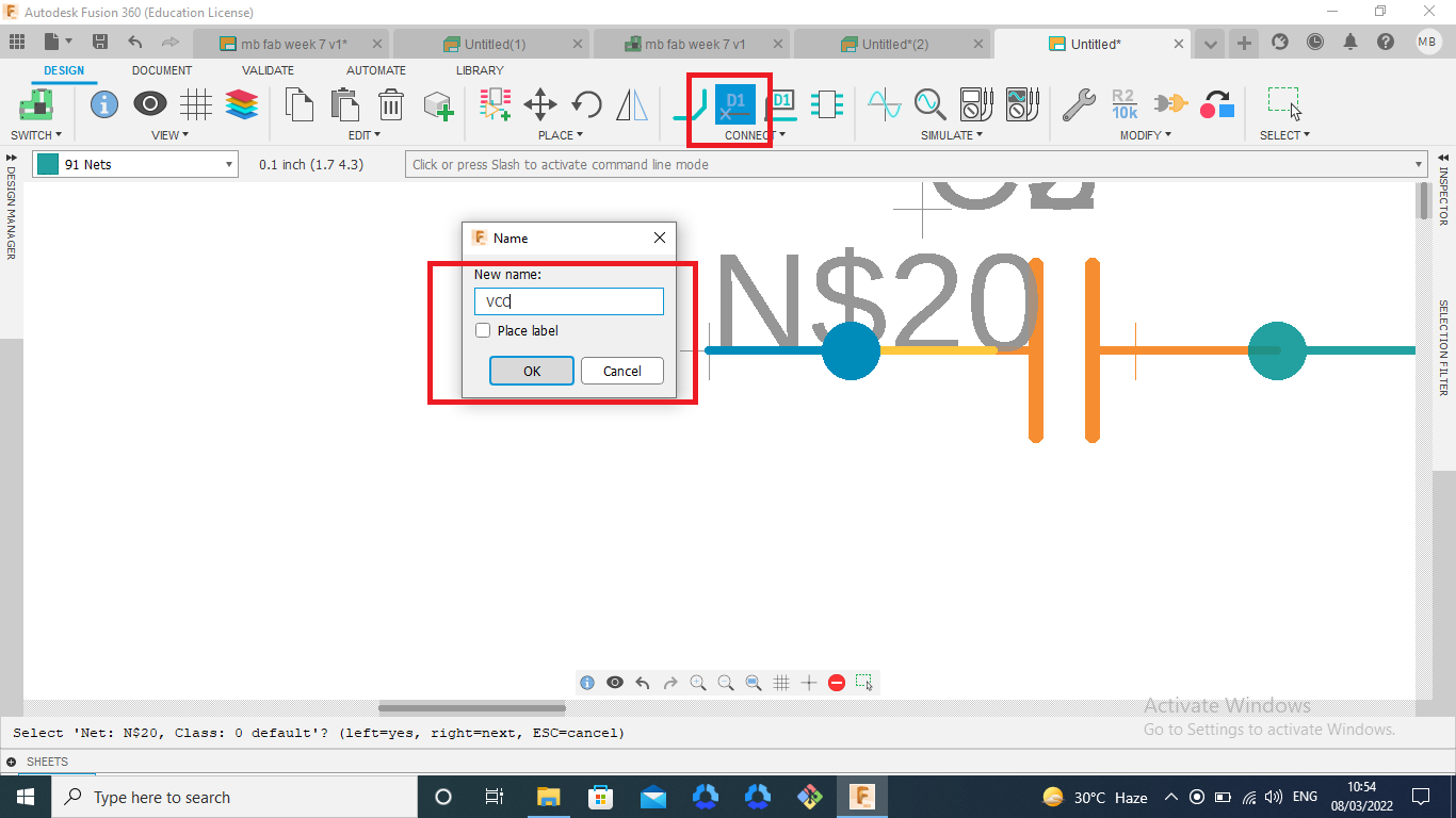
The lines are connected in the possitions

Then add the names in all points for the circuit connections
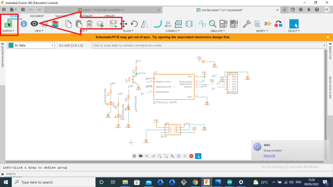
 This button is to switch the screen in pcb circuit mode
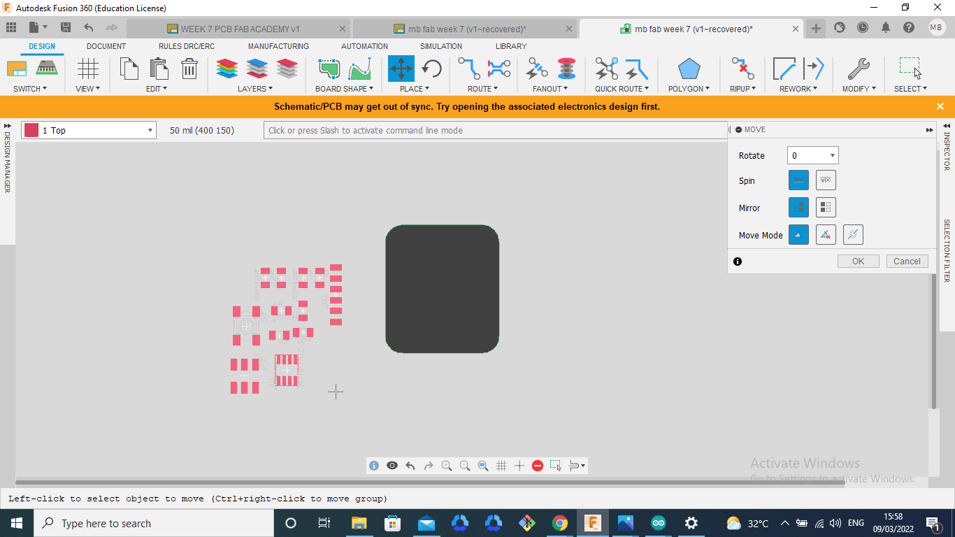
 Then I arrenged the circuit in the possitions

Then next selected in the Drc tab I start to arrange the Drc tab in this tab is used to arrange the milling prosses


I arranged this Drc


Then next I take to draw the routs connecting, this methodes are used


This is the circuit connection rout gets
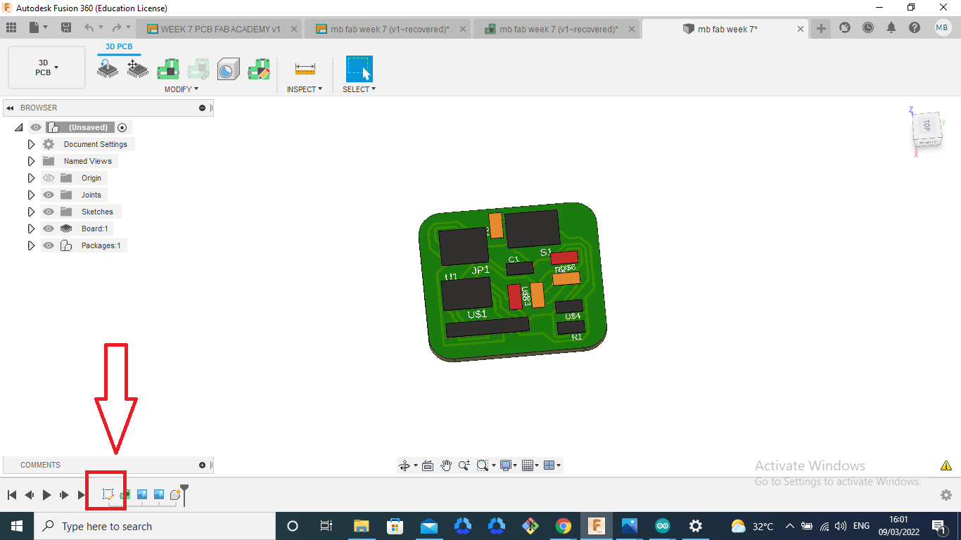
 Then next arrange the PCB boarder then I open the 3D design

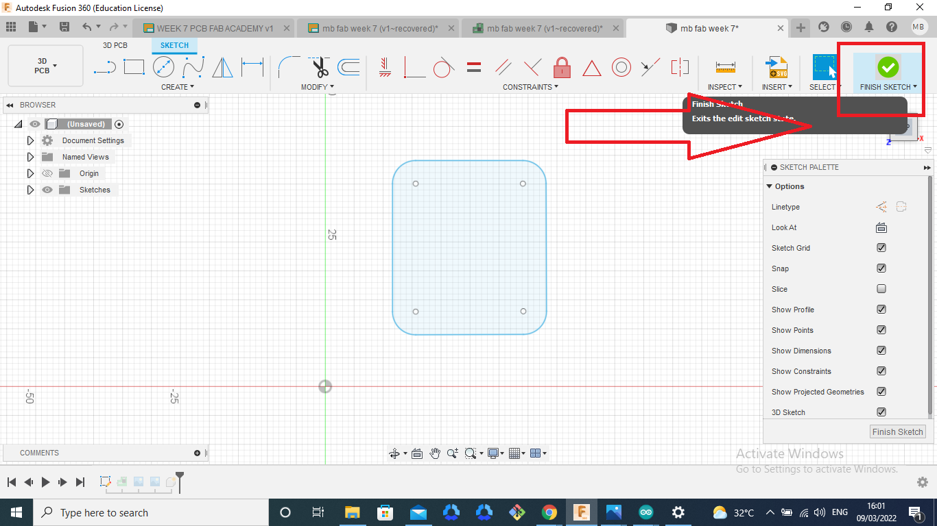
 Then selecte the scketch and arrange the size of boarde

Then Draw and arranged the scketch

This is the final result
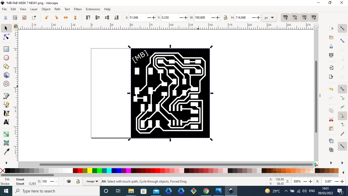
After that I Add a simpol in the PCB using the inkscap
Then start my PCB milling prosses
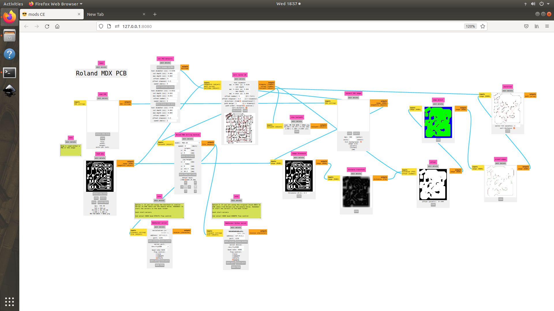

This is the photos in the modes
Milling prosses is start
 The milling is also completed ,after that I take it


This is the final result
 I thake the componens and solder it This is the final result
Then after that I started the programming
 I coonected the jumper wire with my UPDI programmer
 I programmed it using arduio software this is the serial print final result
All Files Download here. Download