9. Embedded Programming
Objectives
- Read the data sheet for your microcontroller.
- Use your programmer to program your board to do something
- Extra credit: try other progrmming languages and development environments
Group Assignment Group Assignment page
- Eompare the performance and development workflows for other architectures.
The Nineth week’s class of my fab academy life took place and the professor Neil class started as usual,this week assignmend as khown as Embedded Programming
Group assignment.
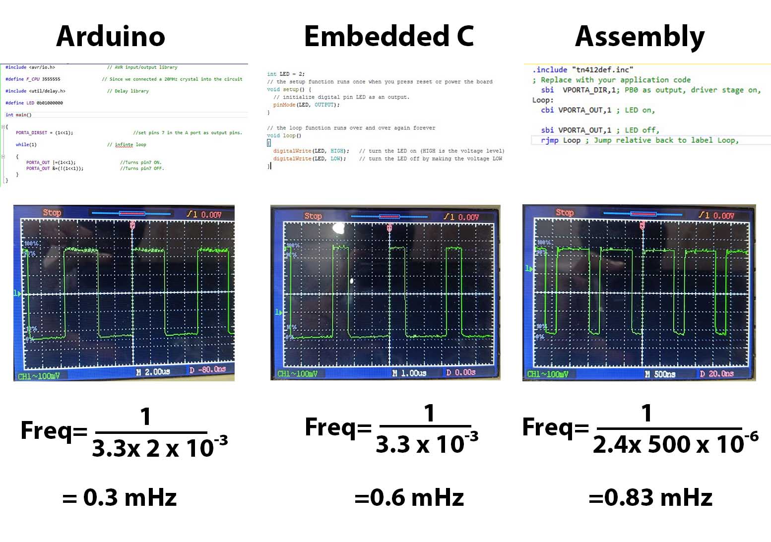
We found the speed of different programming languages and IDEs.
For that programs code for blinking LED with 0 clock cycle gap in Arduino, Embedded C and Assembly language.
Instead of LED pin, we give a pin of RXD.
And we checked the signal using Digital Oscilloscope.
The codes are given below.
int Pin_num = 2 ; // It is the pin of RXD

void setup() {

  // initialize digital pin Pin_num as an output

pinMode(Pin_num, OUTPUT);

}

// the loop function runs over and over again forever

void loop() {

digitalWrite(Pin_num, HIGH);   // turn the LED on (HIGH is the voltage level

digitalWrite(Pin_num, LOW);    // turn the LED off by making the voltage LOW
}
include <avr/io.h>                    // AVR input/output library.

define F_CPU 3555555                // Since we connected a 20MHz crystal into the circuit.

include <util/delay.h>                // Delay library.

define LED 0b01000000.

int main().

{

  PORTA_DIRSET = (1<<6);                       //set pins 7 in the A port as output pins.

  while(1)                           // infinte loop.

  {

    PORTA_OUT |=(1<<6);                 //Turns pin7 ON.

    PORTA_OUT &=(!(1<<6));              //Turns pin7 OFF.

  }

}
include “tn412def.inc”;
Replace with your application code
sbi VPORTA_DIR,7; PB0 as output, driver stage on,
Loop:
cbi VPORTA_OUT,7 ;
sbi VPORTA_OUT,7 ;
rjmp Loop ;

Nucleo
We tried to program Nucleo board.
Steps are given below.
Open Arduino IDE, Go to File → Preference→ Additional Boards Managers URLs, paste the code below
https://github.com/stm32duino/BoardManagerFiles/raw/main/package_stmicroelectronics_index.json Go to Tools→ Board→ Board manager and install STM32 MCU based boards. Go to Tools→ Board→ STM32 boards groups and select Nucleo-64 Go to Tools→ Board part number and select Nucleo F303RE Connect Nucleo F303RE through USB port. Go to Tools → Port and select serial port Write code to blink LED. (Pin 13 is the pin connected to LED)
define LED 13

void setup() {

// initialize digital pin LED_BUILTIN as an output.

pinMode(LED, OUTPUT);

}

// the loop function runs over and over again forever

void loop() {

digitalWrite(LED, HIGH);   // turn the LED on (HIGH is the voltage level)

delay(1000);                       // wait for a second

digitalWrite(LED, LOW);    // turn the LED off by making the voltage LOW

delay(1000);                       // wait for a second
Click on Upload button.
What is Embedded System
An embedded system is a combination of computer hardware and software designed for a specific function. Embedded systems may also function within a larger system. The systems can be programmable or have a fixed functionality. Industrial machines, consumer electronics, agricultural and processing industry devices, automobiles, medical equipment, cameras, digital watches, household appliances, airplanes, vending machines and toys, as well as mobile devices, are possible locations for an embedded system.
While embedded systems are computing systems, they can range from having no user interface (UI) – for example, on devices designed to perform a single task – to complex graphical user interfaces (GUIs), such as in mobile devices. User interfaces can include buttons, LEDs (light-emitting diodes) and touchscreen sensing. Some systems use remote user interfaces as well.
MarketsandMarkets, a business-to-business (B2B) research firm, predicted that the embedded market will be worth $116.2 billion by 2025. Chip manufacturers for embedded systems include many well-known technology companies, such as Apple, IBM, Intel and Texas Instruments. The expected growth is partially due to the continued investment in artificial intelligence (AI), mobile computing and the need for chips designed for high-level processing.
Reading the data sheet
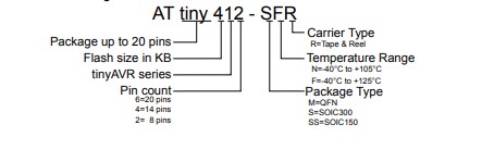
We are using ATtiny 412 microcontroller in our board that made in electronics design week. so the ATtiny 412 some main dates are there
Device Designations
 Block diagram and Pinout diagram
 Instruction set summary
 Supply characteristics

Embedded programing
I know that Arduino is the easiest way to programming, so I started with embedded programming in Arduino IDE,then open the arduino and I started the programming with ATtiny412 board at the board I make to Electronics Design week
This is my board

Let’s start the programming
- Add MegaTinyCore through the Arduino IDE’s board manager.
- Connect the board through UPDI.
- Select chip and port in the Tool menu.
- Write code in Arduino IDE.
- Click on the Upload button.
code
int LED_1 = 0;'

// the setup function runs once when you press reset or power the board

void setup() {

  // initialize digital pin LED_1 as an output.

  pinMode(LED_1, OUTPUT);

}

// the loop function runs over and over again forever

void loop() {

  digitalWrite(LED_1, HIGH);   // turn the LED on (HIGH is the voltage level)

  delay(1000);                       // wait for a second

  digitalWrite(LED_1, LOW);    // turn the LED off by making the voltage LOW

  delay(1000);                       // wait for a second

}
this is the result
###Microchip Studio Programming
What is Microchip Studio ?
Microchip Studio is an Integrated Development Environment (IDE) for developing and debugging AVR® and SAM microcontroller applications. It merges all of the great features and functionality of Atmel Studio into Microchip’s well-supported portfolio of development tools to give you a seamless and easy-to-use environment for writing, building and debugging your applications written in C/C++ or assembly code. Microchip Studio can also import your Arduino® sketches as C++ projects to provide you with a simple transition path from makerspace to marketplace.
I Downlode and open the Microchip Studio
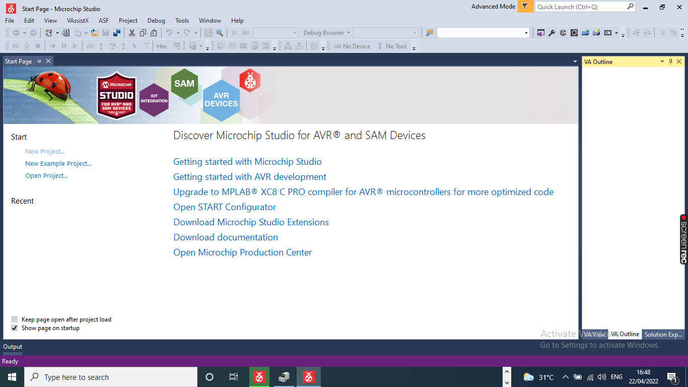 select the New project and click C/C++ button


click the ATtiny 412 tab

after open the new screen select the tools block
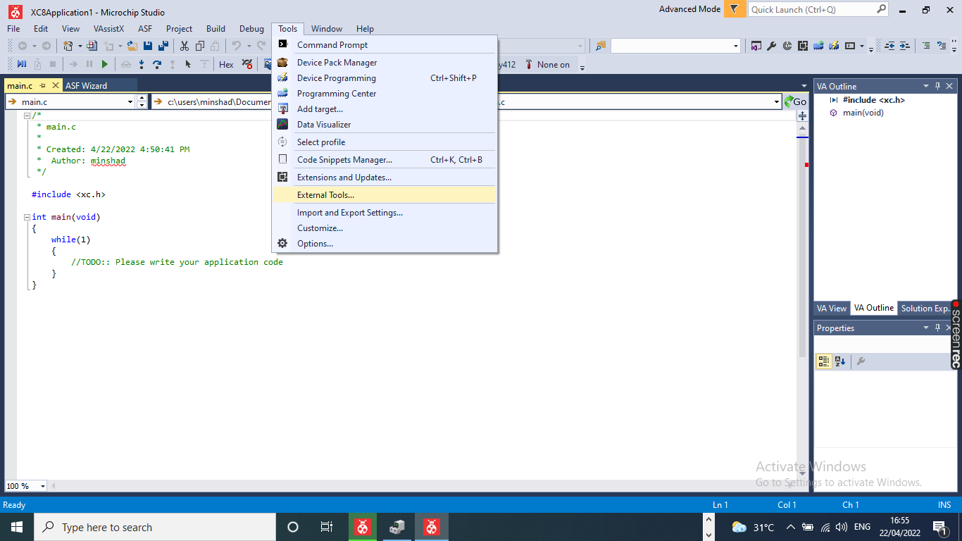
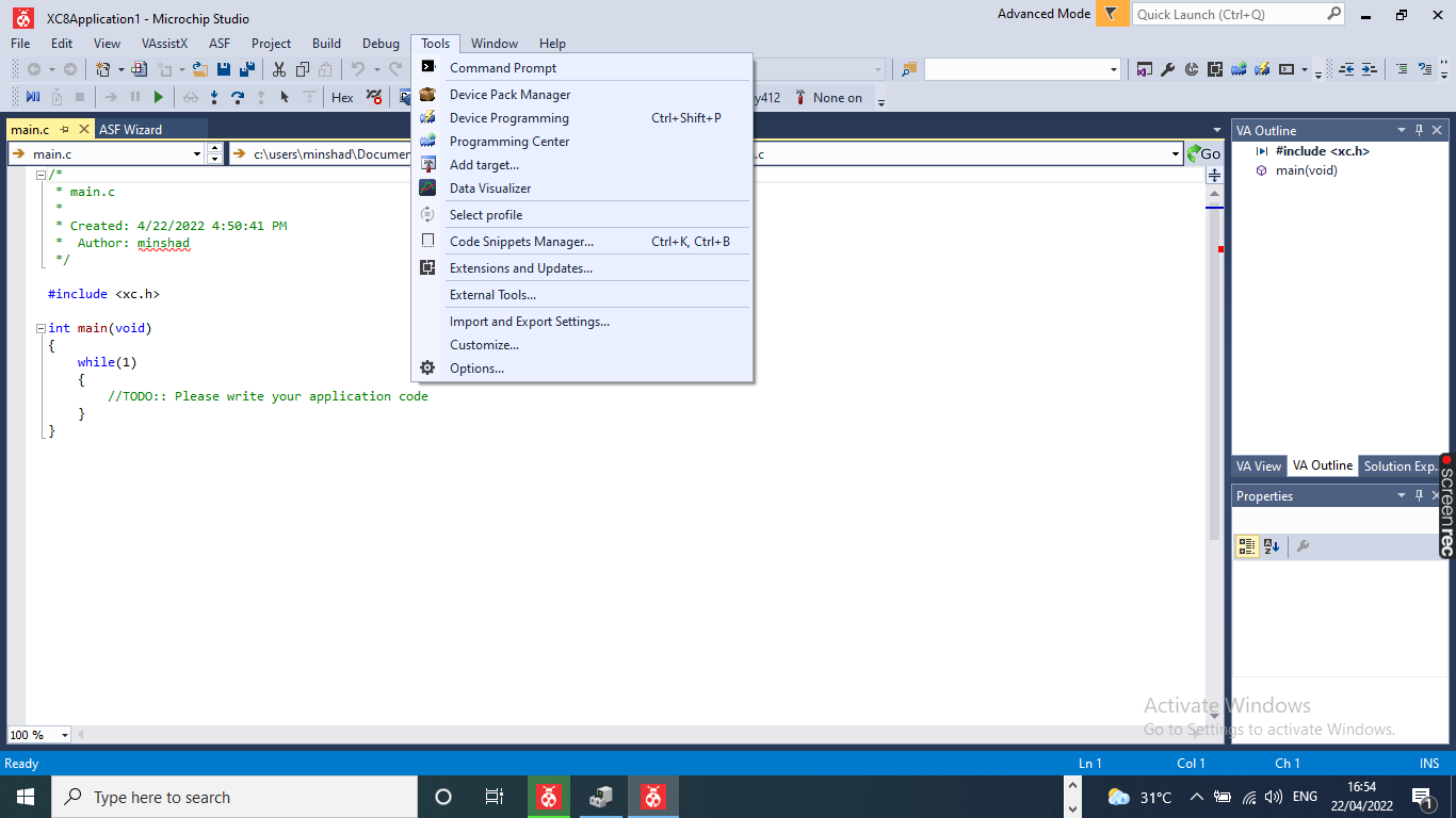 click the External Tools
 select thet
Tittle: updi foe At Tiny
select thet
Tittle: updi foe At Tiny
 Command : Select the file
 Arguments : Select arguments
 Initial director : S[TargetDir]
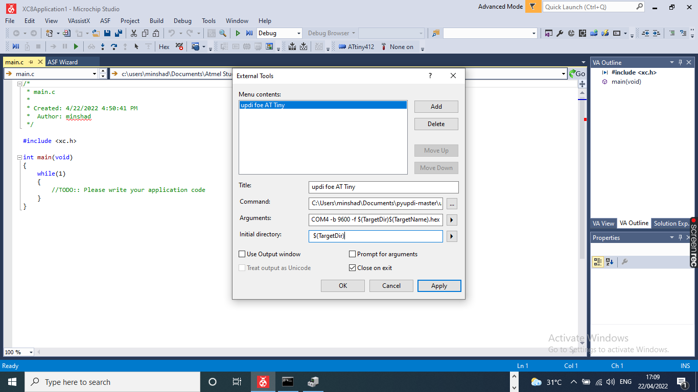 click Apply button
 View the tab updi foe AT Tiny
 select the programming
this is I used codes
int LED_1 = 0;'

// the setup function runs once when you press reset or power the board

void setup() {

  // initialize digital pin LED_1 as an output.

  pinMode(LED_1, OUTPUT);

}

// the loop function runs over and over again forever

void loop() {

  digitalWrite(LED_1, HIGH);   // turn the LED on (HIGH is the voltage level)

  delay(1000);                       // wait for a second

  digitalWrite(LED_1, LOW);    // turn the LED off by making the voltage LOW

  delay(1000);                       // wait for a second

}
 click Build Selection
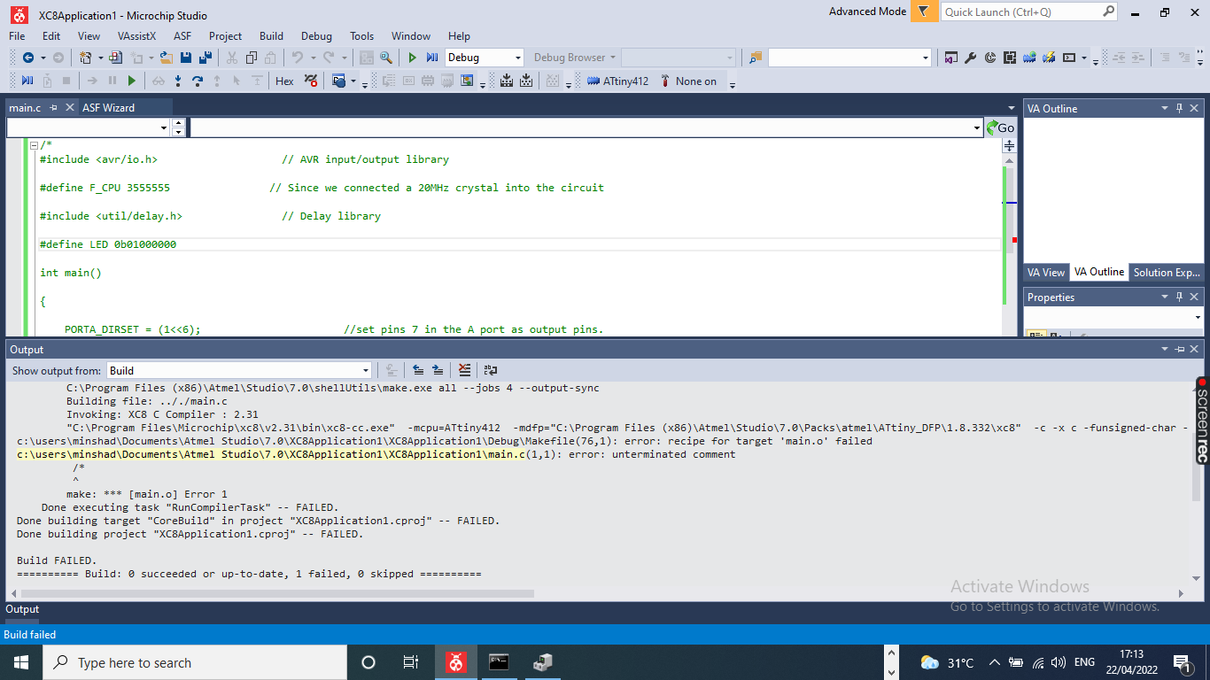 program uploding done

This is the final result
All Files Download here Download