10. Output Devices (Indonesia group)
This is group assignment page of Output Devices (Indonesia Student) :
Group assignment:
- measure the power consumption of an output device
Measure the power consumption of an output device
This week we will conduct electrical measurements when running the output device. From this measurement we will know the load that occurs on the MCU. The MCU has a maximum load (current) that can be passed, if the current that passes exceeds the allowable it will cause damage to the Microcontroller. This measurement is to determine the electrical characteristics used when the MCU operates the output device.
Equipments
To perform measurements on the microcontroller device that drives the output device, several devices are needed, including:
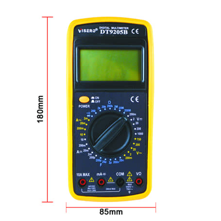
- Multimeter
- Oscilloscope
- Logic Analyzer
- etc.
But, in this task we will only measure the voltage and current used for the running output device, so we will simply use a Multimeter. Also we need a Adjustable Power Supply for generating electricity which will be used as a source of output devices
Output Devices
The output device we will be testing is a stepper motor. This motor will be run by the MCU through the driver and the required voltage and current will be measured when using a load or without a load.

The circuit :

The first step in running a stepper motor is to limit the current that will pass through the driver. To check the amount of current by measuring between the screw on the driver and ground. The measured voltage value is formulated by: Current Limit = Vref × 2
The current limit can be seen in the motor datasheet

on this stepper motor has a current limit of 1.3A so for tips we can use 70-80% of the maximum current capacity. we set the rated voltage current to about 0.5V

Test the voltage
When the stepper rotates we want to know how much voltage can be used to rotate the stepper motor.
Code used:
// Define stepper motor connections and steps per revolution:
#define dirPin 1
#define stepPin 0
#define stepsPerRevolution 200

void setup() {
  // Declare pins as output:
  pinMode(stepPin, OUTPUT);
  pinMode(dirPin, OUTPUT);
}

void loop() {
  // Set the spinning direction clockwise:
  digitalWrite(dirPin, HIGH);

  // Spin the stepper motor 1 revolution slowly:
  for (int i = 0; i < stepsPerRevolution; i++) {
    // These four lines result in 1 step:
    digitalWrite(stepPin, HIGH);
    delayMicroseconds(2000);
    digitalWrite(stepPin, LOW);
    delayMicroseconds(2000);
  }

  delay(1000);

  // Set the spinning direction counterclockwise:
  digitalWrite(dirPin, LOW);

  // Spin the stepper motor 1 revolution quickly:
  for (int i = 0; i < stepsPerRevolution; i++) {
    // These four lines result in 1 step:
    digitalWrite(stepPin, HIGH);
    delayMicroseconds(1000);
    digitalWrite(stepPin, LOW);
    delayMicroseconds(1000);
  }

  delay(1000);

  // Set the spinning direction clockwise:
  digitalWrite(dirPin, HIGH);

  // Spin the stepper motor 5 revolutions fast:
  for (int i = 0; i < 5 * stepsPerRevolution; i++) {
    // These four lines result in 1 step:
    digitalWrite(stepPin, HIGH);
    delayMicroseconds(500);
    digitalWrite(stepPin, LOW);
    delayMicroseconds(500);
  }

  delay(1000);

  // Set the spinning direction counterclockwise:
  digitalWrite(dirPin, LOW);

  //Spin the stepper motor 5 revolutions fast:
  for (int i = 0; i < 5 * stepsPerRevolution; i++) {
    // These four lines result in 1 step:
    digitalWrite(stepPin, HIGH);
    delayMicroseconds(500);
    digitalWrite(stepPin, LOW);
    delayMicroseconds(500);
  }

  delay(1000);
}
To find out the value of the voltage used, we directly read from the display of Adjustable Power Supply.
Voltage when the motor starts to rotate occurs at a voltage of 9V. Passing current is set at Vref 0.5V
Current Test
In this task we use an LED light to measure the required current value. LEDs use Charlieplexing boards by programming to light one, two, or many LEDs that light up alternately. then the current is measured.


The code :
int A = 15;
int B = 14;
int C = 2;
int D = 0;
int E = 1;

void setup() {
  pinMode(A, OUTPUT);
  pinMode(B, OUTPUT);
  pinMode(C, OUTPUT);
    pinMode(D, OUTPUT);
      pinMode(E, OUTPUT);
}

// the loop function runs over and over again forever
void loop() {
  digitalWrite(A, HIGH);   // turn the LED on (HIGH is the voltage level)
  digitalWrite(B, LOW);    // turn the LED off by making the voltage LOW
  digitalWrite(C, LOW);
  digitalWrite(D, LOW);
  digitalWrite(E, LOW);
  delay(1000);                       // wait for a second

  digitalWrite(A, HIGH);   // turn the LED on (HIGH is the voltage level)
  digitalWrite(B, HIGH);    // turn the LED off by making the voltage LOW
  digitalWrite(C, LOW);
  digitalWrite(D, LOW);
  digitalWrite(E, LOW);
  delay(1000);                       // wait for a second

  digitalWrite(A, HIGH);   // turn the LED on (HIGH is the voltage level)
  digitalWrite(B, HIGH);    // turn the LED off by making the voltage LOW
  digitalWrite(C, HIGH);
  digitalWrite(D, LOW);
  digitalWrite(E, LOW);
  delay(1000);

  digitalWrite(A, HIGH);   // turn the LED on (HIGH is the voltage level)
  digitalWrite(B, HIGH);    // turn the LED off by making the voltage LOW
  digitalWrite(C, HIGH);
  digitalWrite(D, HIGH);
  digitalWrite(E, LOW);
  delay(1000);

  digitalWrite(A, HIGH);   // turn the LED on (HIGH is the voltage level)
  digitalWrite(B, HIGH);    // turn the LED off by making the voltage LOW
  digitalWrite(C, HIGH);
  digitalWrite(D, HIGH);
  digitalWrite(E, HIGH);
  delay(1000);
}
The test result
when the led is on, the electric current is about 0.03 A When several LEDs are lit at the same time, the current passing through also increases. Like when 6 leds are on then the current shows about 0.06A.