Computer Controlled Cutting
Group Project
the group project for this week was to understand how changing the seting of the laser cuter changes the quality of the cuts. the seting that we can change are the speed of the laser, the power of the laser and the fercency of laser pulse. those setting change how the laser cuts and engraves meteral. the thing that we were looking at to see the efect of the settings is kurf. the kurf is the amount of meteral removed by the laser when its cuting. to test the kurf we cut out a bunch of squares and meshured the squars and compared that to the size we intended.Vinyl Cutting
part of the asinement for this week was to create a team logo, vinyl cut it and then apply it to a surface. This is the logo we made that I applied to my notebook.
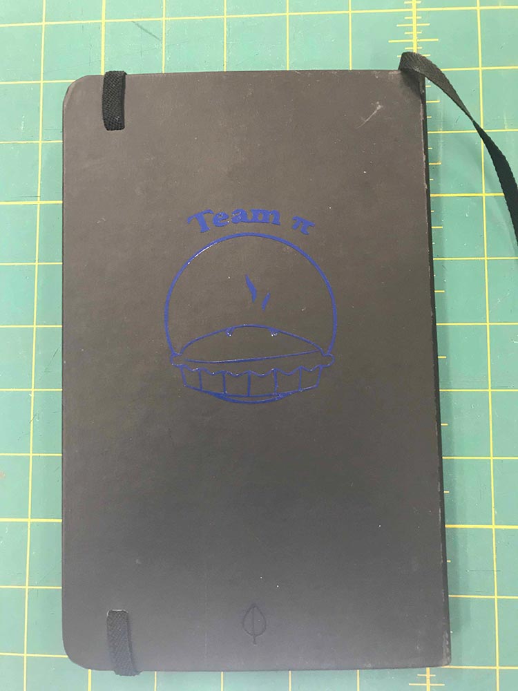
to get this vinyl cut you first have to generate the design then we put that design into the program "sure cuts a lot". After that we just ran the vinyl cutter with our design. This cuts the vinyl into our design then we have to remove all the unwanted parts this is called "weeding". The image below on the left is what my decal looked like part way through the weeding process. After you finish the wedding you apply the application tape to the vinyl cutout and then remove the backing from the vinyl then you apply the vinel to the intended surface.the image below on the right is what my vinyl looked like before application.
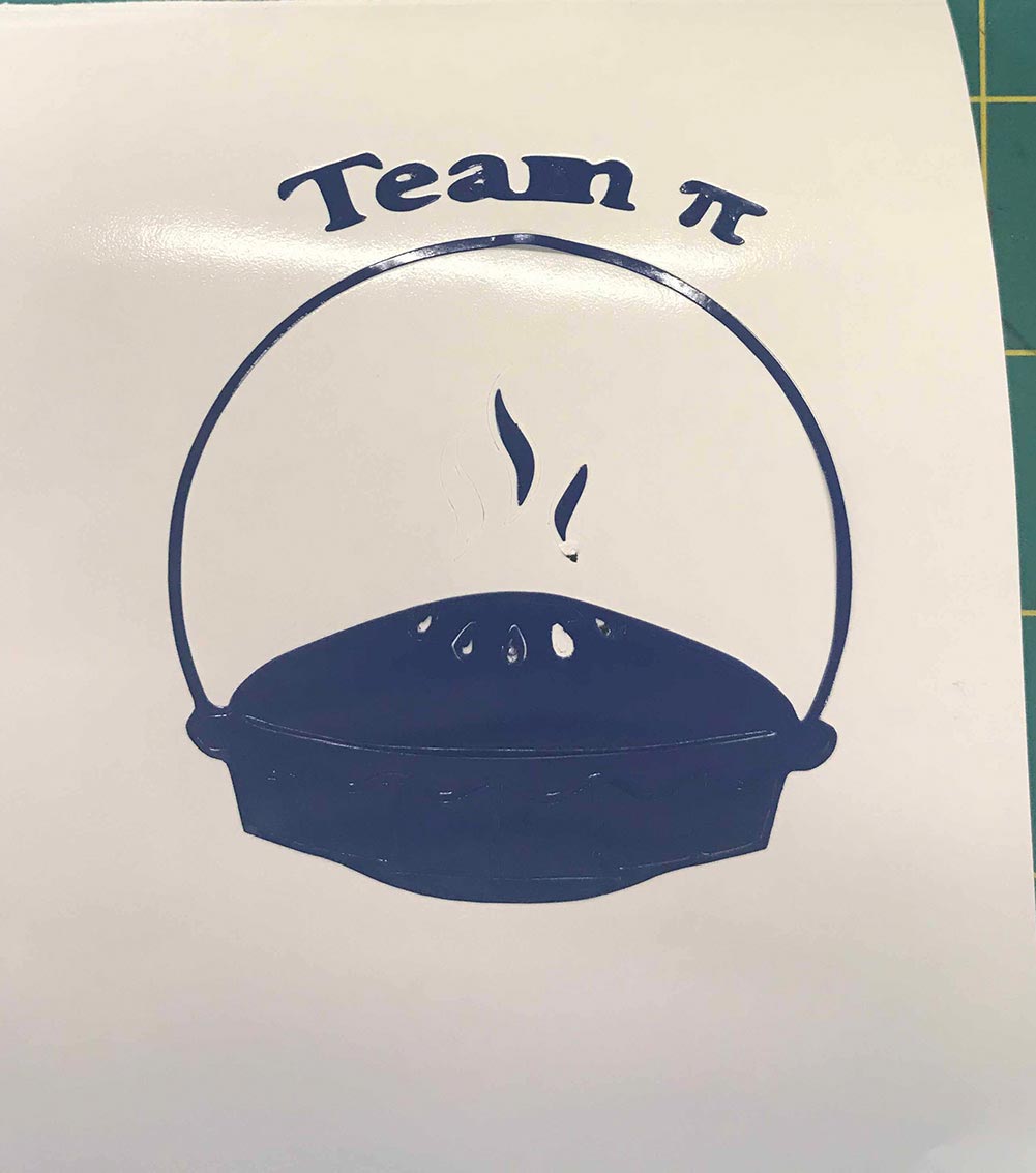 |
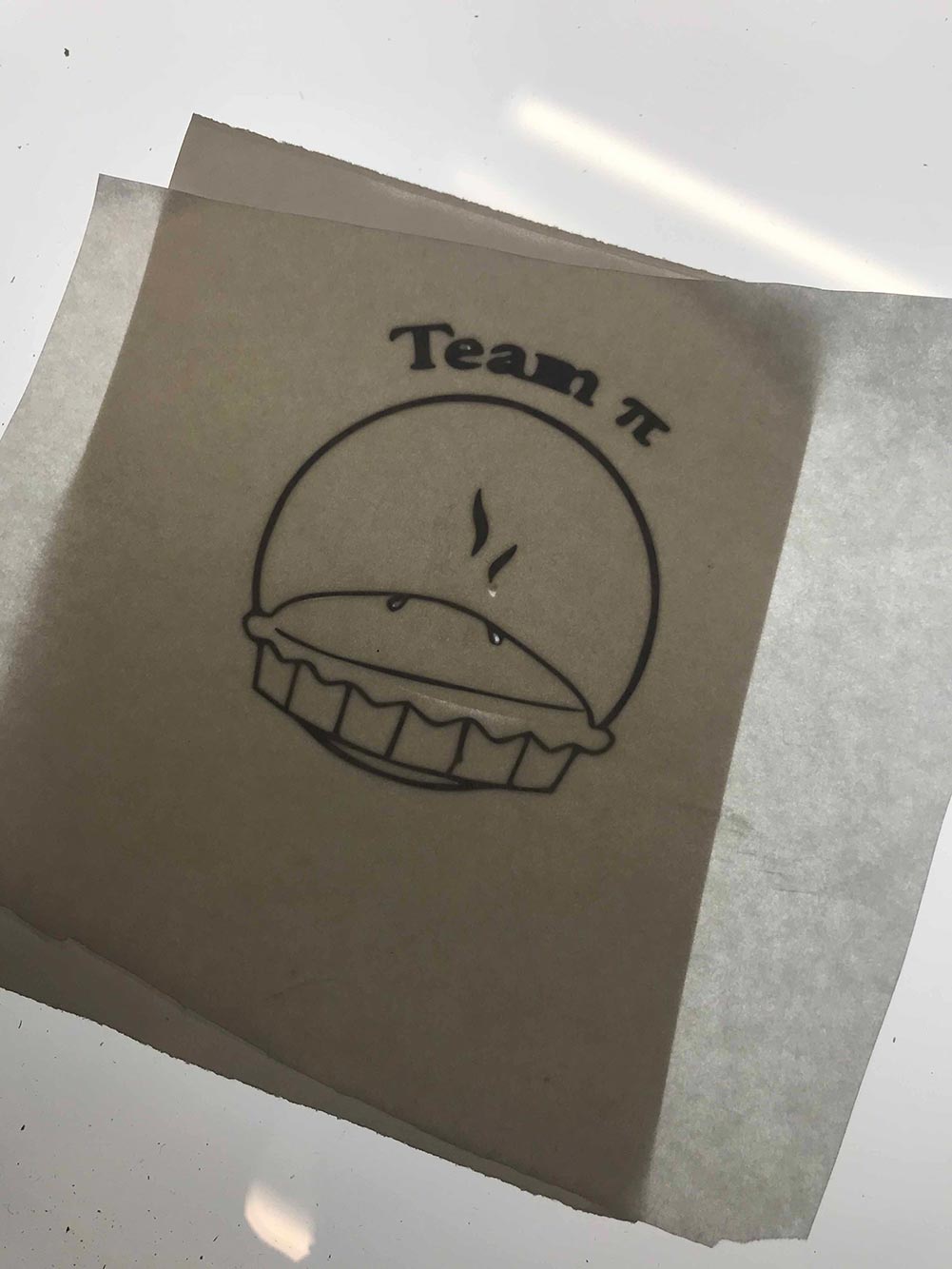 |
the first image is what my notebook looked like after applying the vinyl
Parametric design
Parametric design is when you make a design off a varible so that it is easaly scaled.
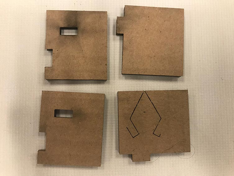
Before I started my designing I worked on getting the right setting for laser cutting cardboard on our machine. and I also wanted to make sure that I had the curf right so that fusion 360 could create the correct image for processing. To do this I created the little test fit design below. I selected the wrong print file so I stopped the laser and started over. That's why one of my pieces has a different look.
for the parametric design assignment I decided to make a Dice Tower. when I made my design I started with the side panel. I used an already created side panel as the template for the opposite side panel. using those side panels bottoms as a reference I cut the needed holes on the base plate to make the sides fit. I then created the front and back of the tower by doing the same process except that for the front I cut out an arch for the dice to come out of. using the front and the back as templates like the sides I then made the holes on the bottom plate to fit the front and back. After that I made the stop and projected its bottom onto the base to remove the needed material. The image below is what I had after this step.
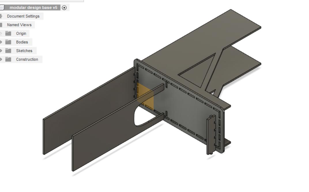
I then added tabs to the back panel which was projected onto the front panel. The next thing that I did using the joint tool I assembled the tower using the base plate as the guide. because I had added tabs to the front and back there was overlap between the panels. I used the extrude tool to remove the overly in such a way that the tower would go together. I then created the slots on the original side sketch needed to have an internal ledge . Using the joint tool again I put the ledges on the inside of the tower. this is that image.
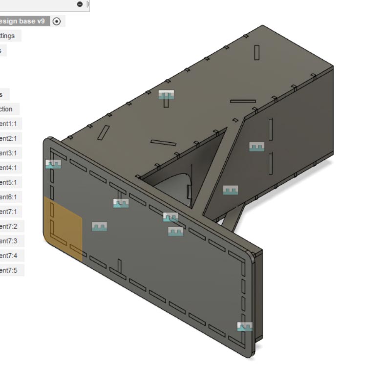
I then did some math so that the ledges would fit into the slots without having any overly. After I was happy with all the parts and their fits I used the joint tool this time the face to point tool to arrange all the pieces on one plane so that it was ready for processing. Here is what that looked like.
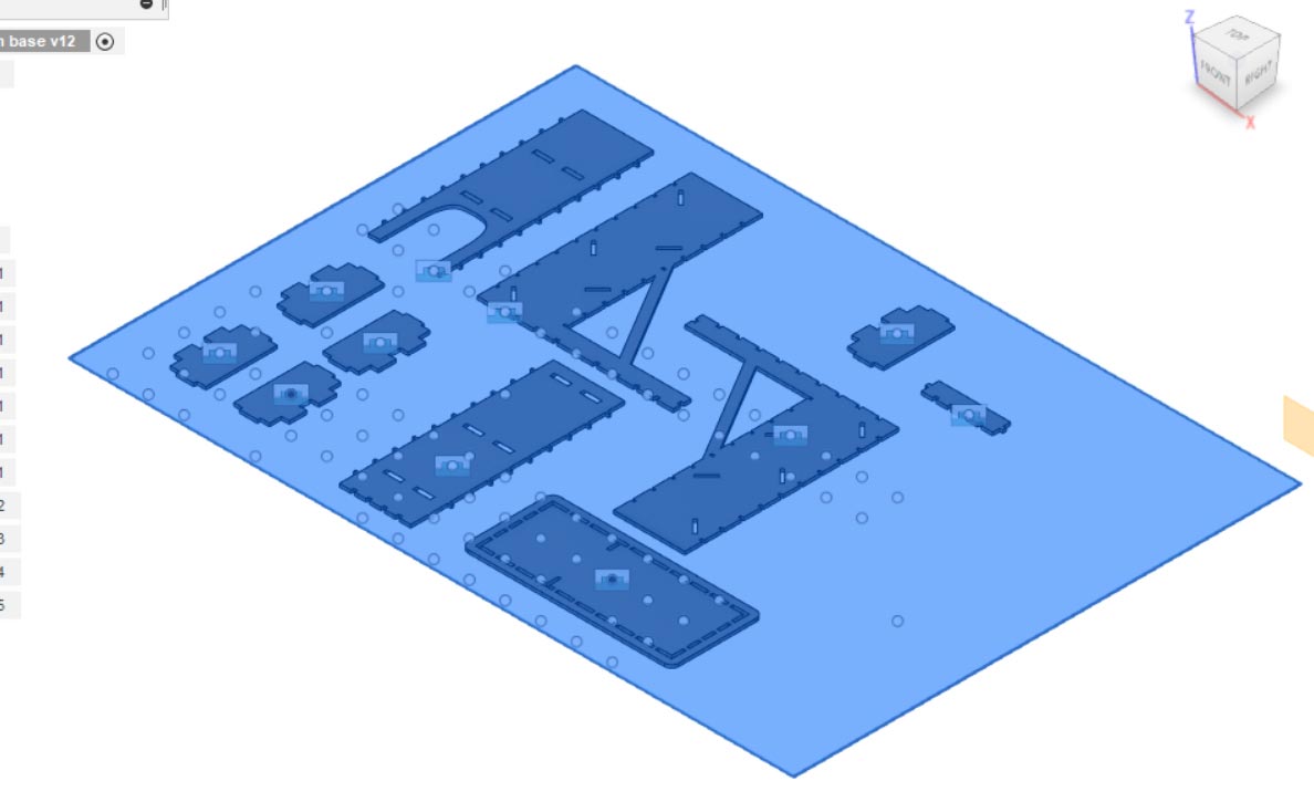
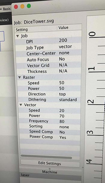
After that I used the manufacture tab of fusion to create the .svg file that was needed to laser cut. I then process that file in the epilogue software so that the laser cut knows what to do. The image below is of the lasters settings.
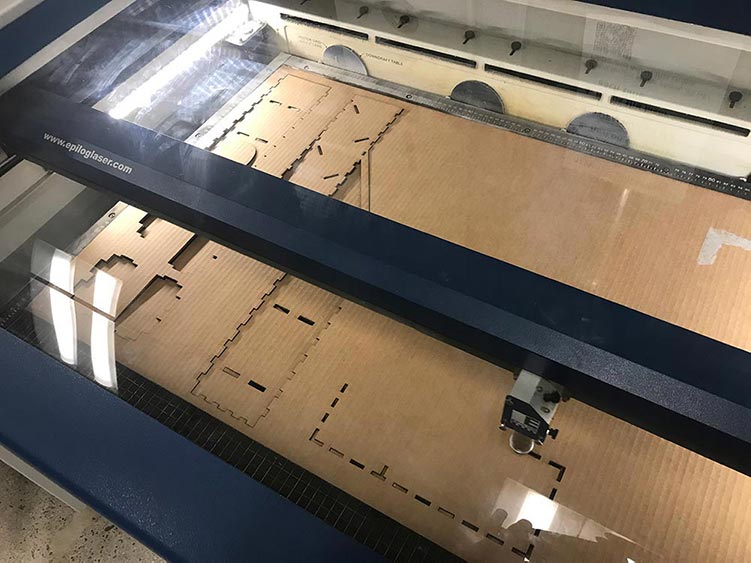
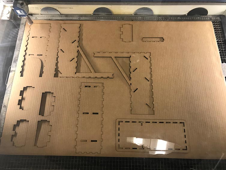
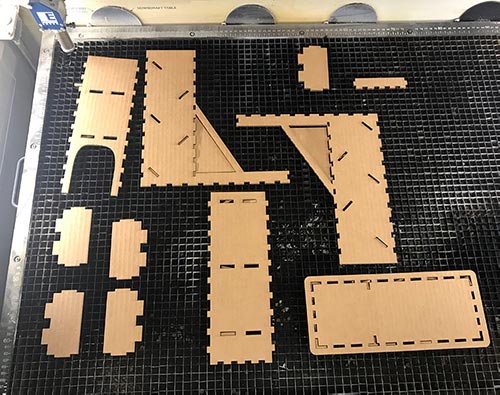
Here are some images of the laser in progress and after removing the unneeded cardboard.
 |
 |
 |
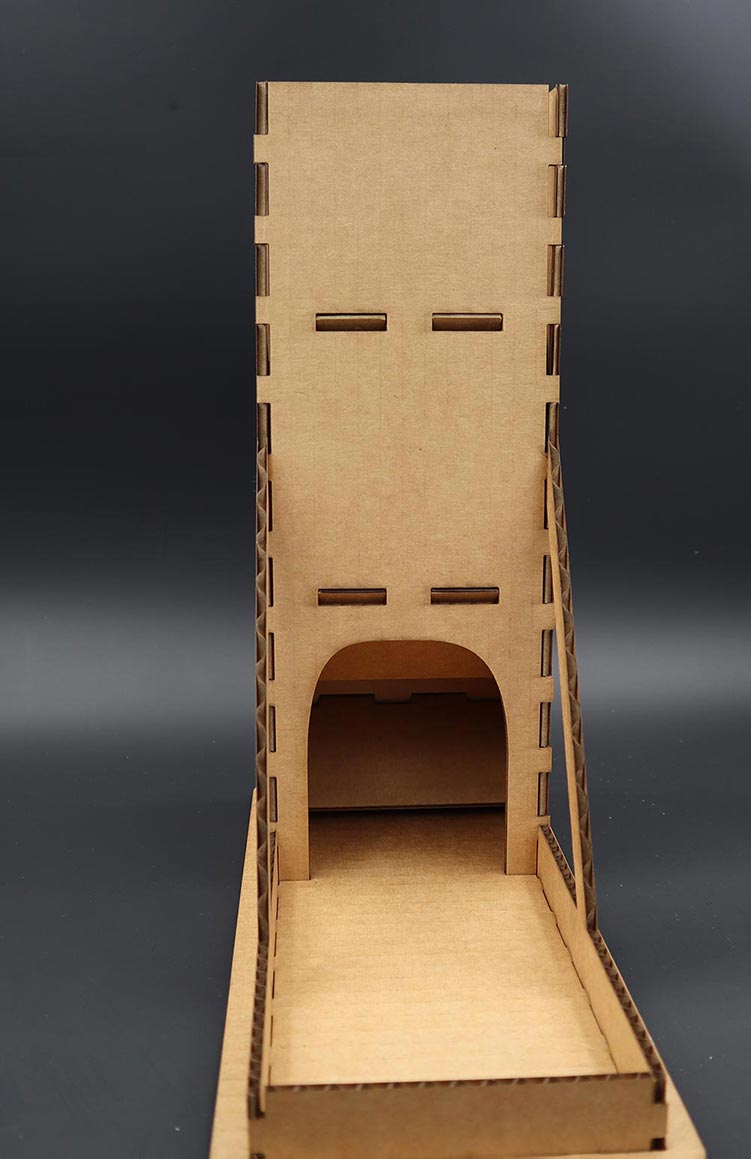
these are some images of the completed dice tower
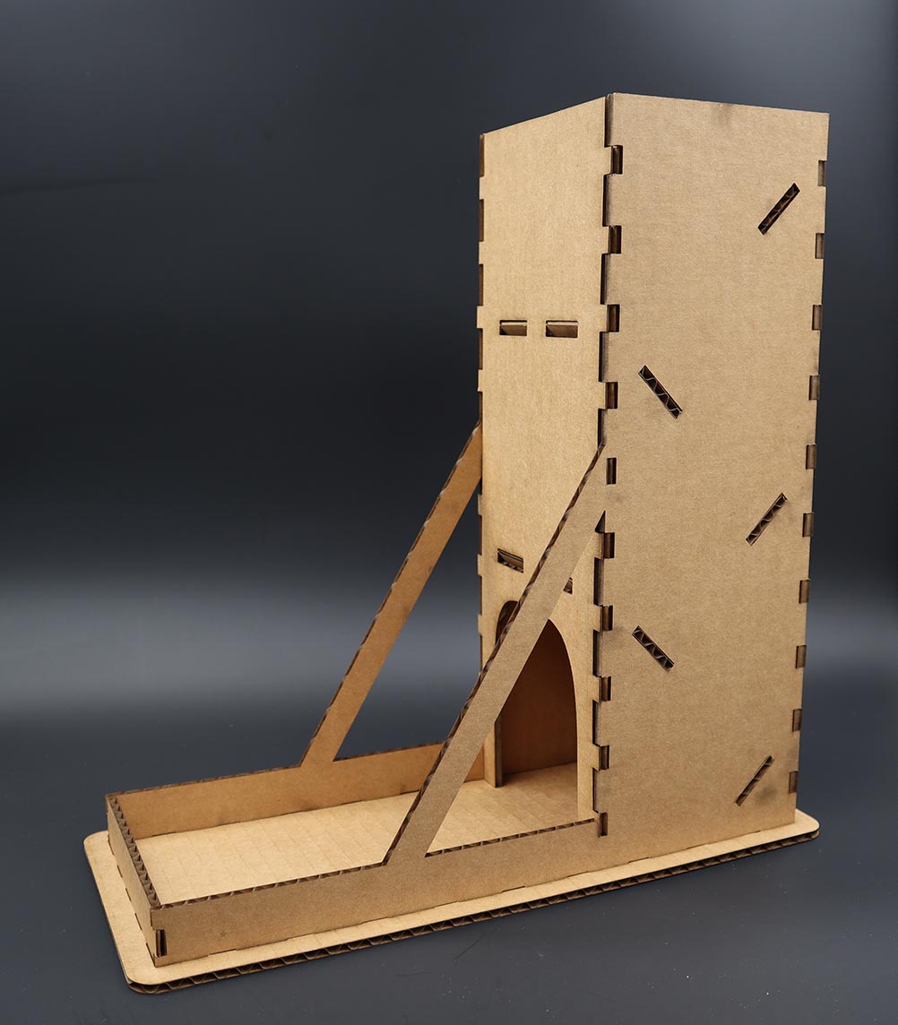
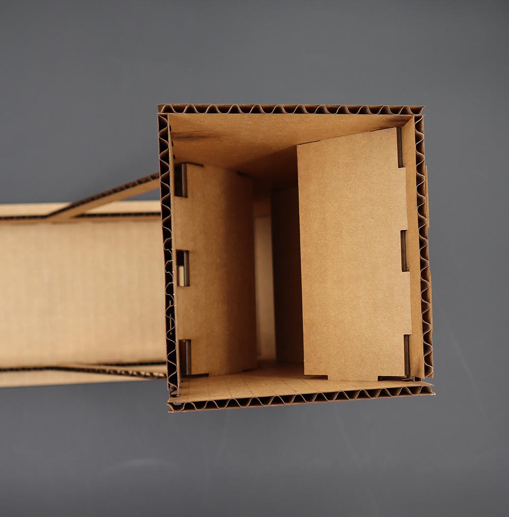
here is a link to my files look in week two for this week's files.
here is the link