3. Computer-Controlled Cutting
Objectives
- Group assignment: characterize your lasercutter's focus, power, speed, rate, kerf, joint clearance and types.
- Cut something on the vinylcutter.
- Design, lasercut and document a parametric construction kit, accounting for the lasercutter kerf which can be assembled in multiple ways.
- Try to include elements which aren't flat.
This week is about computer-controlled cutting, meaning that we get to cut and slice things using digitally-controlled tools such as a laser or vinyl cutter.
This is very much linked with previous week’s class as now, I’ll have no other choice than to use CAD tools to make my design and then export them to the cutting tools.
I’ll have 3 objectives this week.
-
I would like to make a very small electronics circuit using copper tape and a vinyl cutter. I don’t expect very nice results with it but if it works sufficiently well, then it might be an extremely quick way to make some traces without the need to order a PCB or to make it using a CNC or chemical processes. Moreover, that makes it easy to create flexible circuits if I ever need some.
-
Before this, I want to get some experiments using the vinyl cutter by simply cutting some stickers with some logos or customize a t-shirt using heat transfer (spoiler alert: I didn’t make any shirts but maybe in the future)!
-
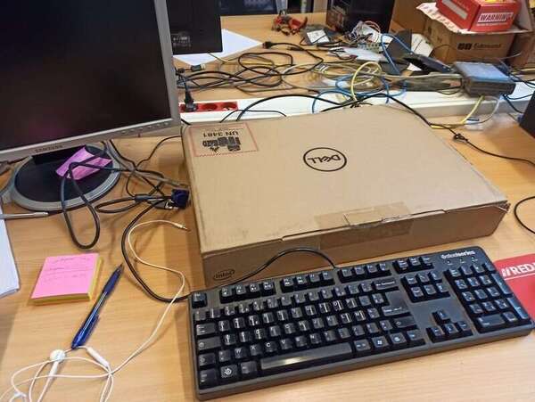
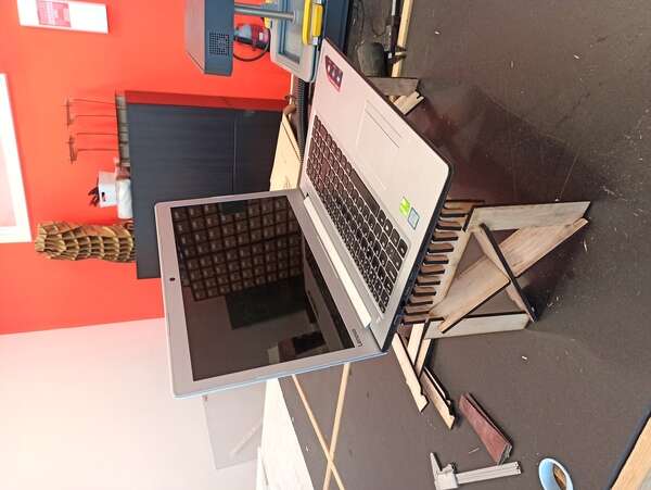
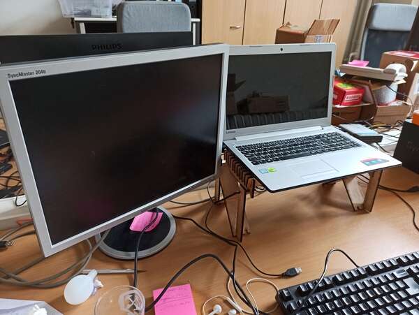
Finally, I have a relatively big desk at work but just like every desk, it gets clumped with all sorts of stuff. My biggest issue is that my laptop rests on a cardboard box (so that it sits at eye level) and sometimes when I need to take notes during online meetings, I don’t have enough room in front of my laptop because of this huge cardboard box. So I want to make a press-fit kit like a small table where I can leave my laptop on and slide my keyboard underneath.
1. Tools
Multiple tools exist to cut things. Some are more expensive, some are easier to use, some a safer but mainly it depends on what you want to do and especially the machines that you have available at your Fablab.
Among these:
Knifes Tools
By knife tools, I mean the tools that use a piece of metal like a knife to cut through paper (in 2D of course). The vinyl cutter is a perfect example of it. At the Fablab ULB, we have the Silhouette Cameo 3 that uses a small blade to cut paper, cardboard or textiles up to 30cm in width and 3 meters long! Cool feature: the blade can be replaced with a pen to make dashed lines and can locate itself on the paper using pattern images.
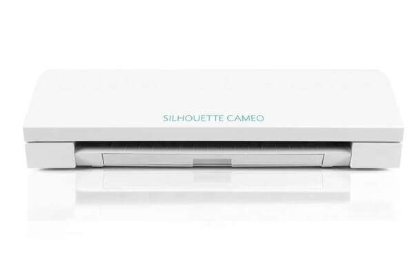
There are multiple other types of knife tools that can punch, roll, shear paper… But those are super expensive and we don’t have these kinds at the ULB.
Some cutters use ultrasonic energy to melt plastic or burn wood at the same time as cutting! I would love to try one of these a day.
Laser cutters
We have a CO2 EPILOG FUSION PRO with a working surface of 30x60cm and that is interfaced with CorelDraw. The CO2 part means that the gain medium is CO2! The medium will change the light frequency of the laser and given that materials don’t absorb all frequencies at the same level, the laser frequency will influence the type of material it can cut.
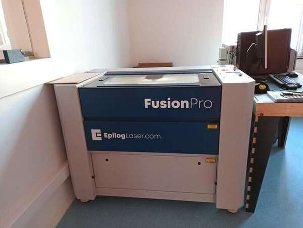
CO2 lasers are cheap and efficient but are limited to cardboard, wood, and acrylic mainly. Fiber lasers can cut metals!
And the rest!
Plasma cutters are for metal cutting by melting the metal (extremely hot plume). Waterjet cutters output water at a supersonic speed that cuts through metal sheets, stones, and almost everything (way more things than a laser cutter) and is mostly used in the industry. Hotwire cutters can be used to make artistic shapes in foam with a heating resistor a voltage on its ends. The result is extremely smooth and the minimum diameter is of the wire itself which can be extremely low.
2. To parametric design!
So to do a cardboard design using the laser cutter, we’ll need to set the width of the slots and their depth. The width depends only on the cardboard thickness (and a margin) but can be therefore set in a parametric manner in the CAD tool (meaning that a simple change of the parameter variable will change the whole design).
CAD tools
Basically, we can use most of the tools described last week. Inkscape for example has multiple extension that can be used to make it more parametric. It’s fairly limited (we need to use clone parts so that they are linked) but still a possibility for laser cutting. We also discussed other possibilities last week like Rhino and the Grasshopper extension.
There are also specifically designed tools for laser cutting, like FlatLab that I will maybe use at the end of the week to design an animal or something.
To complete my objective, I will personally be using FreeCAD (in sketcher workbench mode) that I learned last week, and SolidWorks as I know it well. “Execuc” made a nice module for FreeCAD available on Github that can create interlocking cut parts from a 3D model, as 2D SVG! I will try to use it but I need to understand the basics myself first.
The horse machine whisperer
Getting a design is one thing but then you need to “inject” your design into the cutting machine. Each machine has its drivers so this is one way of doing it. But other tools exist like Deepnest. Deepnest is an open-source software that will optimize the cuts and the parts so waste the least amount of material and time (merging common lines and so on). This also will improve the quality of the final results by avoiding heat warping (distortion in the material due to the heat of the laser) with every subsequent laser pass.
3. Machine setup and characterization
As part of the group assignment, Jason and I had to characterize the laser cutter we were going to use. We wanted to check a few things:
- Check the focus
- Measure kerf
- Play with the power/speed ratio to find the good settings for our material for both cutting and engraving.
For this part, I used plywood found at the lab.
Focus
For the focus, it’s actually quite simple. The Epilog has an automatic focus setting that uses a plunge to measure the material height and adjust the focus. It is however not to be used with soft materials as it will bump into it may leave traces! Hopefully, for us, the length of the waist of our laser cutter is quite long so it’s hard to be really out of focus. Once the focus is done, no need to touch it again for the same material. We couldn’t test it but we suppose that if dramatically out-of-focus, then the power would be more dissipated in the material and it may be better for engraving?
Kerf
To measure the kerf, we just need to cut a square and measure the difference between the expected width and measured width. Since we “lose” half a kerf unit on each laser pass, we lose a full kerf unit per square. To enhance the accuracy of the measurement, we cut 10 squares and placed them together: our result was therefore 10 times more accurate.
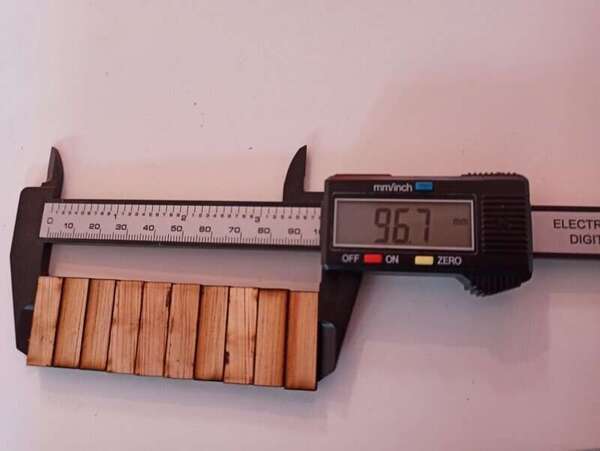
We measured a kerf of 3.3mm for the 10 squares, therefore we have a kerf unit = 0.33mm. It is actually twice what we expected (the Lasersaur that our Lab uses usually has a mean kerf of about 0.17mm) so it’s a good thing we actually measured it before cutting parts of our construction kits.
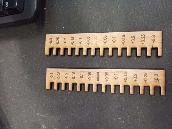
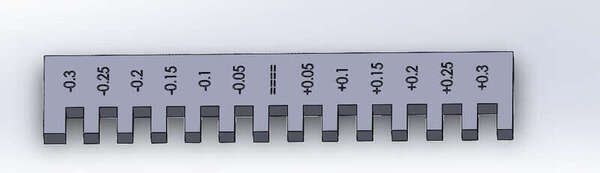
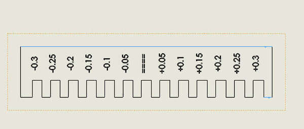
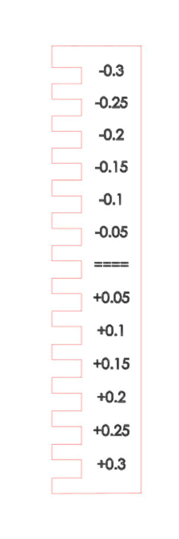
To test some press-fit joints, we made a “comb-like” shape with slots of different sizes. The best fit was for joints with a -0.3mm offset.
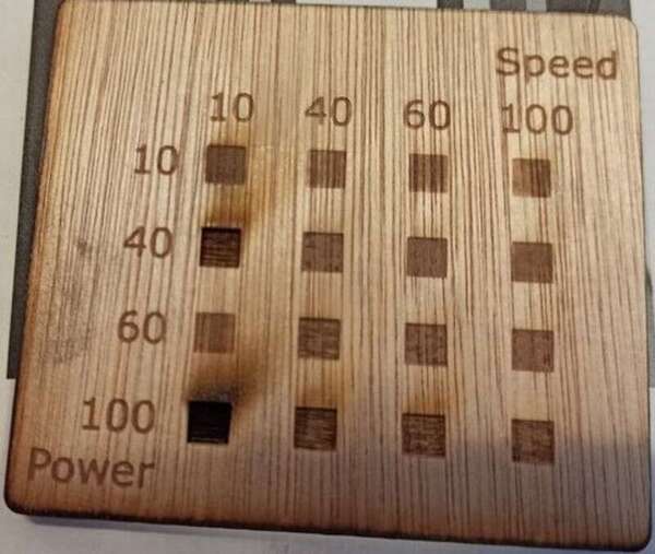
Power and speed
Finally to find the good speed and power ratio for our material, we prepared an SVG file with multiple squares of different colors that we could link to actual parameters in the Epilog software. Sometimes there is no need to reinvent the wheel so we just followed the design of our predecessors but this time with the intent to test it on the Epilog and test the engraving capabilities.
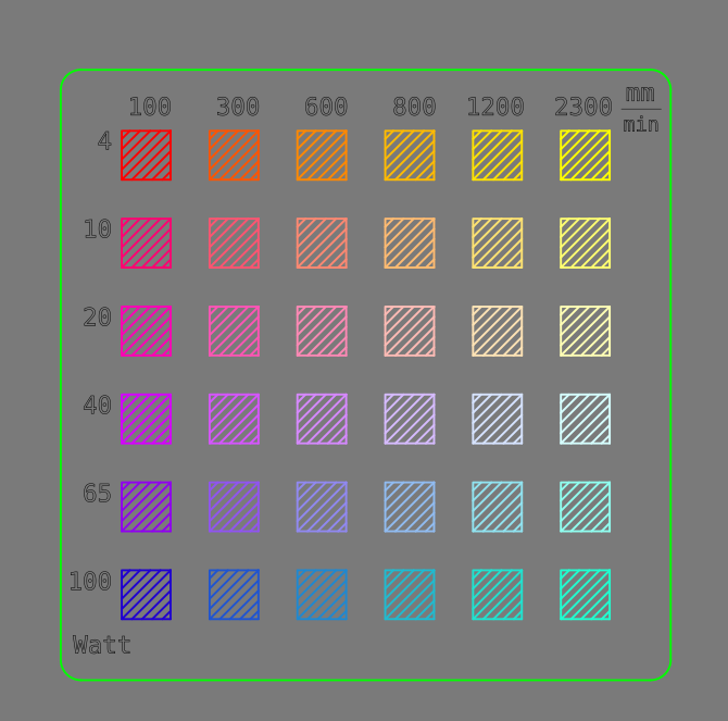
What we could observe is that, as expected, the ratio of speed and power outputs the same result. It is quite logical as the slower the pass is, the more power is delivered to the material to ignite it and the more it pierces through the material. That means that the energy given to the material is equal to the power delivered by the laser divided by the speed.
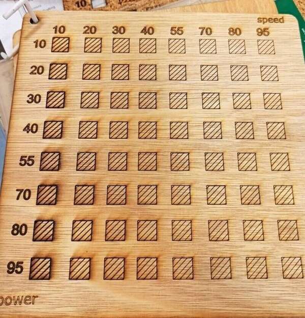
Note that the most-left column samples are cut from around 55% of power but they do not detach from the wood directly and you need to apply a bit of force to push them out.
By varying the speed and power, we can also engrave different color gradation:
The Epilog also has a “frequency” settings but even though playing with it, it did not yield visible results. It is still unknown and is left at 100%.
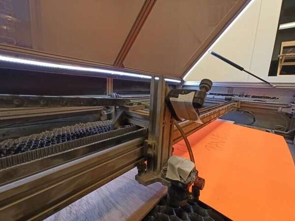
Lasersaur mirror aligning
We also tried to repair the Lasersaur in our lab that was unfortunately out of order. We, therefore, spent quite a lot of time aligning the mirrors.
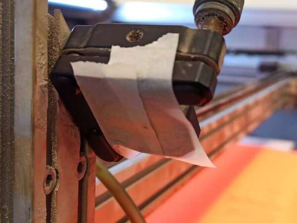
To be able to make a very short laser pulse, there was no way to do that except actually cutting an imported SVG shape. So we did a very small square shape in SVG so that a very short laser pulse will be triggered when trying to “cut” this shape.
As a student, I was more trying to understand everything and so I let my instructor guide me in the process. I don’t know if this method is recommended by the Lasersaur community neither if there are other procedures that may work ? In the end, we successfully aligned the lasers with this method but issues with the lens (weird laser shape) persisted.
4. My Vynil cutter design
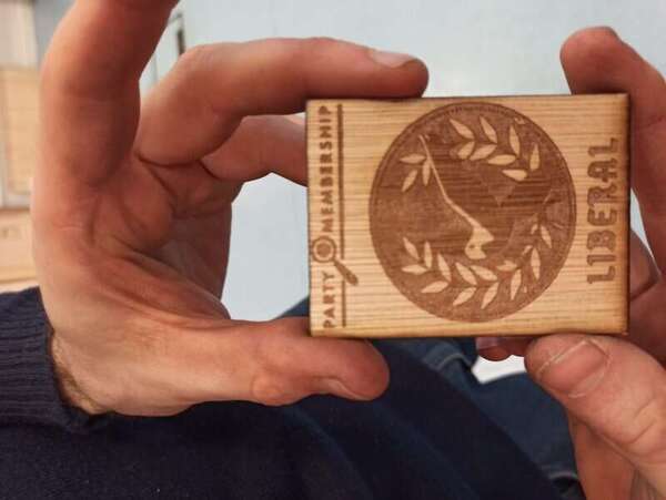
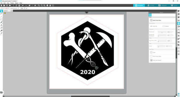
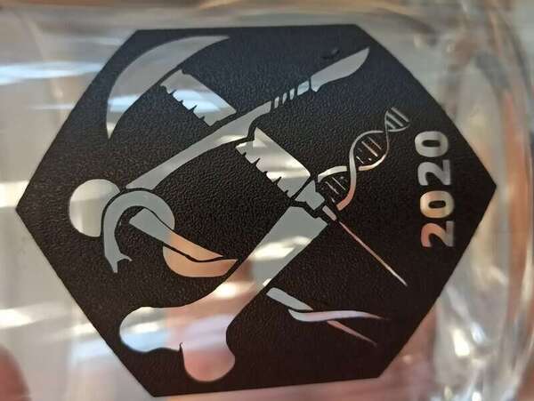
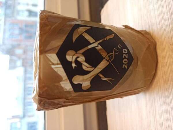
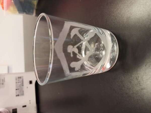
So I used my newly acquired skill to slightly adjust the logo of my last year promotion.

I first adjusted the colors in Photoshop to make the background black, then I selected the main center logo using the lasso tool before inverting the selection and removing the rest.
I was left with some unwanted pixels (due to the image rasterization) that I quickly painted in white (Locking the layer alpha channel and simply applying a white brush on inaccurate edges).
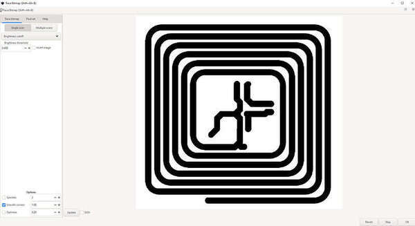
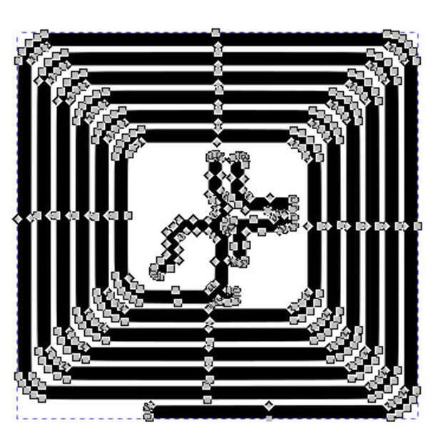
I then had to vectorize my image for the Vynil cutter software to cut it. I launched Inkscape then “Path -> Trace bitmap” and used multiple scans and tweaked some parameters to end up with a nice vectorized image!

Then I realized that to import it in Silhouette Studio, I needed a .dxf file so I tried to convert my SVG to it and ended up with a 30MB file that Silhouette never succeeded in importing…
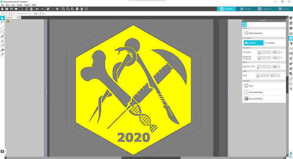
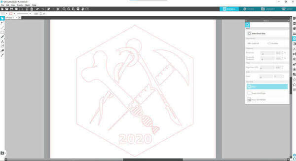
Anyway, I found out that I could simply import my PNG and it would vectorize inside the software! By choosing “Select Trace Area” and tweaking the settings I had a nice trace for the machine to cut.
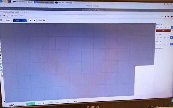
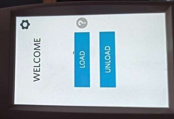
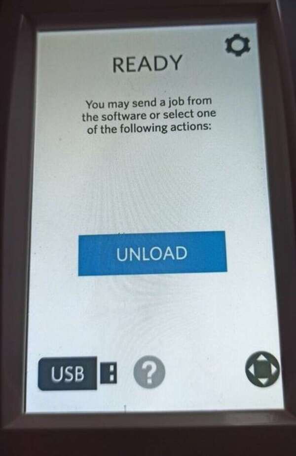
I can then start loading the paper (I don’t know which one exactly, I found some piece of it in a box, I think it’s actually vinyl) by placing it next to the blue lines and arrows on the left and adjusting the right blocker. Then press the load button on the machine.
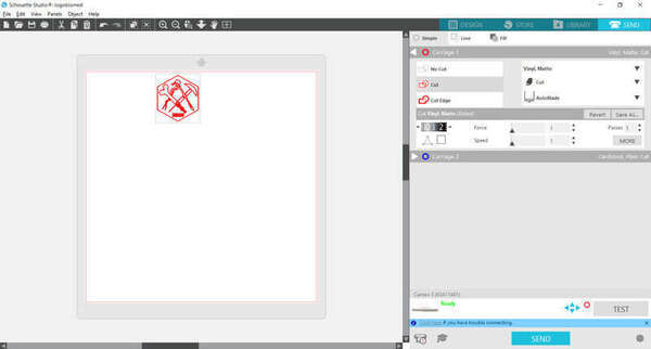
Then by clicking the Send button in the upper-right corner, you can change the settings of the blade and just cut your design. Note that I had to set the force, the speed, and the height of the blade to the minimum to get acceptable results. I tested the settings by making several lines at different settings until I realized they all shredded the paper or went through it and I resigned myself to use the lowest settings in the software (Force and speed = 1, lowest height of the blade).
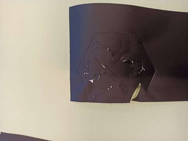
Finally everything went well and I ended up with my logo. I removed it carefully but some pieces were left on the paper:
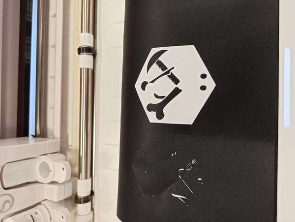
I applied it on a glass and placed the left-over on it manually:
Enters the SANDBLASTER
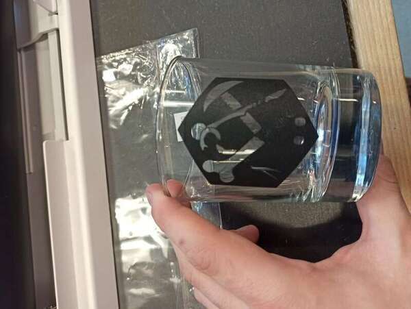
Though the glass looks nice like this, I felt like it wouldn’t last through multiple washings… So I thought about using the sandblaster. First, I covered the rest of the glass in duct-tape:
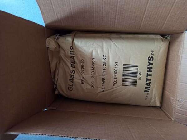
I then loaded the sandblaster with glass beads (200-300µm) and connected it to the compressor and the vacuum cleaner to their respective inputs and outputs.
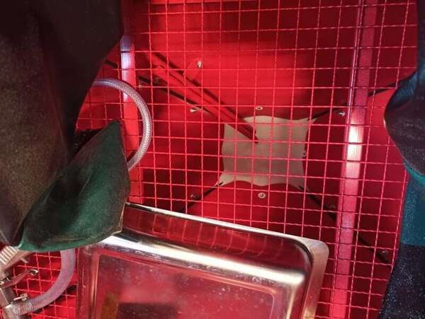
I had some trouble manipulating the “gun” and my glass in the sandblaster with the heavy gloves but more importantly, my duct tape didn’t stick well enough. I should probably have cleaned my glass with iso-propanol before to increase the “stickiness” but I’m not sure it would have made a big difference.
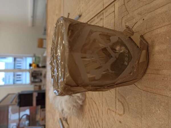
The final result is a bit disappointing and I will need to look for improvements but that’s a first step.
Trying to make a flexible circuit
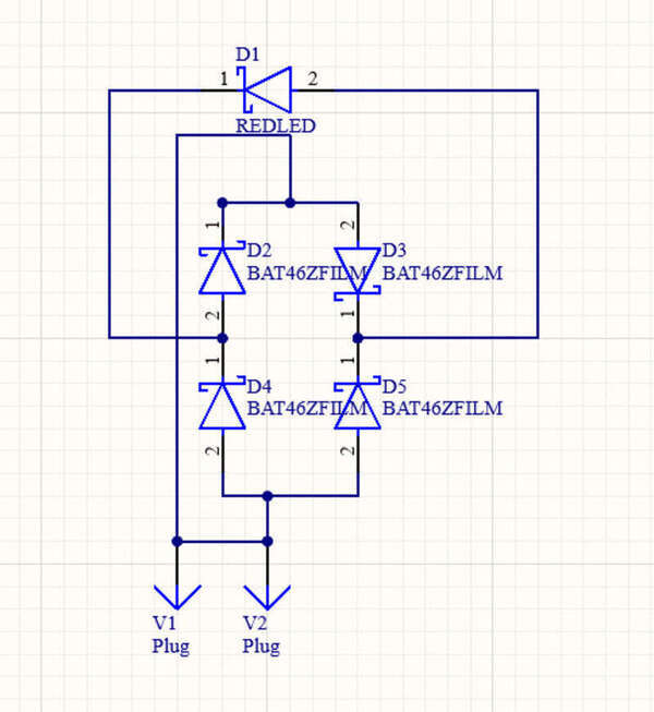
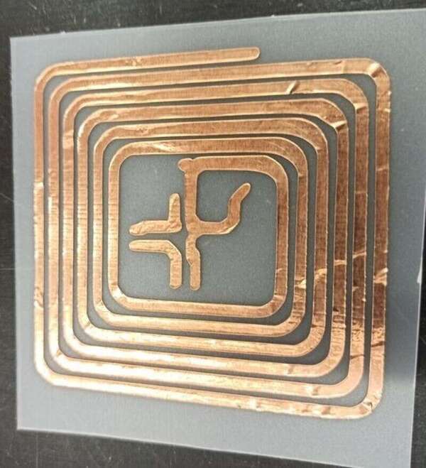
I wanted to test the capabilities of the copper sheets, sliced with the vinyl cutter to make a small, flexible PCB. I used some copper sheets that I found at the lab and made a quick simple circuit in Altium. I also wanted to avoid a power source if possible so I tried to make some loops to act as a coil so that I could use an inductive link to power my circuit. Since the current will be AC, I use 4 Schottky diodes to make a full-bridge rectifier. Finally, I chose a red LED as these require less voltage to light up. All SMD components were found at my lab and are 1206.
One of the main requirements though was to avoid sharp corners as much as possible as sharp corners will cause reflection issues when working at high frequency (as with inductive link powering).

I exported it in a PDF from Altium and then vectorized it in Inkscape just like for my logo.
The only thing that I had to look for was the actual scaling of my picture. I had to manually scale it so that the measurement on my PCB is the same as the distance on the vectorized image. The dimensions of my PCB are 78.74mmx76.2mm.
To make sure the copper sheet does not slide (it does not stick very well to the cutter holders), I taped it to a cutting mat and slid that inside the machine. Just like for the previous experience, I set all the settings to the lowest possible values.
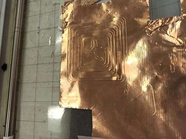
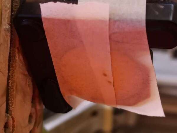
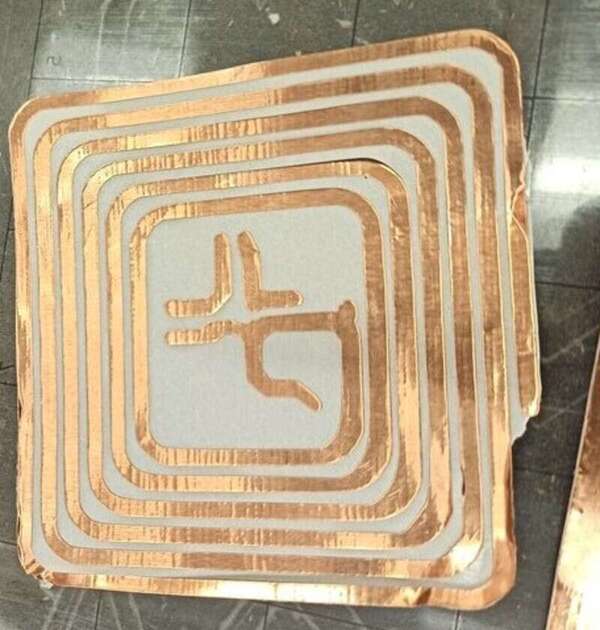
I then removed the excess of copper by using the tip of a scalpel:
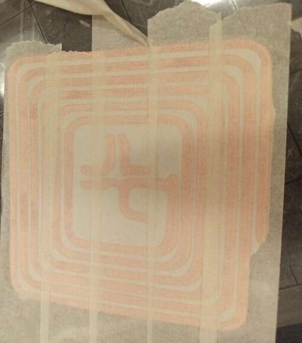
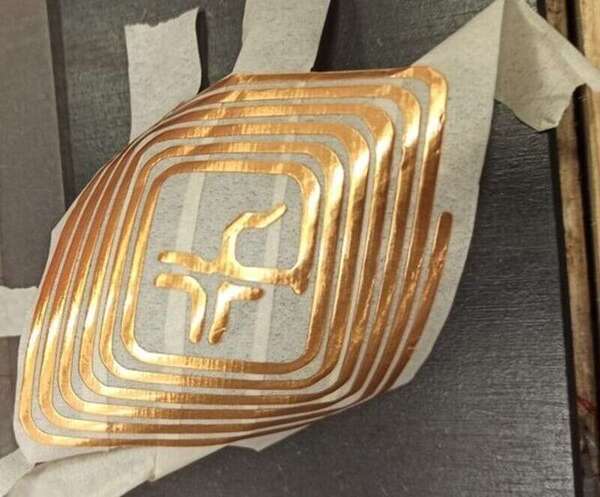
And used somes tape to make the transfer from the paper to a flexible piece of plastic I found lying around:
How it (should) work
So the main idea is that power is transmitted from a primary to a secondary (my circuit). The device should work on the principle of mutual induction between the two coils. The magnetic flux generated by the emitter coil gets linked to the secondary and a voltage is generated in the secondary (also called EMF (electromotor force)).
The EMF is directly proportional to the derivative of the current in the primary (E = -d(phi)/dt, with phi the magnetic flux captured by the secondary which depends on itself of the number of coils).
So basically, on the primary, I will need a fast-switching current. The common AC voltage is 50Hz, which is not enough. The idea is therefore to use a class E amplifier that can translate DC into an alternating current with minimal loss (an oscillator circuit).
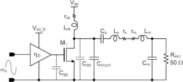
Now I won’t be making one, hopefully, I have a similar class E and coil available at my lab that is working at 300kHz.
By injecting 9V at the primary, I hope to be able to get at least a few volts after my full-wave rectifier to light up my LED (about 2V).
I will test the circuit during the next week.
Update: I did not have time to solder the components on it yet but I made a similar circuit on a PCB here and that works.
5. My laser cutter design
With the kerf, we can adjust our design so that our joints fit correctly. However, it is always best to test it ourselves. To do so, we made a kind of “comb” with several different sizes and we can therefore find the ones that fit the best.
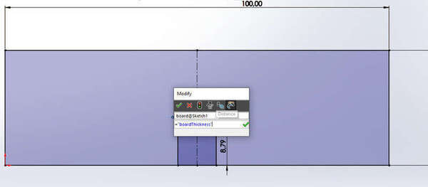
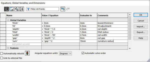
To make a parametric design in SolidWorks, I had to make a basic sketch then go to “Tools -> Equations” and there I could add my variables. In my sketch dimension, I could then refer to those variables.
To cut it, I had some trouble with SolidWorks initially: The first method I found was to make a drawing of my object and export it in a TIF file. Back in Inkscape I can trace the bitmap and scale it to the correct dimensions. In fact, this method is really not that great and I recommend using the “export as .ai” method that I describe below !
The red contour is so that in the Epilog software we can set it as a cut while black is the engraving of the numbers.
My kit
I started by defining all my parameters. AS you can see, I input the kerf value in the “fit” parameter in SolidWorks that I added or subtracted to every joint in the design.
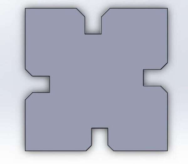
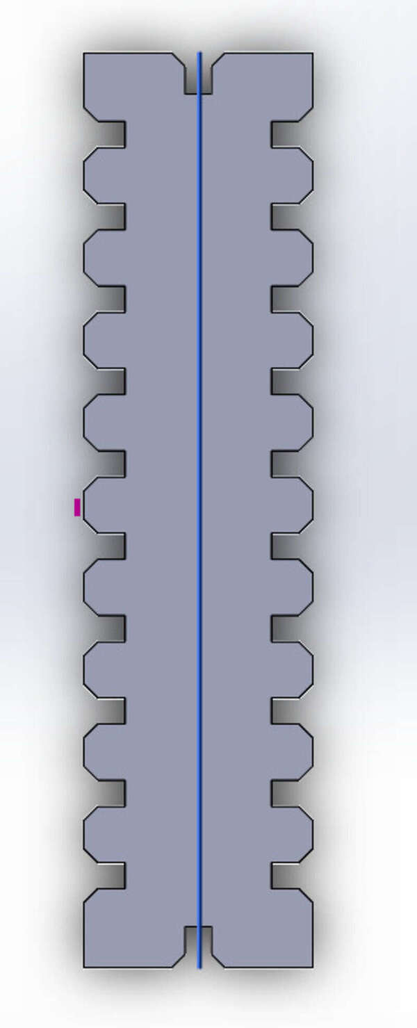
Then I made a simple square piece with press-fit joints.
Note that chamfers on the slots are almost mandatory in the design since they help fit the pieces in and compress them so that once inside, they stay there.
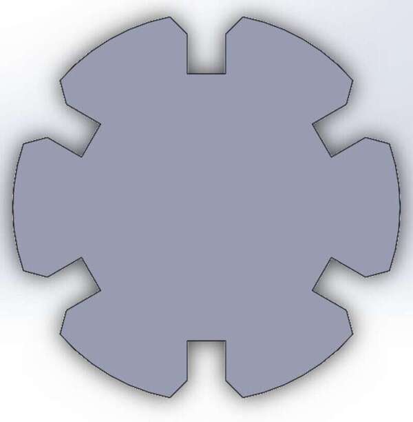
I then did the same for rectangles and circles:
Finally, I wanted to make some laser-cut parts for my little laptop table.
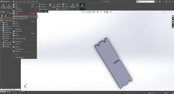
To avoid having to re-vectorize my parts in Inkscape I found a new way to export my parts from Soliworks and I highly recommend this method:
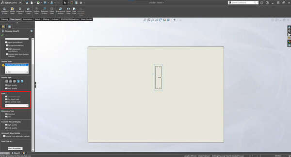
First, once my part is finished, I make a Solidworks drawing of it. I make sure to untick “Display sheet format” to remove the sheet drawings because I don’t want them.
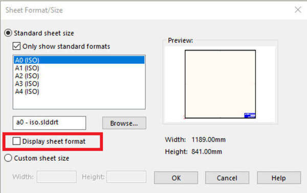
Then I place my part and make sure to put the view I want (make sure to select “custom scale: 1:1 !!!!!”). I will remove any unwanted view just after.
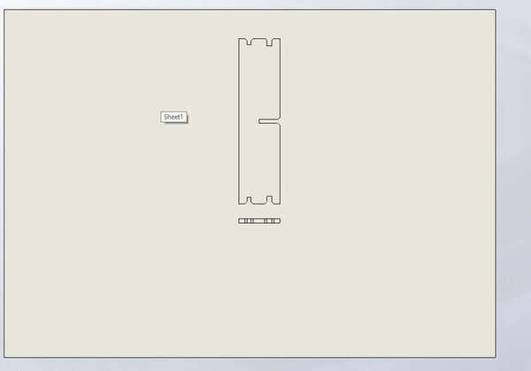
I save the document and then save it again but as a .ai (Adobe Illustrator) file.
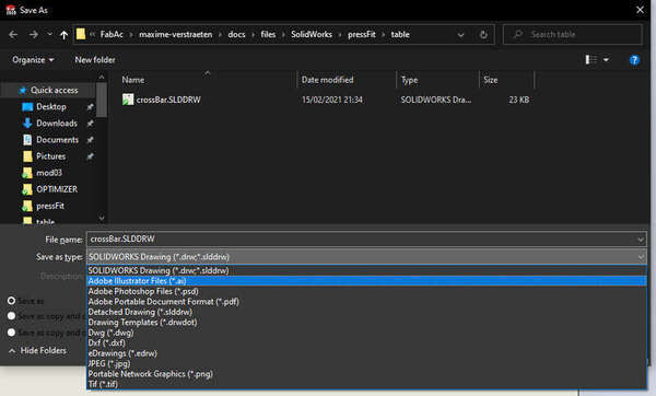
I can then open this file in Inkscape. As I have a student version I need to select the “Student” text and remove it. And we’re good to go! Add any other part you want you can send it to the laser cutter by “printing” it.
So to put my laptop on my desk I made a small little table: Here is a basic assembly of it in Solidworks:
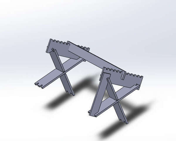
And here is the final result:
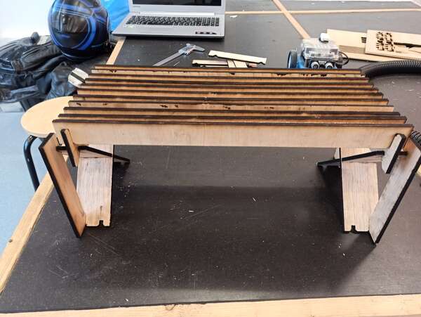
I’m not completely happy with it as it is quite wobbly. This is mostly because my wood plate bent a bit inside the laser cutter and so the focus was not right for some parts, leading to inaccurate slots. I could also improve the design by adding one or two beams to reinforce the structure.
To go further
I wanted to test the slots in cardboard to make it flex to create soft corners or curves so I’ll try to implement it later.