12. Output devices
Objectives
- Group Assignment: Measure the power consumption of an output device.
- Add an output device to a microcontroller board you've designed and program it to do something
Group assignment
This is recapped on the group page.
Consumption measured using the power supply
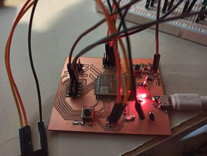
For the group assignment, we measured the current consumption of an LED on my ESP32 board right here.
Because I was powering the board with 3.3V and the current consumption increased from 0.37 to 0.44mA when lighting up the diode, I can deduce the current consumption of the LED to be 7mA which gives a total heat dissipation of 23.1mW through the LED and the current limiting resistor of 220Ohms.
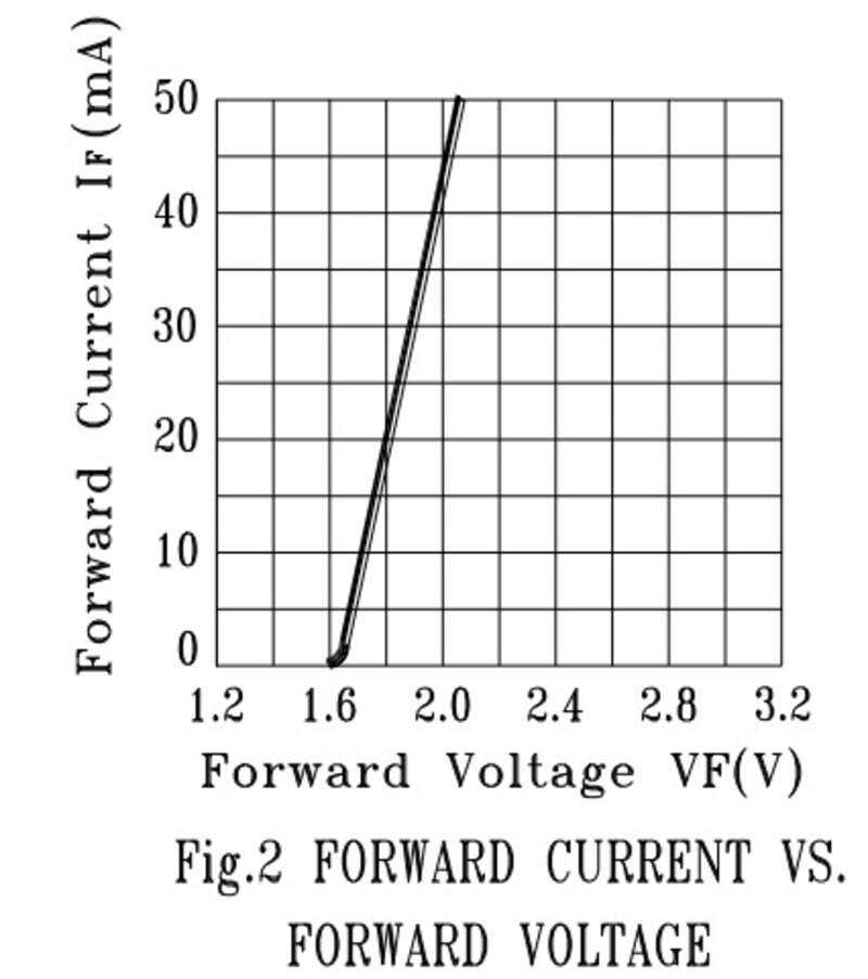
We can also compute it in another way. I have a current limiting resistor of 220Ohms and the LED has a forward voltage drop of 1.6V for 7mA. Powering from 3.3V, that leaves 1.7V through the resistor, which is indeed very close to 7mA.
Also, for another project, I powered another LED through inductive powering. I supply my class E amplifier with 9V DC and the current consumption is about 30mA (varies with the distance between the primary and the secondary of course). The power consumed is therefore about 270mW in the class E.
Using a shunt resistor
It also possible to use a very small value resistor (1 Ohm or less) to measure the current consumption. Indeed, the resistor must have a very small value to not affect the load and the correct behavior of the circuit.
It can be very useful to see the transient power consumption, for example when a µ-C is processing a lot of information,.. which is something that can happen very fast and therefore will not appear on the power supply information.
Consumption of an op-amp in buffer configuration
In fact, it is very interesting to see the difference between the theoretical circuit and the effects in practice. For example, wires have an non-negligible resistance value but also inductance value.
Inductances will oppose themselves to current variation and therefore, when we have a high current-consumer in the circuit, if it is located far away from the voltage source, charges will see a lot of inductance and will not be able to reach the consumer very quickly. Therefore, due to Ohm’s law, the voltage at the consumer pins will decrease.
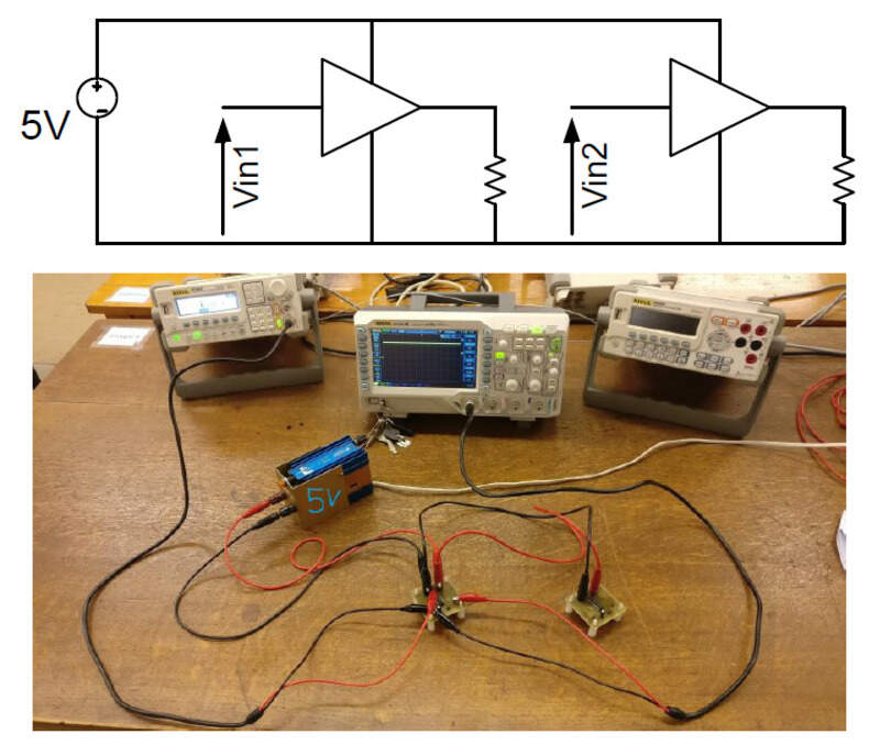
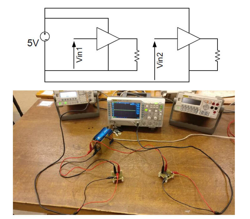
We can then compare the effect of wiring a circuit in “cascade” or in a “star” configuration.
The “cascade” configuration is the most intuitive one.
That star configuration is when every wire starts from the power supply.
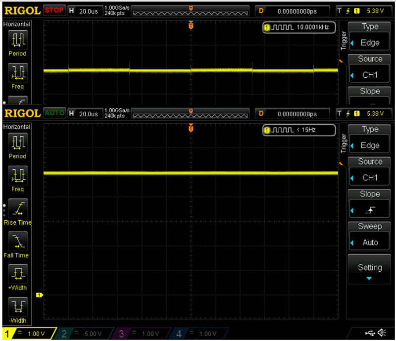
Let’s then input some high frequency (10kHz) square signal at the input of the buffer op-amp and let’s see the voltage at its pins but also at the pins on the second op-amp.
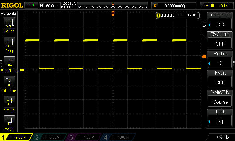
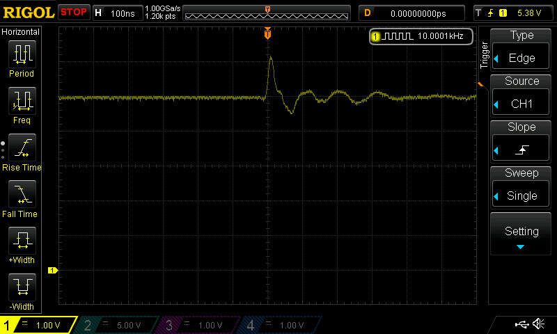
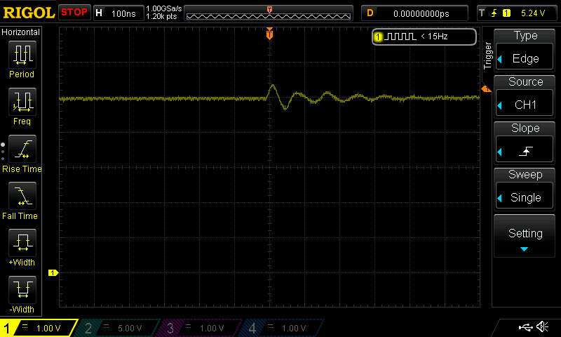
We can clearly see that the second op-amp is affected by the current consumed by the first. In a star configuration, the amount of wire in common is reduced and therefore, the second op-amp will be less impacted
This problem can be mostly solved using capacitors that will hold charges near the consumer op-amp and will be able to deliver them at a very fast rate since the inductance (the amount of wire) between the capacitor and the op-amp is very low.
Output device 1: LED 7 segments
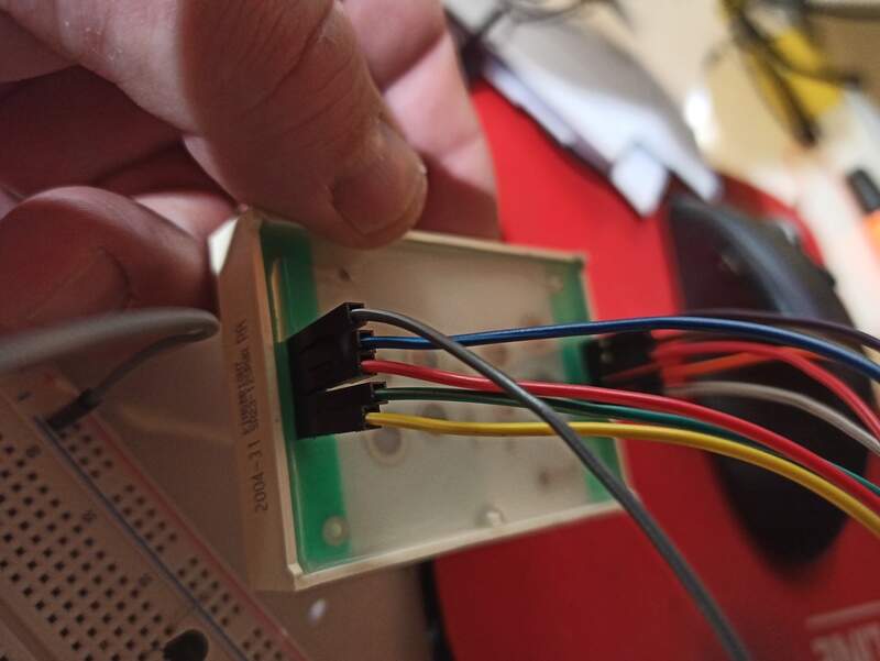
I found an LED 7 segment display KINGBRIGHT SA23-12SRWA. The datasheet is available here but is quite short.
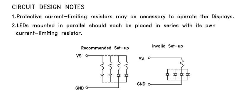
We can see it is a common anode display, meaning all the anodes of the LED are connected together. Also, there are no resistors so we’ll need to add them ourselves
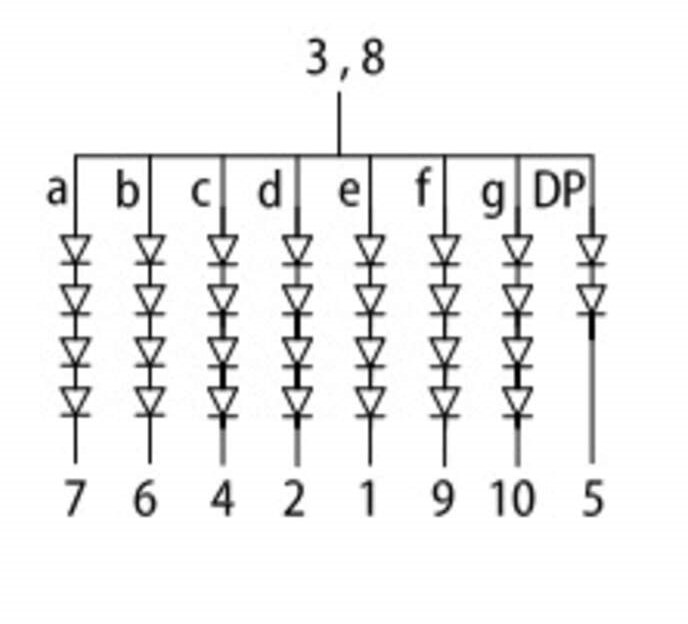
The pins are indicated for each segment and we can also see that the number of LEDs for the decimal point (DP) is less than for the other segments so we’ll have to increase its resistor value.
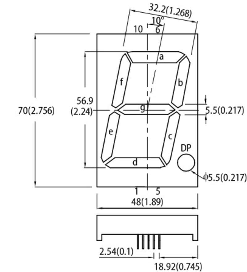
We can find the pin relation to the segments by having a look at the package diagram:
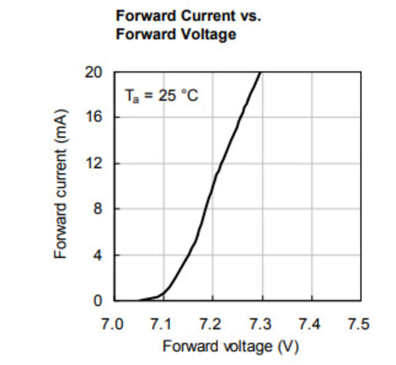
We can also see that maximum current flow is 30mA and that we’ll need at least 7V DC to light up the LED.
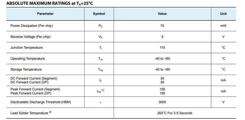
Based on this, I know I will not be able to power it directly from a microcontroller. I decided to use a 12V power supply and the ESP32 board that I already designed in the past. I also got COVID-quarantined this week so I was limited to working on a breadboard with the few components I had at hand…
Note that you cannot use a single resistor for all the LEDS as, if you do that, the diode with the lesser forward voltage (tolerance and imperfection being at play here) will receive all the current before it fries and the current goes through the next one.
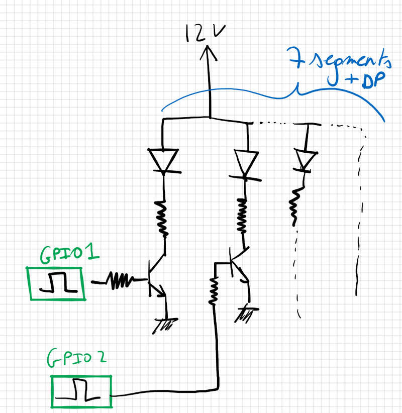
The circuit is simple: I use PNP transistors (PN2222) to activate each individual segment. The transistors are toggled using the GPIOs of the ESP32 and are in saturation from 2V (so they will be with the 3.3V output of the GPIOs). Each BJT has a base resistor of 1kOhms and the LEDs are limited in current by a 100ohms resistor each.
Making the circuit
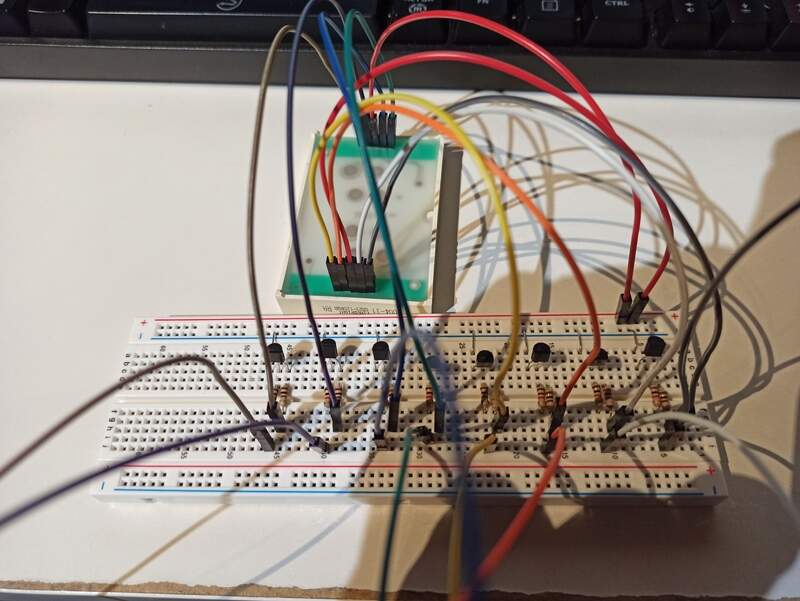
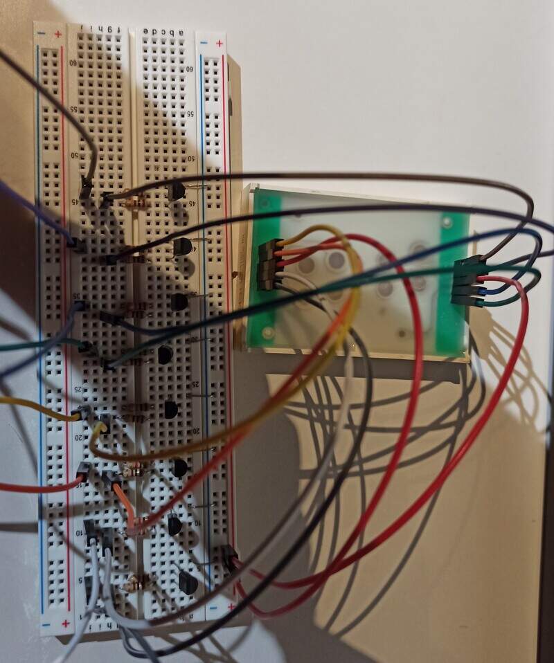
As said, I didn’t have access to the CNC engraver so I did my work on a breadboard but I took special care to make sure it is readable and well-organized.
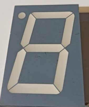
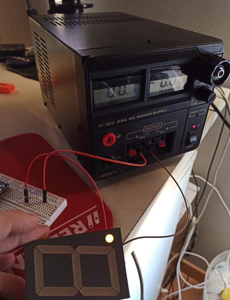
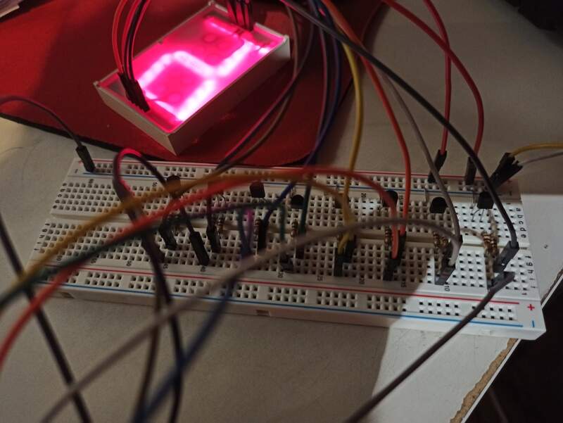
I first tested the displays by powering a single segment (the DP here) by supplying it with low voltage:
Then when I was sure it worked, I made the breadboard design:
Then I tested to toggle the transistor with a commercial devkit for ESP32.
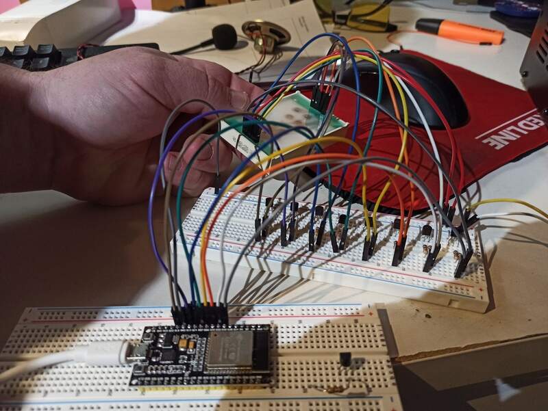
Then when I knew it worked well, I connected it all to my own ESP32 board.
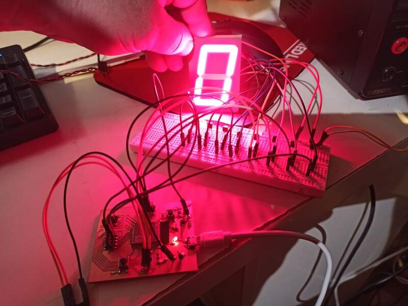
Counting to 15!
Once I could get a simple zero to show up, I made a quick code to go from 0 to 15 (or F in hex) and blink the decimal point twice as fast. Pretty simple all in all. I first made my truth table for all the numbers and I then apply it in a function by reading the bits (by applying a mask) and selecting the correct segment to light based on the bit value:
1 2 3 4 5 6 7 8 9 10 11 12 13 14 15 16 17 18 19 20 21 22 23 24 25 26 27 28 29 30 31 32 33 34 35 36 37 38 39 40 41 42 43 44 45 46 47 48 49 50 51 52 | |
A zoomed out view 
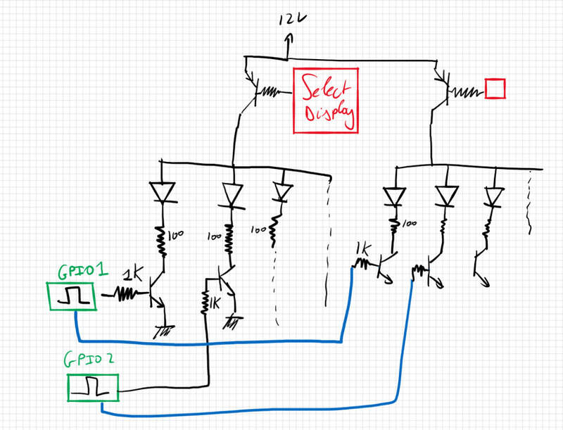
Possible improvement and extension
With NPN transistors, it would also be possible to multiplex multiple displays. We then link each display segment together (a’s with a’s, b’s with b’s, …) and we select the display we want to light up by toggling the corresponding NPN transistor to allow current from the 12V supply to flow. The eye “low-pass filter” will simply let you see all displays light up together even though they toggle real fast. You therefore need 8(7 segments + DP-) +1 per display(selectDisplayPin) pins in total instead of 8 per display.
This requires NPN transistors, as it is impossible to do with PNP (VB should be close to 12V which I cannot supply) so I couldn’t do it this week but it isn’t difficult per se.
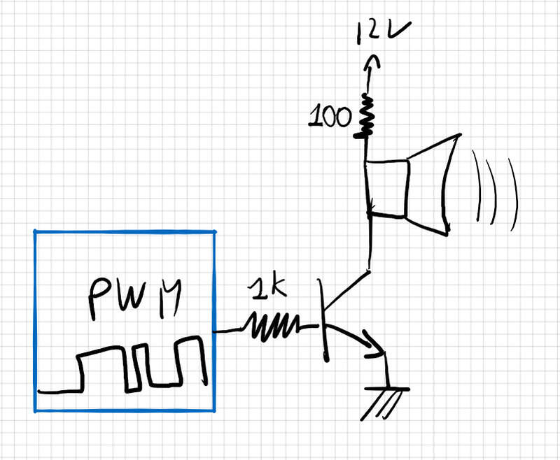
Output device 2: speaker
Finally, I had a speaker lying around so I gave it a try as well. To make it work, nothing is complicated electrically as it is a simple coil that you make vibrate through a PWM at a set frequency for each note.
Obviously, I chose to power it from 12V as well (but it could work with 5V as well, without needing a resistor then) and the inner resistance of the speaker being 8ohms, I protected it with a 100Ohms resistor and the base resistor is again, like for the first project, 1k as well.
I then found a nice code to modulate the PWM using the “ledc” functions of the ESP to obtain notes and melody! (credits)
Here is my version of the code:
1 2 3 4 5 6 7 8 9 10 11 12 13 14 15 16 17 18 19 20 21 22 23 24 25 26 27 28 29 30 31 32 33 34 35 36 | |
And the nice result:
You can see I used my commercial devkit to test it out and then I later broke my USB-B connector on my own board without a means to solder it back so it was good news I had the commercial board with me!