Inputs, outputs, electronics, and encapsulation
There are multiple inputs and outputs in this project.
Chamber pressure
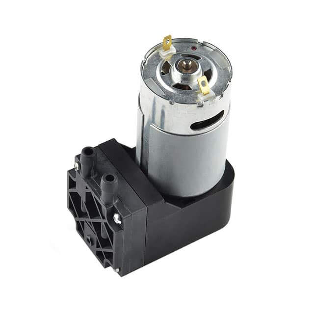
To handle the chamber pressure, I chose a vacuum pump from Digi-key for its low price and availability. It is a very simple DC pump (ROB-10398) that I will connect to an L293D motor driver and control via the ESP32 (see below).
Phantom filling
To fill the phantom with air or water, I will use a cheap no-name 12V DC peristaltic pump available from Amazon. Because they are cheap, I am going to use two of them to reach the correct flow rate (cystometric rate of 10-100mL/min and physiological filling rate of 1.4mL/min).
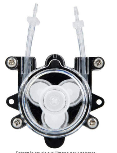
Also, because they are cheap once again, I use “inertia” tanks to smooth the response curve.
They will be controlled like the chamber pump with the L293D.
Data visualization
TFT Screen
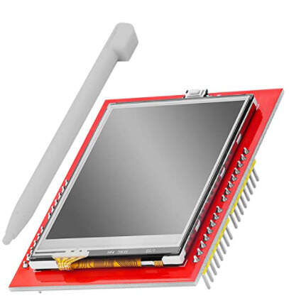
To output some data like the current flow rate or pressure, I initially wanted to use an LCD TFT screen. One of the most common LCD driver is the ILI9341. Multiple brands sell boards with this LCD as well as a touchscreen interface.
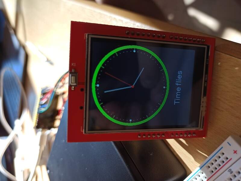
I was hoping to be able to communicate with it through the SPI interface (the ILI9341 is capable of that) but I chose the wrong brand (AZdelivery) for the board that redirected the SPI to an SD card reader. It is then only possible to send data to it using the 8-bit parallel bus, which requires a total of 12 pins to make it work, which is a lot on a small ESP32, already dealing with other inputs and outputs.
It works, but I won’t be able to use it for this project. One solution would be to use a shift register to go from serial (one pin) to 8-bit parallel to the LCD screen but it would require a lot of additional work.
Alphanumeric LCD
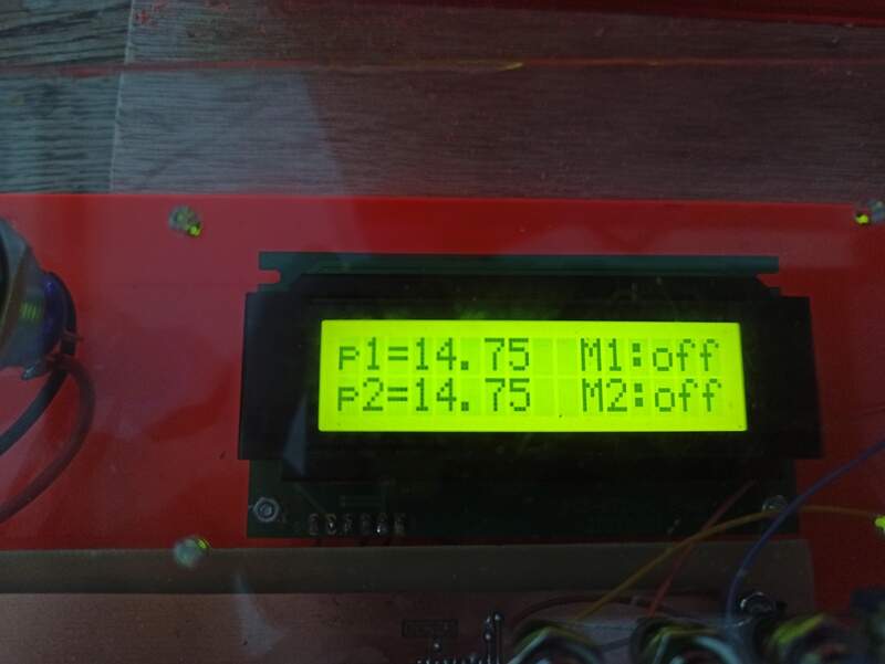
I chose then to use an alphanumeric LCD screen (16x2 characters). It is a Batron BTHQ21605AV-YETF-LED04-12C-5V. It communicates through I2C and the pinout is available in the datasheet.
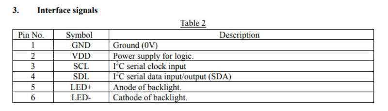
Its I2C address is 0x3B. The LCD driver is a PCF2119. Unfortunately, there are no libraries to make it work so I had to look at the various registers to send the correct commands to be able to output data on the screen.
1 2 3 4 5 6 7 8 9 10 11 12 13 14 15 16 17 18 19 20 21 22 23 24 25 26 27 28 29 30 31 32 33 34 35 36 37 38 39 40 41 42 43 44 | |
Control inputs
To control some parameters like the pomp flow rate, I use a potentiometer and some push buttons that are connected to the ESP32.
Initially, I also wanted to use the LCD touchscreen to be able to control some variables.
Inputs: pressure measurements
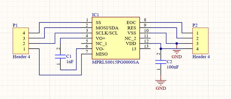
To control the pressure inside the chamber, it is nice to have a measurement of this. To do so, I chose a pressure sensor that can measure up to 2 bars: the MPRLS0030PG0000SA. I wanted it to be reachable using I2C but this version was not available on the vendors I checked, so I took the SPI version.

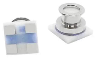
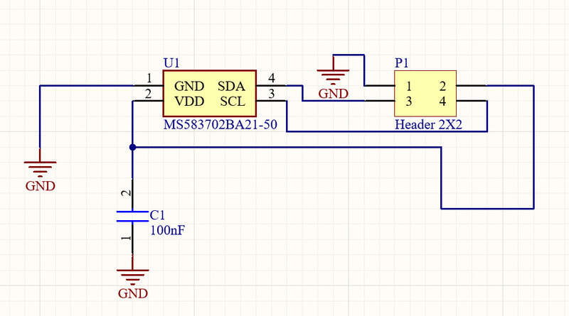
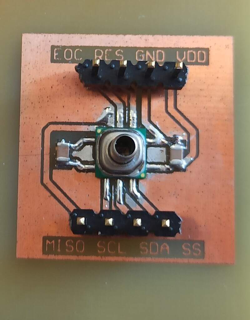
For the pressure of the phantom, the pressure increase is much less, around 196mbar maximum. It must also be waterproof. I will also need an absolute pressure sensor because it will sit inside the pressure chamber so the “outside” reference will be false (it also makes sense for possible implantation of the sensor in a real use-case).
I chose the MS5837.
It is communicating through I2C but the address is fixed. I am going to need two of these sensors so I plan to use an I2C multiplexer like the PCA9846. The other possibilities would include: - selectively unpower the one we don’t want to talk to: also adds additional hardware and is far from perfect. - having manual jumpers to change the configuration: not suitable for simultaneous acquisition - having a reprogrammable address would be nice but this is not the case
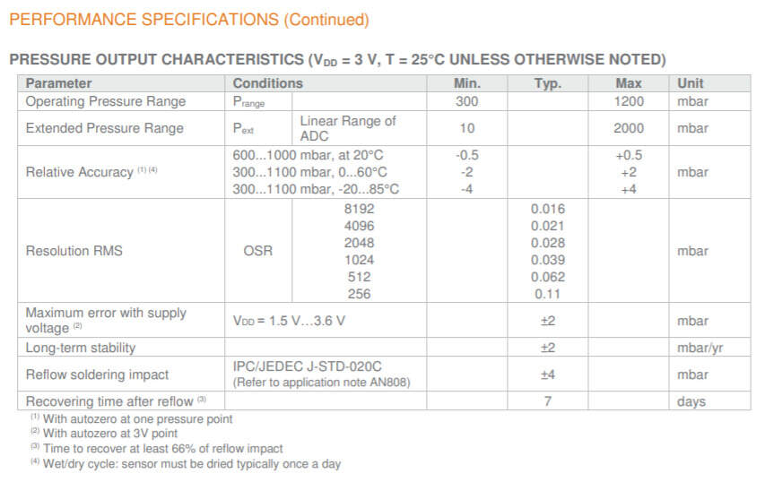
It does not seem perfectly waterproof but nothing in stock is waterproof. The pressure is going to be small and it should be able to resist that according to the datasheet.
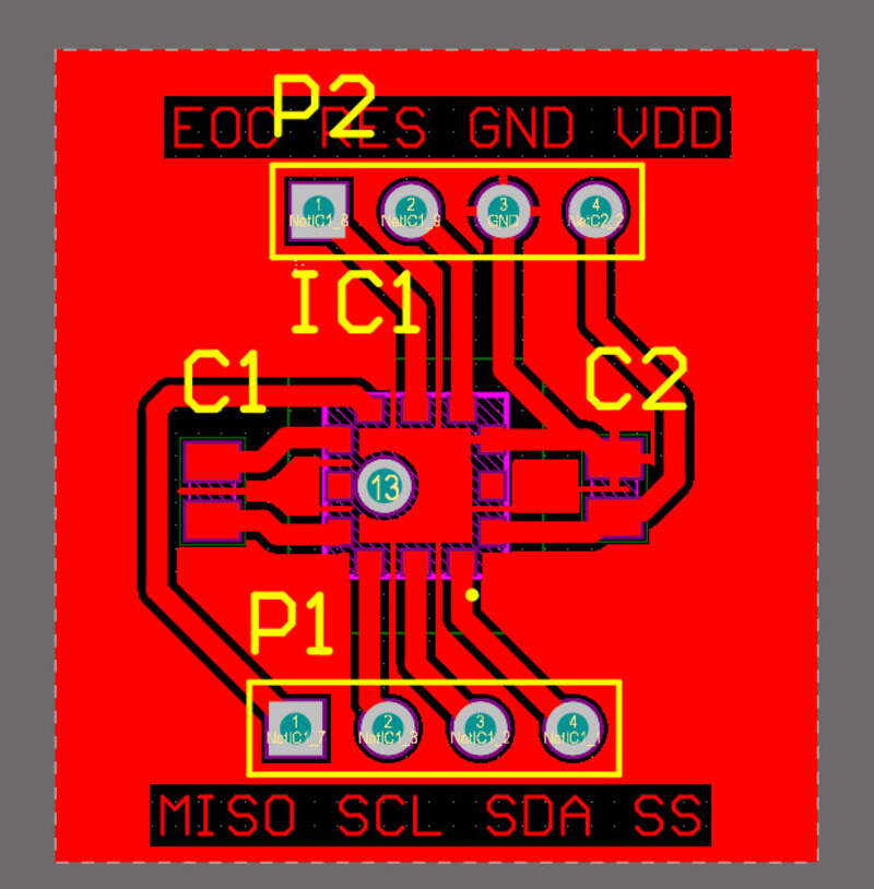
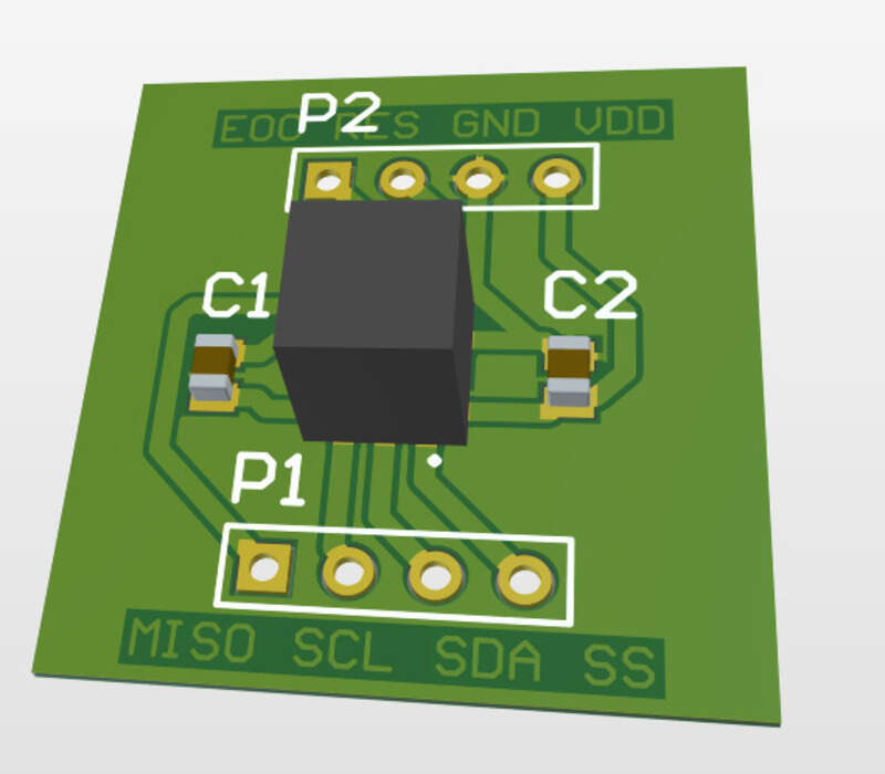
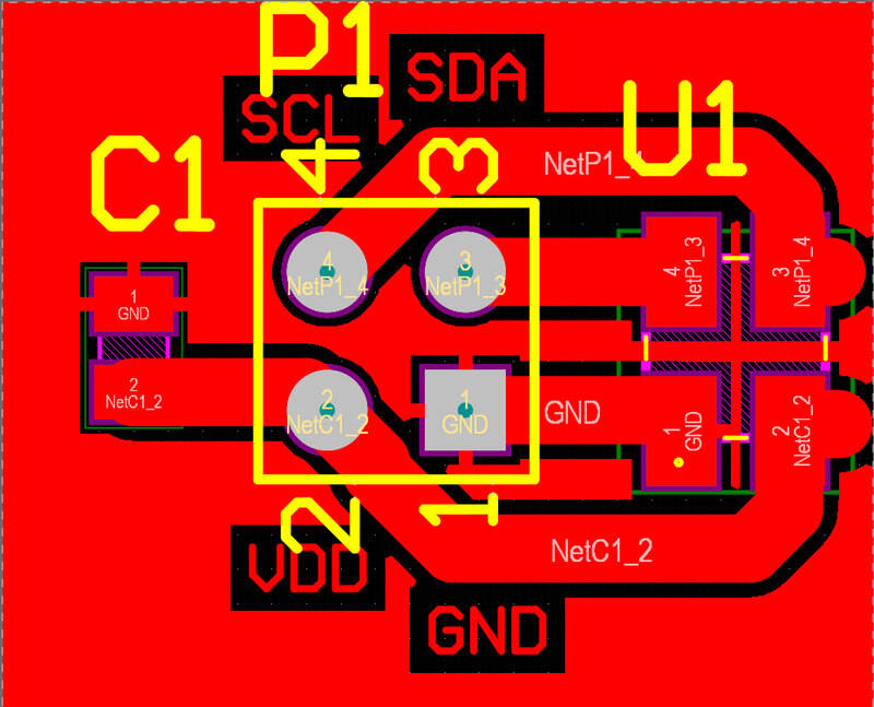
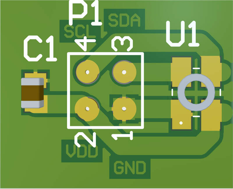
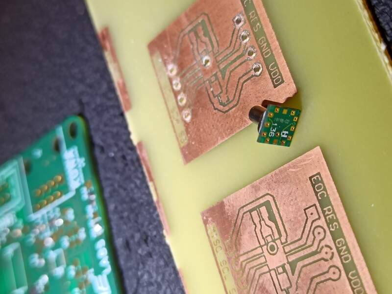
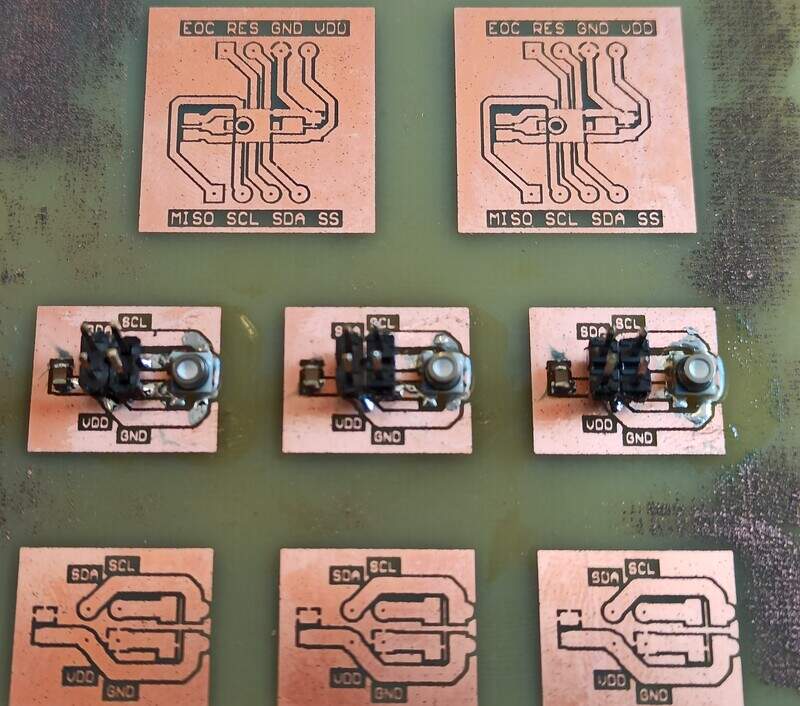
I made two “breakout” boards to use them with pins and decoupling capacitors. For the MPRL:
For the MS5837:
To be more complete, I would need to add pull-up resistors on the I2C lines. I added them with a bit of hand-soldering afterward.
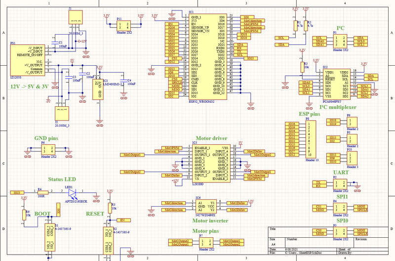
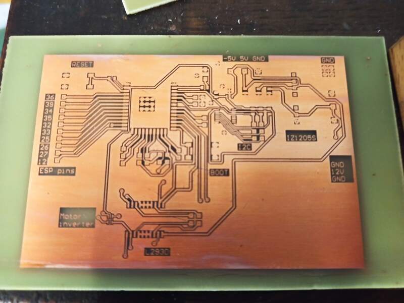
The microcontroller: ESP32
I chose to use an ESP32 for multiple reasons. The first being the fact that it is a very high-end microcontroller, with a lot of memory and a lot of IOs. It is also capable of Bluetooth and Wifi communication if I ever need them. I can program it using the UART pins.
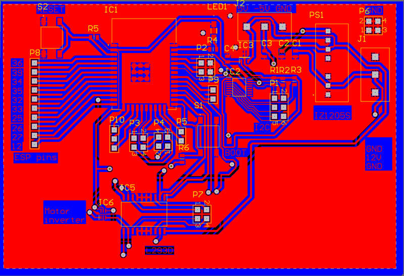
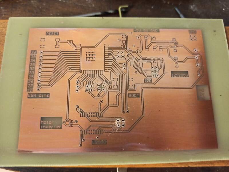
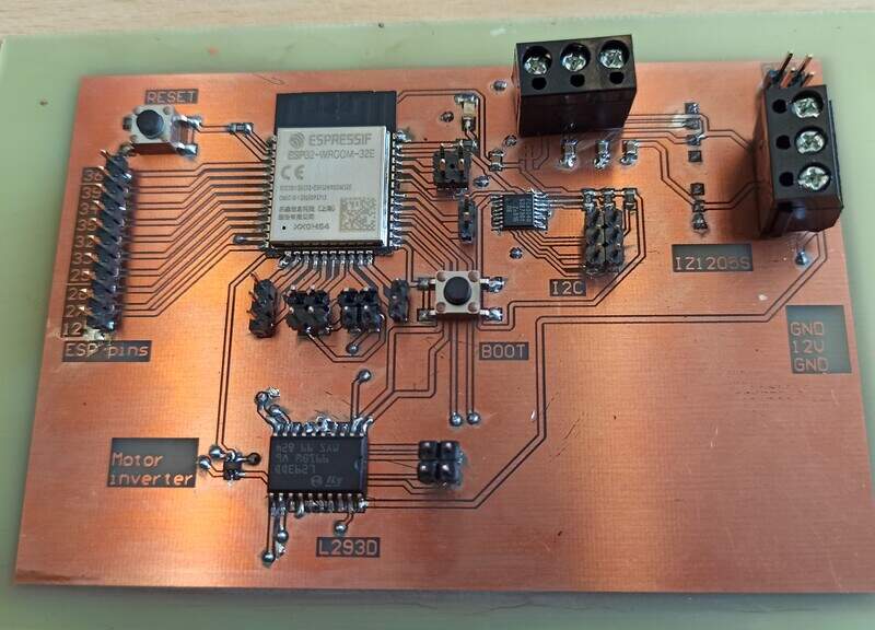
I made a board that features the ESP32, but also the 12V voltage regulator to +-5V and to 3.3V. I added an LED on the GPIO 23. There are two buttons to enter the programming mode of the ESP. There is an I2C multiplexer, as the two pressure sensors share the same address so I have to place them on two different I2C buses. Finally, there is an L293D motor driver and a CMOS logic inverter (NC7WZ04) to help control the motor by creating the opposite signals which reduce the number of outputs of the ESP required. Finally, a lot of headers are present to connect to various I2C, SPI, and UART devices and to connect buttons, toggle switches, …
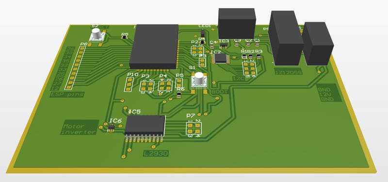
You can see the board is working well and I can program the ESP to make the LED blink on GPIO23.
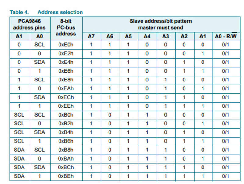
The I2C multiplexer has the address fixed by the conections made to the A0 and A1 pins, in my case, the address is 0xE2h (8-bit), or 0x47h for the 7-bit address.
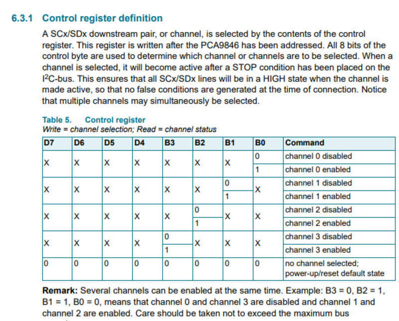
To choose the channels on which to communicate, I send a byte containing 4 bits that indicate the active channels (out of the 4 available) to the PCA on the main I2C bus.
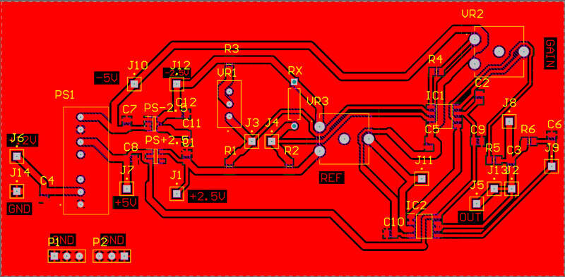
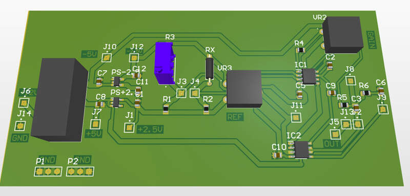
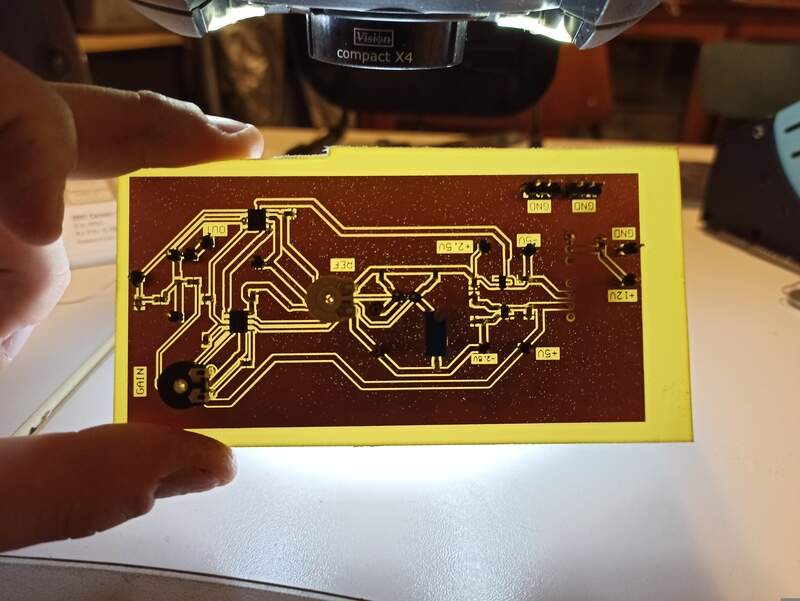
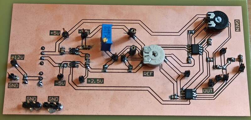
Strain gauge acquisition chain
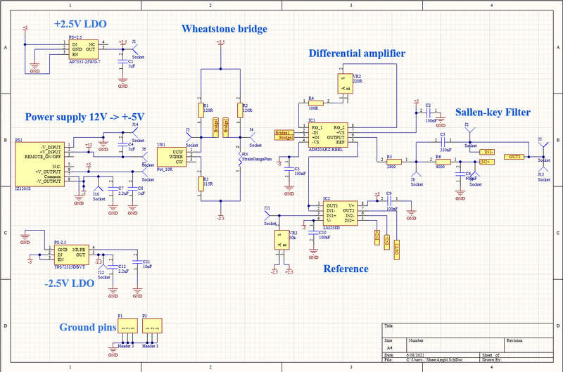
To measure the strain gauge deformation, I use a Wheatstone bridge made of 4 resistors, a potentiometer for bridge balancing, and an instrumentation amplifier (AD620). I supply my bridge with +2.5V and -2.5V coming from an initial 12V -> +-5V (IZ1205S) and then two LDOs (TPS72325 and AP7331-25). The reference of the amplifier comes from a potentiometer going through an op-amp buffer. The gain of the amplifier is set with a resistor and an additional potentiometer. Finally, I use a Sallen-key low-pass filter of order 2 to remove most of the signal noise.
I initially thought about using a digital potentiometer but the main issue with these is the non-zero wiper resistance and the limitation to being stuck between GND to VDD, which does not allow me a symmetrical choice of voltage as I did for the reference (-2.5V->+2.5V).
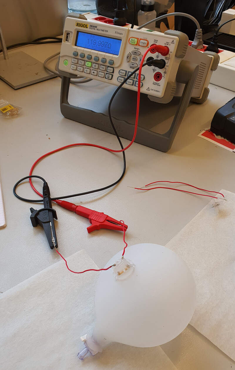
You can see on this video how the voltage at the output of the acquisition chain changes with how I deform the beam held in the vice with a strain gauge glued on it.
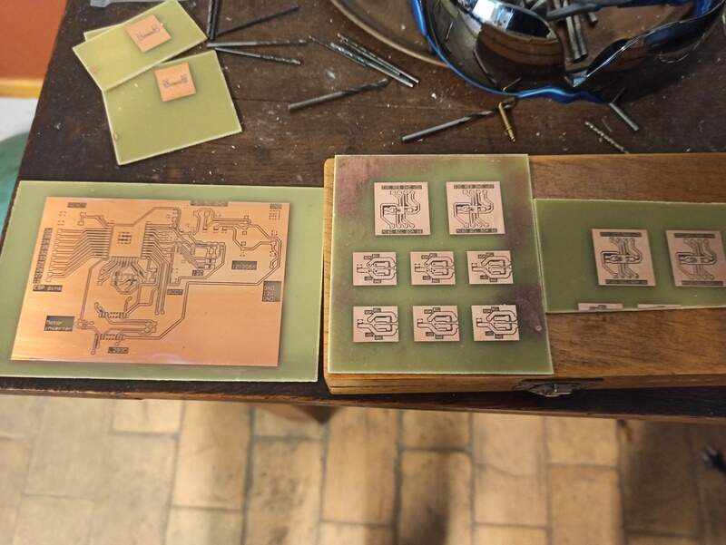
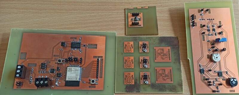
The PCBs
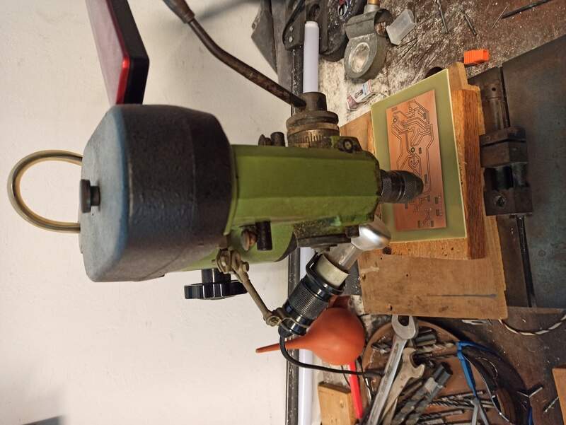
I made all my boards using chemical etching because I didn’t have any good mill bits left and no more FR1 copper plates. Also, for the ESP board, I could simplify my design by making it double-sided.
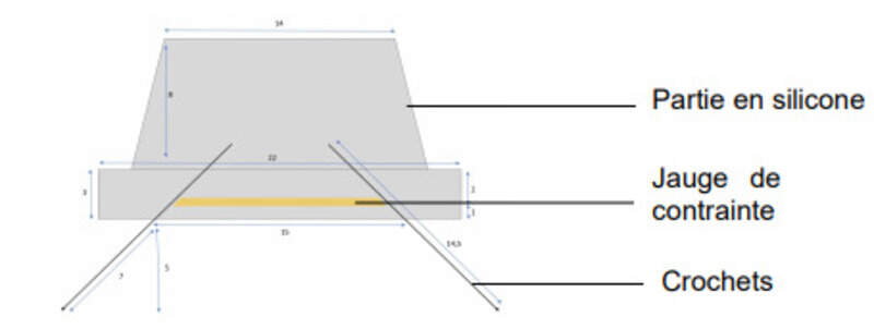
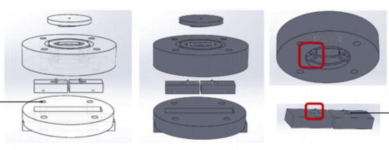
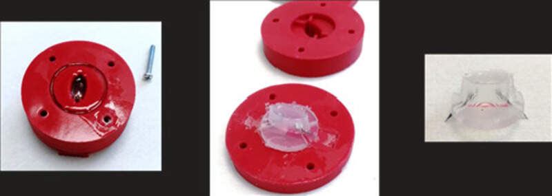
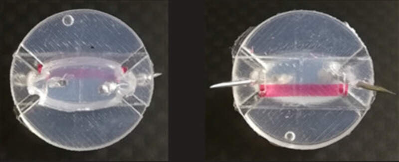
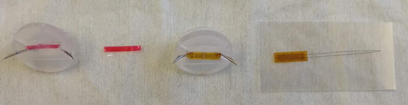
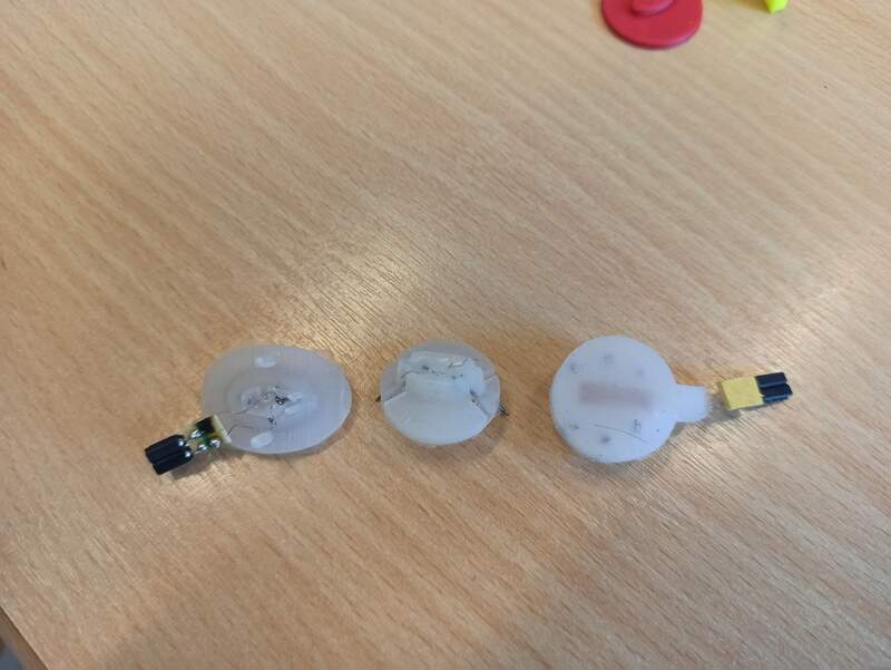
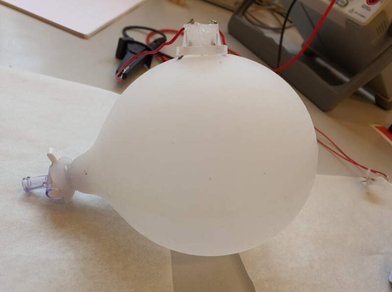
Encapsulation
To be able to follow the bladder deformation, I encapsulated it into some Ecoflex0050 silicone. I made molds, poured the silicone, and tried out different designs with pieces of plastic before encapsulating a real gauge.
Possible improvements
I could add a solenoid valve to handle fast compression in the chamber by filling a pressure tank and releasing it in a short amount of time through the valve. This would allow the simulation of detrusor contractions.
It would also be nice to be able to empty the phantom with a valve after the experiment.
A humidity sensor would be interesting to add, especially in the strain gauge encapsulation.