Machines that make
Dynamic area projection mapping
For a while I’ve got an idea in my head, what if taking a projector and putting it on the platform which could yaw and pitch. Such setup would allow projecting something at almost any wall or object in the room. Then, taking this room and represent it inside some real-time 3D software, we should be able to position a virtual camera anywhere inside this virtual space. Now, if I position camera origin in virtual space at the same exact spot as projector’s lens center in real space also adjusting orientation, then changing camera’s focal length to correspond projector’s lens parameters, I should be able to project the virtual space’s surfaces onto the real space’s without distortion. Synchronising projector’s position with camera’s should allow projecting any surface in virtual space to any corresponding surface in a real space. Representing the real space in virtual environment could be done manually or using 3d scanning techniques.
Required features
Hardware
◤ Yaw 360° and pitch at least 90°
◤ Adjustable level and alignment
◤ Allow HDMI and power cables to twist freely
Software
◤ Output 3D camera view to projector in full-screen mode
◤ Serial communication with motor controller
Designing sketch in FreeCad
First, I made some sketches in FreeCad to understand what will be required for this project. From model below I can say that I’d need to design:
◤ Some stand to mount the machine on top and leave space for cables below
◤ Turntable to achieve yaw movement
◤ Platform to achieve pitch movement
◤ Inputs and mounts for 2 stepper motors
Switching to Fusion360
From this point I decided to use Fusion360 because it allowed seamlessly collaborating with my mentor. We have agreed he is making the pitch part which is a platform on U-shaped frame and I making the turntable and the stand.
▼ The turntable (bearing?) section-cut
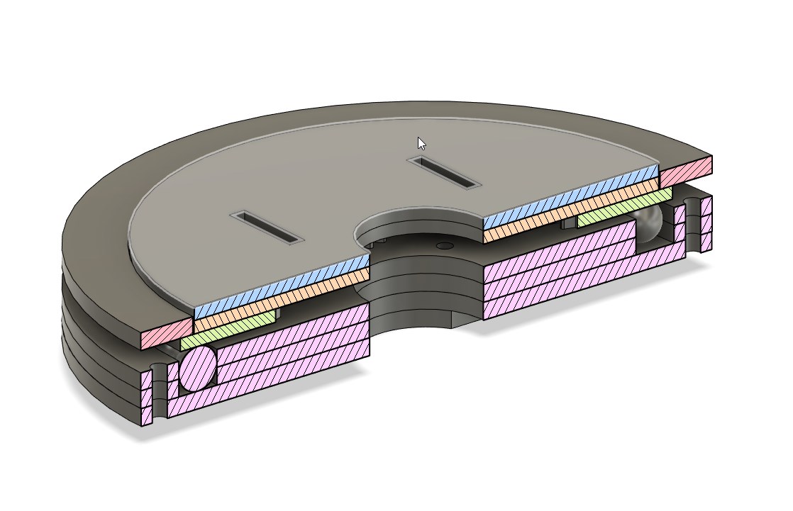
▼ Bearing in action
Laser-cutting the prototype
The whole construction is easily produced with laser-cutter, and utilizing mostly plywood and some acrylic.
▼ Cutting-out stationary pieces
▼ Cutting movable parts
Assembling
As the parts are ready let’s proceed with assembly. Starting from stationary disk that holds with boltd and continuing with a moveable disk that is glued acrylic.
▼ Stationary disk
▼ Rotative acrylic gear-disk

This part will sit on top of metal spheres and contact with plywood cap-ring. Making both movable and stationary pieces from plywood would not allow contact surfaces to slide easily producing too much friction.
▼ The gear

Here the surface under the gear is covered with glue just because I accidentally did it. It isn’t a contact surface, so this hopefully would not affect overall performance.
▼ The spheres
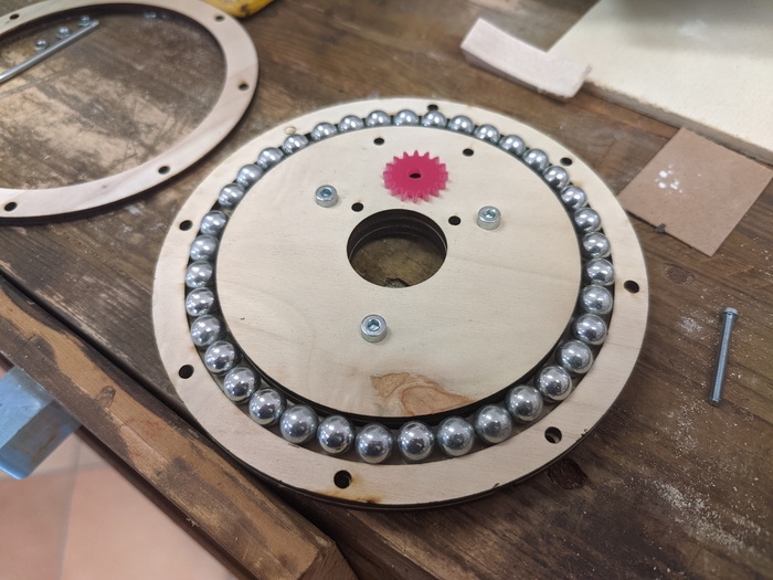
▼ Yaw bearing assembled

Just checking if part is functional. Final assembly would require mounting top part first because I want press-fit the pitch-frame and that would require hammering it into acrylic disk.
▼ Gluing the pitch-frame
The top part was outsourced to my mentor Antonio and here he is assembling it.
▼ The pitch-frame is press fitted into the disk

▼ The podium side-bearing

▼ The issue
Here is small example of some collaboration quirks. The top part was made by my mentor and the bottom by me. The result is unfitting, but hopefully could be resolved.
▼ The yaw-pitch part is ready being assembled

Here I’m using springs to fill the remaining space between the stationary disk and the top cap.
▼ Resulting assembly

▼ The wobbly stand
The stand came out a little wobbly in one axis but pretty sturdy in any other. During operation this could be a problem so further implementations would require additional structural pieces to achieve rigidity or increasing the sheet thickness.
Communicating with Blender by serial
Thinking about real-time 3D software that allows serial communication and also outputting the camera view in full-screen mode I decided to try using Blender. Finding this tutorial promised me easy solution for prototype and overall proof of concept. Using Arduino with Grove starter-kit I was trying to control the camera rotation in blender using potentiometer.
▼ Arduino with Grove shield and potentiometer

▼ Arduino sketch
String CommandFromPC;
const int potentiometer = A0;
void setup() {

  CommandFromPC = "";
  Serial.begin(115200);
  pinMode(potentiometer, INPUT);

}

void loop() {

 if (Serial.available() > 0)
 {
    int value = analogRead(potentiometer);

   CommandFromPC = Serial.readStringUntil('\n');
    if (CommandFromPC == "dist") {

     Serial.println(value);

     }
 }
}
Here is just a simple serial communication. On each communication cycle program reads the potentiometer pin
A0and then if the stringdistis received printing the value as a new line.
▼ Flashing and checking the code
The code is working and now to blender.
Communicating Arduino with Blender from Sublime Text
3DS Max is the editor I have the most experience working in, but for this project it’s missing one function that is maximizing view-port to achieve 1 : 1 camera-view projection. Without full-screen it would be not possible to project virtual surfaces correctly so I chose Blender which allows maximizing the view-port into full-screen leaving no borders or bars.
▼ Entering the full-screen mode
▼ Using Ctrl Alt Space to maximize the view-port
▼ Blender Python script
import time
import bpy
import serial


ser = serial.Serial('COM7','115200')
time.sleep(3)
ser.write(b'dist\n')
angle = float(ser.readline())

camera = bpy.context.selected_objects[0]

for x in range(10000):


    ser.write(b'dist\n')
    current = float (ser.readline())
    rad = current * 0.0090016981518625
    print(rad)
    camera.rotation_euler.z = rad

    bpy.ops.wm.redraw_timer(type='DRAW_WIN_SWAP', iterations=1)

ser.close()
This script is sending the
diststring to previously opened serial port and then reading serial output and mapping it to radians. In the final step its assigning radians value to camerarotationproperty. Also, to redraw the view-port I’m using hack from Blender-Wiki which is that line:bpy.ops.wm.redraw_timer(type='DRAW_WIN_SWAP', iterations=1).
▼
Controlling the motors using GRBL and CNC shield
To control the motors I’m using GRBL
▼
▼
▼
▼