Computer-Controlled Machining

With the idea from cutting week in my head I’ve started this assignment. Will the construction-kit work for larger scale? Lets figure out!
Design
Scale adjustment in FreeCad
The first ting to do is to scale the model. Thinking that I just need to edit parameters in the spreadsheet to desired values, but it was not the case.
Issue
Going from 150 mm to 600 in spread dimension eventually was breaking the sketch. The problem was that dimensions that was not attached to spreadsheet parameter would behave strange if the sketch updated from spreadsheet. Liking this dimension to spreadsheet made the model behave better on change but even with that to big increment in change could break the sketch.
▼
👁 The scaled assembly wth 5m thickness
Starting a new assembly I would require more parts, so I spawned different configurations to have some range I can play with.
The process requires some clicks and menus on each part placement but keeps it pretty simple and intuitive to assemble. I would describe it as inserting some part from a range and then tweaking position to achieve some geometry and then repeat as many times as possible with ready parts until additional piece is required, then spawning a new part with desired properties. Iterating through this, I required to create some additional cutout and hole configurations of the part as well as adding different lengths parts.
▼
▼
▼
▼
Inputing new pieces requires some basic math in main spreadsheet to adjust the lengths. It’s also possible to use sketched geometry assigning reference dimensions to pieces you want to measure based on some shape configuration.
▼
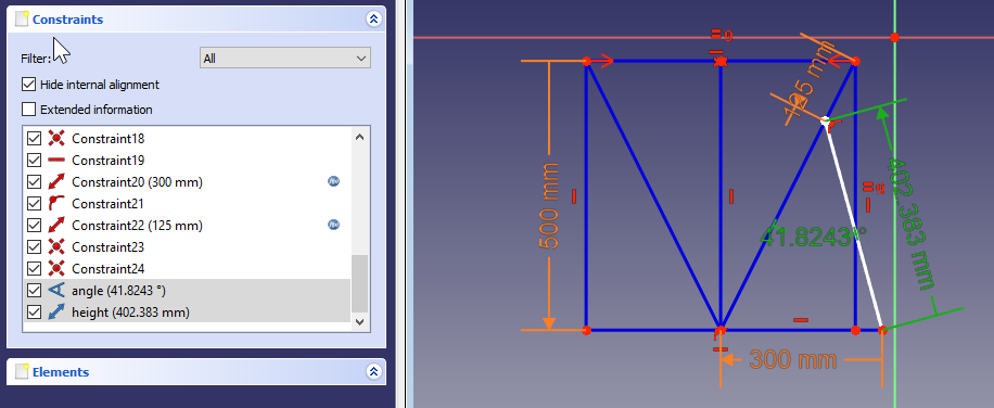
Here, I’ve created additional file named it ref and sketched profile geometry of the stool. I’m constraining it using
baseSpreadsheet. To use the reference dimensions they should be named. It may be more convenient to put all the reference sketches in the same file as a spreadsheet.
▼
Assigning the reference angle to piece attachment rotation.
Toolpath creation
FreeCad is equipped with advanced tool path creation Workbench. Work-flow is easy and straightforward with multiple options and dressings. Capable of exporting to different formats.

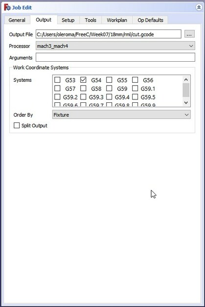
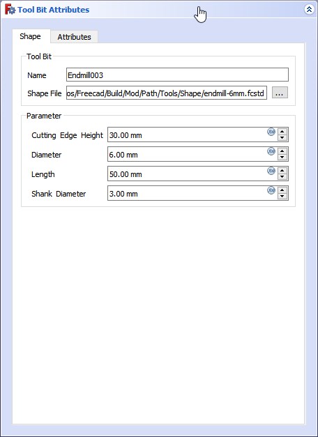
Job window allows creating a bounding box, select tool and output preferences. The Tool Bit Attributes is where the tool parameters are.
Profile settings allows for setting up the start depth and the final depth also choosing the path step down which is how deep the tool would cut into material.
From context menu I’m assigning holding tags and dog-bone dressups.
Machining
For the first try steps I’ve been using small milling machine present in our lab. It’s controlled with software called DrufelCNC. After setting up zero X Y Z program is ready for milling.

▼ Process have started

▼ Toolpath issue
Machine was milling 2 holes 1 layer at time resulting in long transitions between the holes.
Solution is that FreeCad toolpath job should be divided by operations and each hole should be separate operation to avoid transitions and save time.
▼ Zero shift
The outline job started normal but after first layer path zero shifted resulting ind misaligned outline.

▼ Other side

▼ The piece

After a while I got my hands to other machine that is bigger, stronger and has RichAuto controller so the pc is not required for milling.
▼ Starting the job
▼ Close-up
▼ After a while.

▼ Now it’s correct!
In FreeCad holding tabs for pieces to prevent moving while milling could be added as easy as dog bones using dressup from context menu.
Assembly
As the parts are cut they’re require cleaning and finishing in order to fit properly. Ideally this could be achieved using fillet bit but requires additional skills and time to setup and process. Instead, I was using just a send paper and sanding tool to clean and cut corners for fitting all together.
▼ Assembly start

Starting from the bottom and going up interlocking pieces it was quire tricky to assemble.
▼ After a while…

▼ And a while…

▼ And some more…
▼ And it’s done!

Honestly speaking I would not name this easy to assemble construction principle but it’s kinda fun and something like a quiz solving.
▼ It is not a chair!

▼ Not for sitting, only for observation!
▼ Usage example, only for observing!
