Computer-aided design
Starting this week I was exited to get into some cool CAD software. Since I have some experience in regular CAD my focus fell on tools like OpenSCAD, Antimony, Libfibve etc.
Code CAD
The main advantages of tools like mentioned above are that you building parametrized model from the start. Of course such tools not the best solution for rapid modeling or fast sketching, but they are very powerful and allowing to build code complex parametrized models.
Here is the curated list of Code CAD tools available out there.
OpenSCAD
OpenSCAD is a CAD tool with CSG (constructive solid geometry) mindset. That means it will do most tasks but lacking some easy to use tools like sweep or chamfer so you must use workarounds for this. Nevertheless, syntax in this program is easy to pick up even for users who have no coding experience like me.
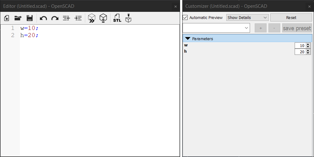
OpenSCAD have no GUI you’d expect to see in 3d modeling tool, instead it offers text editor to create and manipulate objects. Also, this program goes with a very handy tool called Customizer which adds easy to use controls for declared variables:
You can use text editor of your choice, program will just compile the code from name.scad on save.
Variables
First, let’s declare some variables:
w=10;
h=20;
t=5;
save and press F5 to load, as a result there are changes in customizer:
Objects
To add object you just need to declare it like this:
cube([18,18,18],false);
the first three numbers stand for dimensions in x,y,z and the false means that cube sides created with the corner lies on the origin at 0,0,0.
Customizer controls
Use variables to create an object and add sliders to the customizer to adjust variables:
w=10; // [50]
t=5; // [50]
h=20; // [50]

cube([w,t,h],false);
// [50] adds slider with the max value at 50 and min at 0.
Move object
To move object add translate() before cube() like this:
w=10; // [50]
t=5; // [50]
h=20; // [50]

translate([5,3,9]) cube([w,t,h],false);
this will move object origin by [x,y,z]
1D Array
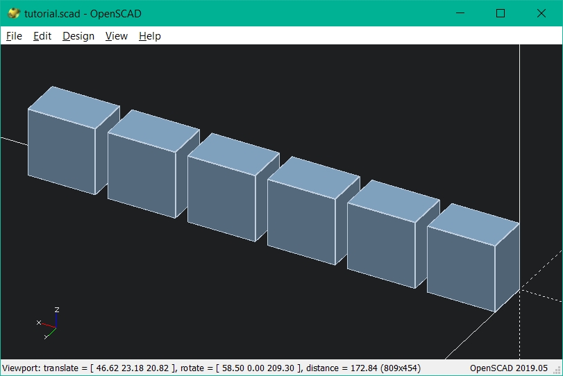
Now let’s use for() loop with translate() to make linear array of objects:
w=10; // [50]
h=20; // [50]
t=5; // [50]

for (i=[0:20:100])
translate([i,0,0]) cube([w,h,t],false);
loop for (i=[0:20:100]) will place i variable to translate() x parameter from 0 to 100 with increment number 20 and will create object array in x direction with distance 20 between the objects centers.
3D Array
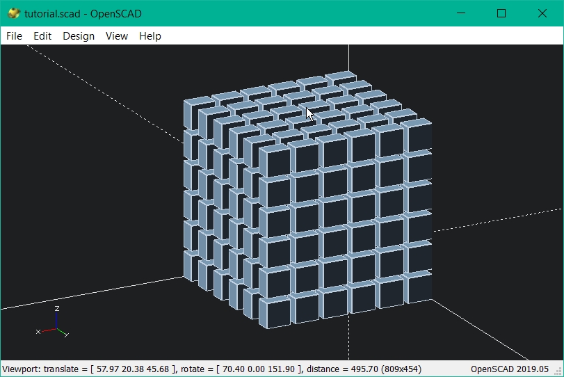
Now let’s expand this to 3 dimensions also using brackets to nest loops:
w=10; // [50]
t=5; // [50]
h=20; // [50]

for (k=[0:20:100]) { translate([0,0,k])
  for (c=[0:20:100]) { translate([0,c,0])
    for (i=[0:20:100]) {

      translate([i,0,0]) {cube([w,t,h],false);}
    }
  }
}
compiler will loop on each step placing objects corresponding to x,y,z that replaced by the current value of k,c,i.
Parametrization
Make this array adjustable with GUI controls:
w=10; // [50]
t=10; // [50]
h=10; // [50]

x=20; // [200]
y=20; // [200]
z=20; // [200]

xn=5; // [20]
yn=5; // [20]
zn=5; // [20]

for (k=[0:1:zn]) { translate([0,0,k*z])
  for (c=[0:1:yn]) { translate([0,c*y,0])
    for (i=[0:1:xn]) {

      translate([i*x,0,0]) {cube([w,t,h],false);}
    }
  }
}
Further parametrization:
w=10; // [50]
t=10; // [50]
h=10; // [50]

gap=0; // [20]

x=w+gap; // [200]
y=t+gap; // [200]
z=h+gap; // [200]

xn=5; // [20]
yn=5; // [20]
zn=5; // [20]

for (k=[0:1:zn]) { translate([0,0,k*z])
  for (c=[0:1:yn]) { translate([0,c*y,0])
    for (i=[0:1:xn]) {

      translate([i*x,0,0]) {cube([w,t,h],false);}
    }
  }
}
Now gaps between boxes are equal even if we change its size:
Use it!
Playing with this software for a while I’ve been able to create parametrized model of my final project’s part. In the next steps I’ll describe parameters that have been chosen and why.
Pin-disk array
en=100;
sm=100;
cc=1;//corection
g=0.2;

th=2; // [20]
pr=5; // [30]

gr=0;
shr=15; // [50]
ra=40; // [50]
hh=ra-shr; // [50]
hg=(pr+th)*2+gr*2;
ch=15 ; // [100]
cw=6; // [8]
dn=2;
pn=4;
pa=360/pn;
pi=ra-shr;
inc=2;
translate([0,0,((hg+g)*(dn+1))/2]){//shear line
  difference(){
    cylinder((hg+g)*(dn+1),shr,shr,true);


    translate([10,0,0])
    cube([shr*2,cw,(hg+g)*(dn+1)+cc],true);}
  }

module disk(){//DISK
    difference(){
      %cylinder(
        hg,
        ra,
        ra,
        true,
        $fn=sm
      );

      for (i=[1:1:pn]) {
        rotate([0, 0, pa*i]) {
          translate([shr,0,0]) cube([ch,cw,hg+cc]
            ,true);
          }
          rotate([0,90,0]) {
            rotate([pa*i, 0, 0])
            translate([gr,0,shr+hh/2])  cylinder(
              hh+cc,
              pr+g,
              pr+g,
              true,
              $fn=sm
            );
          }
        }

    cylinder(hg+cc,shr+g,shr+g,true );
      }


      for ( i=[1:1:pn]) {//pins
        a = i*pa; s = i*inc;
        rotate([0,0,a]){  rotate([0,90,0]) translate([gr,0,ra-(pi-s)/2])
          cylinder(
            pi-s,
            pr,
            pr,
            true,
            $fn=sm
          );
          rotate([0,90,0]);

        }
      }
}

for (i=[1:dn]) {//Disk array
      translate([0, 0, (hg+g)*i]) {
        disk();

      }
    }

*difference(){
      translate([0, 0, ((dn*(hg+g)+hg+g)/2)]) {cube(size=[en, en, dn*(hg+g)+hg+g], center=true);

      }
      cylinder(2000,ra+g,ra+g,true);

      for (i=[1:dn]) {//pinholes array
        rotate([0,90,0]) translate([(-hg-g)*i,0,ra+(en/2-ra+g)/2])
        cylinder(
          en/2-ra+3,
          pr+g,
          pr+g,
          true,
          $fn=sm
        );
      }
    }
Here is g parameter which is the gap between solid bodies. Since I have no experience in manufacturing and things can go wrong in many ways I decided to add adjustable tolerance, so I could tweak it easily:
The next variables are th which is the distance from pin edge to disk plate and pr that is the pin radius. These variables allow adjusting the disk height based on the pin diameter + the distance from the pin to the edge. Pins are the constraints of this detail because I think it’s preferable to buy them than to manufacture. The model have to be constrained by the parameters that will not vary in manufacturing process:
Parameters shr ra ch cw are responsible for adjusting dimensional parameters such as the shear line radius as well as the disk radius and rectangular cutouts size. Also, there are quantitative parameters pn and dn, they are responsible for controlling the number of pins and disks:
Notice, that pin length is automatically generated accordingly to pin quantity with increment value defined by inc variable.
2D software
Of course there are a lot more to CAD than just 3D tools. In the further weeks I will continue exploring new tools for 3D and 2D. You can go to next week and see I’m exploring InkScape, AutoCad, Gimp, Freecad and more.