Computer-controlled cutting
The machine
My host lab in Naples equipped with EPILOG laser cutter
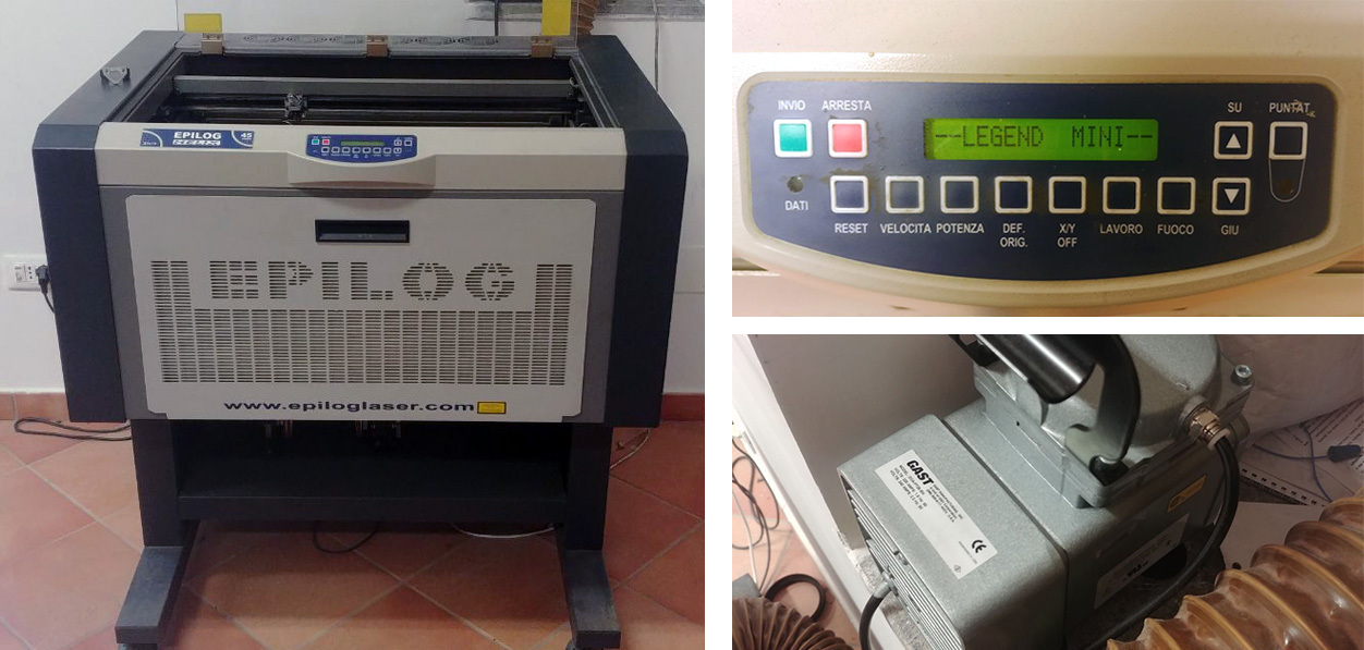
| power | working area | materials | filetypes |
|---|---|---|---|
| 45W | 610x457mm | PMMA/wood | AI/EPS/SVG |
Using vector image
Because the machine uses vector image as a path for cutting or raster for engraving, it is recognized by the pc as a printer. So with a proper driver any vector editor will do the job to output the vector image to the machine. I’m Using a CorelDraw to draw some shapes. The outputting vector image must have hairline linewidth which is less than 0.01 mm. The lines must be continious and have no intersections, overlaps or double lines and the sheet size should be equal to the laser table size.
Focusing the laser
Laser is need to be focused to achieve desired kerf and cutting performance. For this I’n using small metal triangle piece that mounts on the laser head. The focal point is where the piece touching the surface. Placing it on the top and manually moving laser head, I’m checking the deviation around the surface by looking if the triangle is pushed by the surface or of there is a gap underneath. Then, I’m trying to adjust the height of the table to average the error.
Turning on air blower and exhaust
While lasering, burn products have to leave enclosed space of cutter through exhaust also if cutting easy inflammable materials stream of compressed air must be applied to blow off the fire and prevent inflammation.
Adjusting the right values
As the vector image is ready, we need to configure laser cutter using Epilog engraving preferences. To cut we use vector, to engrave - raster. There is combined mode to both but for now I’m interested only in cutting. To achieve desired cutting result I’ve adjusted speed/power/frequency values starting from reference point of 30/40/500 correspondingly.
The main preferences are in General tab. For cutting we use vector, and for engraving raster.
Cutting tests
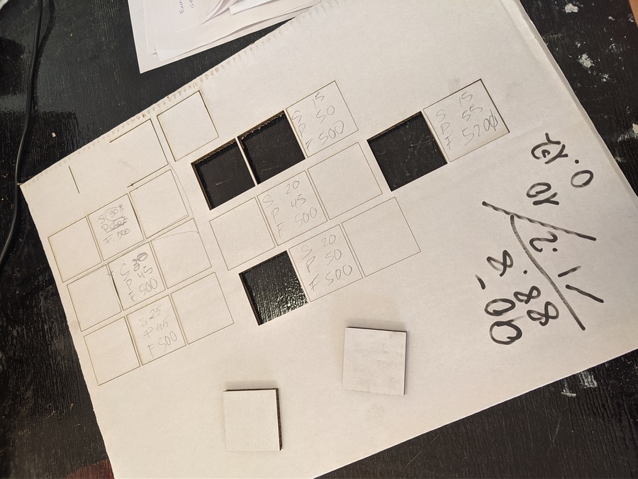
Finding the kerf
Kerf is the amount of the material that is burned out by laser, it depends on material properties as well as on laser settings. To measure it we will need to cut something and then compare resulting dimension to model values. Because every material has some imperfections and result may vary by some degree averaging the mistake have to be done. To do this, cut a ladder with equally segmented rectangles placed on each other.
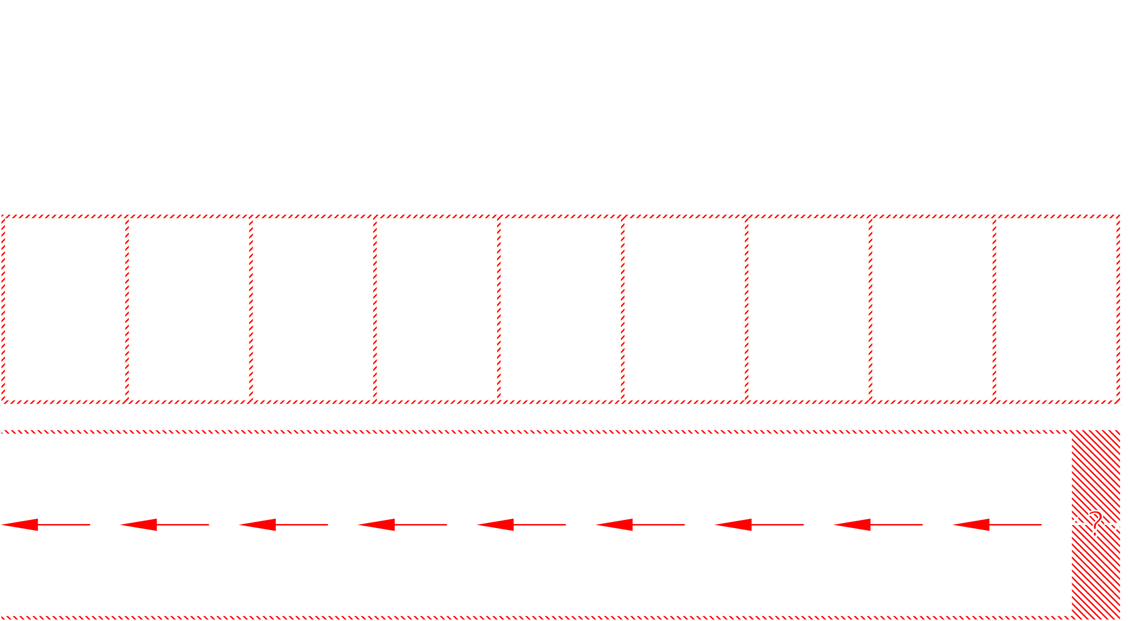
The hatched area is burned material, and it’s width equal to the kerf value. So if I’m cutting out a test and measure this dimension, I should be able to know exact value. To reduce the error due to material imperfections and measurement instrument limitations wee need to average the kerf by simply shifting all rectangles and make them touch each other. The resulting gap is the sum of all kerfs in X axis which is. Measuring this gap and dividing it by the number of vertical cuts resulting in averaged kerf value that can be used to achieve precision.
Assignment
With the third assignment I’ve tried to create modular 2D shape that would be assembled into some continuous structure. In the past weeks I’ve noticed many tools I’d like to try and for this assignment I chose FreeCAD as a modeling tool, Inkscape as a vector editor and Deepnest for part nesting.
Construction-kit modelling
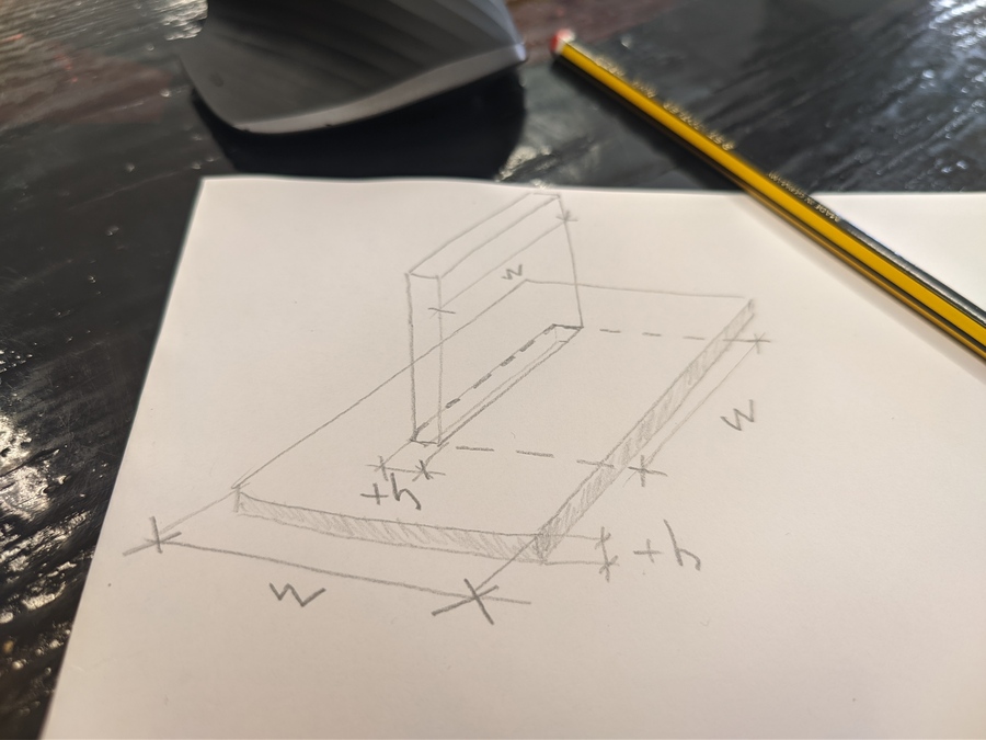
I’ve got an idea, what if to cut a rectangle and a hole in it which will correspond to peace width and material thickness? We than would be able to fit same peace in that hole. Now taking the initial idea further. I’s it possible to make these intersected pieces locked in some way? Combining rectangular and circular profiles for a cutout and making symmetrical slots along longer side it is possible. The distance between slots will correspond to circle diameter and the slot width to material thickness which already declared as width wi and thickness th. Now the inner part would be able to fit in, translate to the slot position and rotate to lock.
I chose FreeCAD because it has very good parametric tools and also I wanted to try to assemble resulting pieces interactively. For assembly, I used Assembly4 workbench that have to be installed manually with FreeCAD Addon manager.
You could see the command sequence marked with ▼ symbol
Init
further instructions apply only for FreeCAD version 0.19
▼ Create a new file in FreeCAD and call it piece.
▼ Switch to Spreadsheet workbench
▼ Create a new spreadsheet.
▼ Open Spreadsheet ▼ add some variables and add cell aliases by typing name in Alias: field and pressing Enter.
Sketching
▼ Back to model. Switch to Assembly4 workbench, then ▼ create new Assembly4 model, toggle it active ▼ create a new body ▼ create a new sketch and choose XY_Plane001.
▼ Create two intersecting rectangles and trim some edges like this:
▼ And make it symmetrical
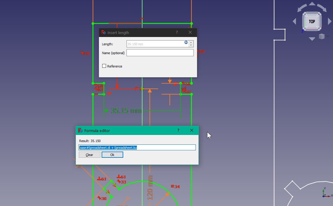
▼ From this step I’m adding dimension constraints to using variable aliases defined in Spreadsheet.
Now creating joint hole-fit profile: ▼ Create a point in the sketch and place it on the Y axis ▼ create a rectangle in the sketch ▼ delete horizontal and vertical constraints
▼ create a perpendicular constrain between two adjacent lines
▼ constrain width and height of a rectangle using width and thickness variables
▼ fix a length of a distance between rectangle center point and piece adjacent edge
▼ fix the angle between rectangle long side and piece adjacent edge.
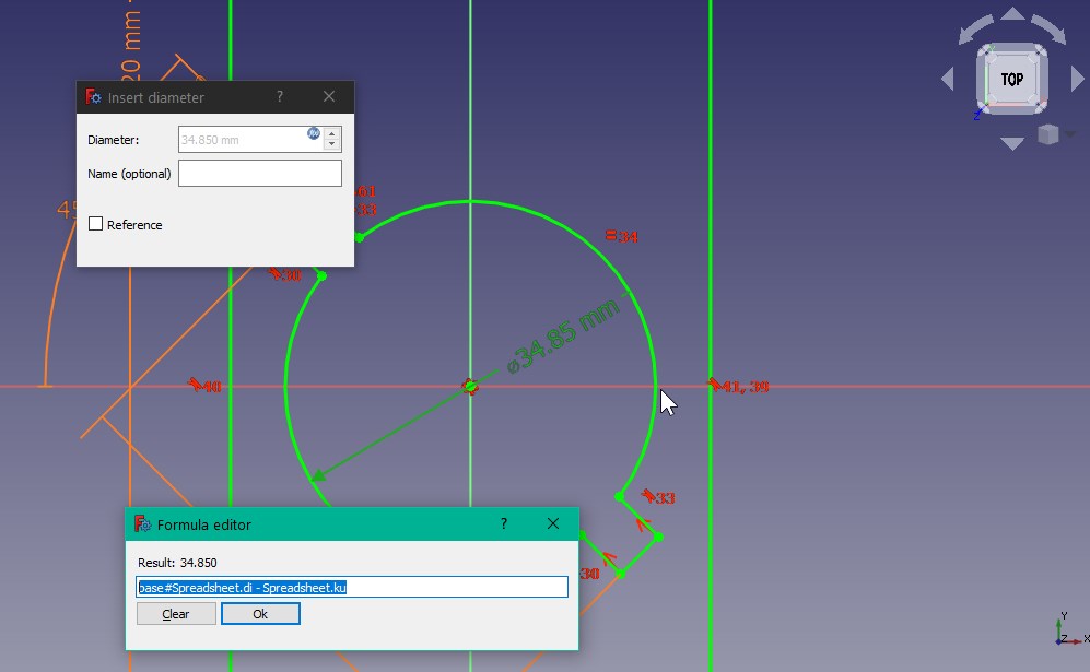
▼ Create a circle inside rectangles center point ▼ trim inner edges
▼ Fix the diameter of the circle
▼ create symmetric geometry with respect to x axis
◉ Re constrain every dimension by formula according to previous steps only inverting an parameter to -an
▼ fix a length of mirrored circle’s center points
▼ Close the sketch ⬤ Sketch is ready for creating a body
Creating a body
▼ Close the sketch
▼ go to tasks
▼ create a pad
▼ assig th alias to length
⬤ Geometry is done.
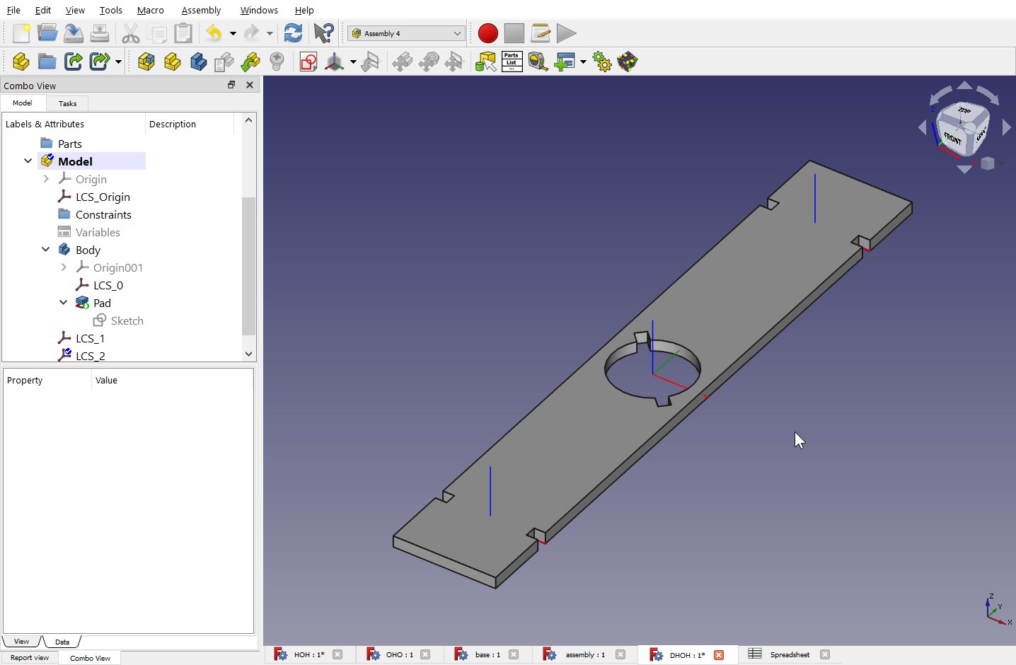
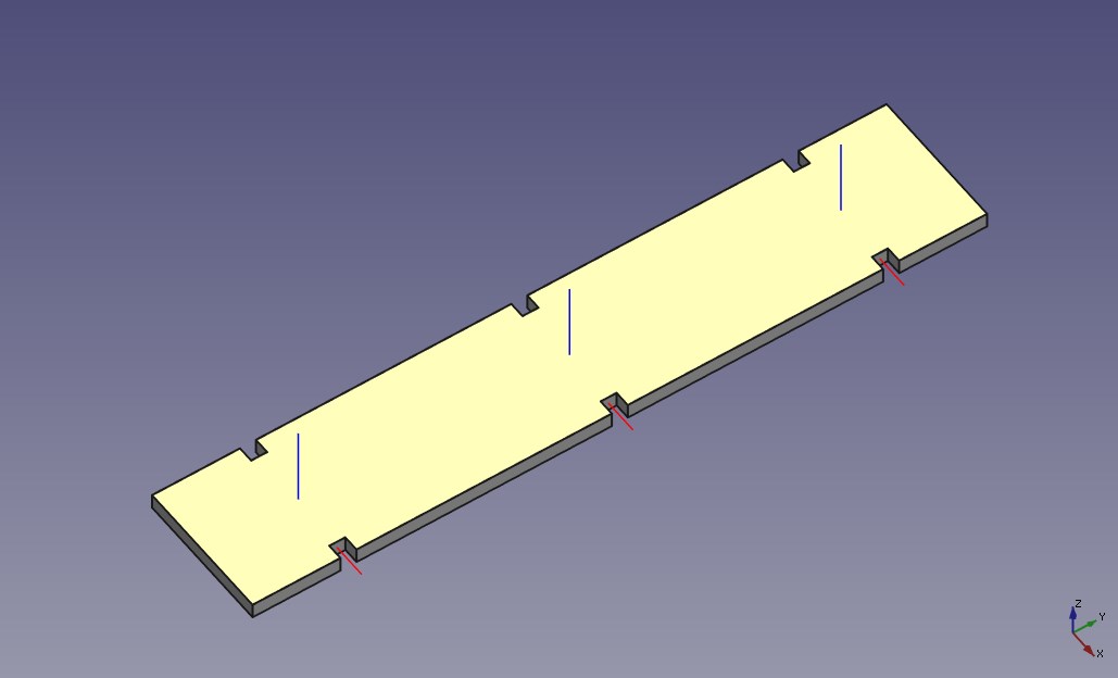
Attaching coordinate systems
▼ Select aseembly4 model
▼ go to assmbly4 workbench
▼ create new coordinate system
▼ select faces parallel to front view
▼ choose Inertial CS in Attachment mode
▼ specify Attachment Offset in y-direction to sp/2
▼ press OK
◉ Repeat last sequence inverting sp/2 to -sp/2
▼ Select LCS_1 and look for Attachment... property
▼ Click ... button
▼ Specify rotation Around x-axis to 90°
▼ Press OK
◉ Repeat last sequence with LCS_2
⬤ Body is ready to be assembled.
Assembly
Working in freecad I wanted to push it as close to Fusion performance as possible. It’s interesting if this program is able to compete with commercial counterparts. In case of Fusion, I was able to create assembly not even looking into tutorials, just clicking and playing around for a while. With FreeCad it’s not the case, the model could fail in different ways and sometimes the changes could be destructive in opposite to un-destructive Fusion workflow. Working in Freecad requires more attention and patience. Of course, it has benefits of its own, for example, in opposite to Fusion it’s a standalone program and doesn’t require internet. Also, as any open source it’s highly customizable.
Additional steps are required in order to achieve good parametrised assembly. The piece that was made can’t create closed structure and more pieces are needed to close it. FreeCad utilizes Spreadsheets to parametrize a model and each cell could be linked to other in the same file or between files. Assembly model may consist from different pieces, but they must share some parameters that are essential for correct placement. Unfortunately spreadsheets cell links are not updated automatically and if using this kind of linking would require updating changes in each file manually. There is another method of linking parameters between files in FreeCad that allows to update all assembly pieces simultaneously. Linking in this way happens inside the sketch. It’s more tedious process than in spreadsheet but at the end more interactive model could be achieved. So, in order to link all the pieces together additional steps are required:
▼ Go to file location
▼ rename the piece.FCStd to base.FCStd
▼ copy file and name it OHO.FCStd
Here I’m using letters as a graphical representation of piece configuration. This allows to navigate easier between different pieces while assembling.
▼ open base.FCStd in FreeCad
▼ open OHO.FCStd ▶ delete Spreadsheet form model’s Combo View
After this step FreeCad’s console would scream about unresolwed dependencies.
▼ go to initial sketch
▼ reassign each constraint appending base# at the beginning of each function
Here we are telling FreeCad to look for the parameter inside a file with the name
bse. The endresult would look something likebase#Spreadsheet.th
Now we have two pieces, one is a reference for another to get parameters from. The additional pieces would require the same steps for linking.
▼ copy OHO.FCStd ▶ rename to HOH.FCStd
▼ open HOH.FCStd ▶ open the sketch
▼ delete the sketch contents
▼ reproduce the shape
▼ delete inner rectangle’s vertical/horisontal constraints
▼ Trim edges as follows
▼ link dimensions to base.FCStd‘s spreadsheet
△ close the sketch
△ link the pad thikness to base#Spreadsheet.th
△ link the distance between coordinate systems to base#Spreadsheet.dis
⬤ Done!
Assembly4 workbench provides easy assembling workflow, but it is very sensetive to selection made in Combo View. Creating coordinate system in wrong selection would lead program to fail inserting parts or misbehave in different ways. So, in order to achieve good parametrical model, below steps must be preserved in the exactly same sequence as below:
▼ open all pieces in FreeCad
▼ create new file and name it Assembly
▼ create new Assembly4 model, toggle it active
▼ insert a link to a part
▼ chose base#Model
👁 look for Attach to** ▶ chose Parent Assembly
▼ chose LCS_Origin in linked and parent part
▼ press ++”Rotate Y +90°”++ ▶ click OK
◔ Repeat 3 lines from above attaching to base and LCS_1
▼ insert one more OHO piece ▶ attach to OHO coordinate system
👁 look forAttachment property ▶ press ... button
▼ ajust rotation Around y-axis: to 45°
◔ repeat the sequence building the shape
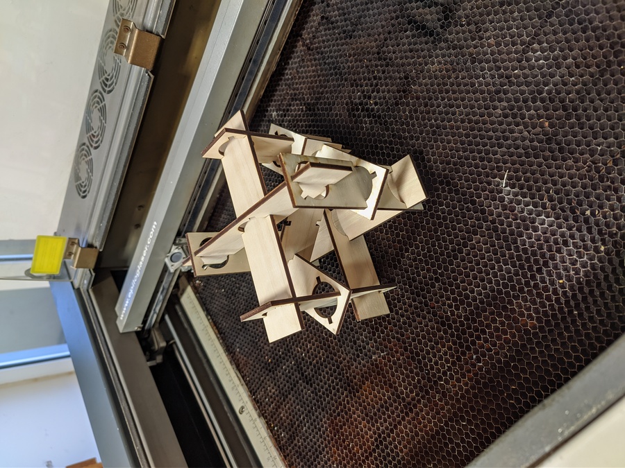
From this point additional pieces are required to complete the structure. The resulting assembly is essentially a cube with an edge that equals to spreadsheet parameter sp, which is spread between piece’s connection center points. The remaining pieces are the diagonals of this cube’s side and its spread could be calculated easily using FreeCad’s expressions.
▼ go to base spreadsheet
▼ add expression =sp/cos(45) ▶ assign alias dis to the expression’s cell
▼ rename HOH.FCStd to DHOH.FCStd
▼ open DHOH.FCStd‘s sketch ▶ replace sp dimension with dis
◉ HOH diagonal piece is finished
▼ insert DHOH piece into assembly
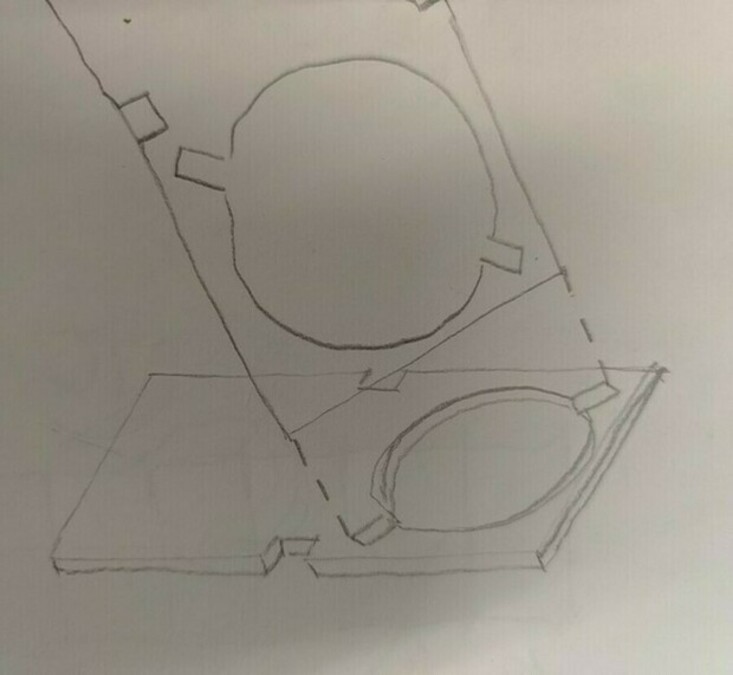
While modelling the initial piece, it was not clear what are the angle of the circles fit-in cutouts would be needed in order to be able to assemble it. From resulting model we can see that the angle suitable for this configuration is 45°. Other angles would require producing additional pieces to fit in every component in place. From the below gif, you can see that cutouts profiles are perfectly aligned locking pieces to come through. Increasing or decreasing the angle would lead cutout to interfere with outer boundaries destroying integrity of the body. Changing the angle in one way would make the distance from cutout to the edge to thin on side pieces, in other way we would see the same result on diagonals.
The shape is lacking one final piece to gain structural rigidity, locking HHH shape.
▼ Fit in the final piece
Now we can test our model. To adjust the assembly to different parameters, just change the base spreadsheets’ value and then, in assembly viewport press F5
Cutting
Now let’s cut the shape, but before, we need to make a vector image to then feed it into laser cutter. The cutting file could be linked to base and updated with the spreadsheet changes. To achieve this:
▼ Create new FreeCad file named cut ▶ open the file
▼ hold Ctrl ▶ drag the sketch from DHOH to cut
▼ select the sketch in cut ▶ press Space on the keyboard
▼ delete XY_Plane001 from cut file
This will copy the sketch to created file and toggle its visibility on and. The sketch copies with support plane it attached to. We don’t need these planes for the resulting image so just delete it.
◔ repeat for HOH and DHHH
▼ Position the sketches side by side using Placement property
Kerf adjustment
If we take the vector image with model dimensions and feed it into laser cutter, the resulting piece size would be slightly off the designed one by amount of the kerf depending on the profile. If it’s a hole, dimension would increase from each side by 1/2 of the kerf. To adjust cutting dimensions, wee need to encounter also fitting aspects of the piece. If I want a piece to come into hole other more freely, I would need to make either hole wider or the piece thinner. If I want to make fitting more sturdy, I would set dimensions equal. This what is called the interference, and would lead to tight fit. Harder the material, the harder would be the fitting, or it could even be impossible to do it without a tool.

▲ The red hatch is a removed part of the piece and the white line is the resulting dimension.
▲ Here, I’m adding the kerf to dimension, so the output piece would match the initial model.
▲ The same for this dimension, this I want to be the same as in model.
▲ Here is the hole, so the dimension would be increased by kerf. That means i need to substract it from initial size.
The kerf ajustment depends on the dimension constraint. So, if I have constrained a circle by radius instead of diameter, this would require me to substract 1/2 of a kerf.
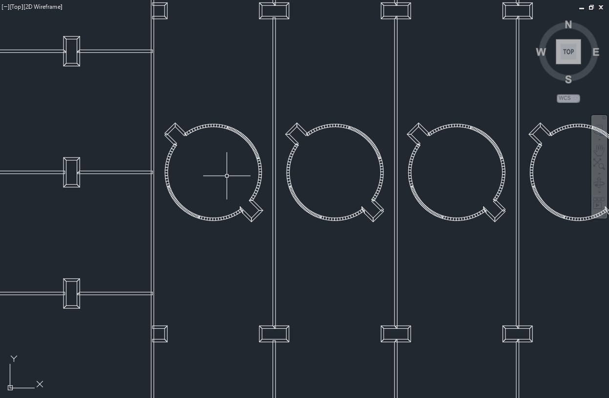
Using deepnest to nest parts
To cut with laser efficiently it’s a good practice reducing the overall path length, this could save cutting time and use material more efficiently. Placing profiles side by side and overlapping adjacent edges could be not an easy task especially when cutting multiple shapes of different configurations. Finding the best fitting layout could be time consuming for human and sometimes, depending on complexity, even for program.Though I have not so many parts and outer profile is essentially a rectangle, I wanted to try Deepnest for part nesting.
▼ Import vector image to Deepnest ▼ choose the quantity of each profile ▼ press ➕ button ▼ add rectangle with material’s sheet size ▼ press Start nest ▼ export as the satisfied result is achieved
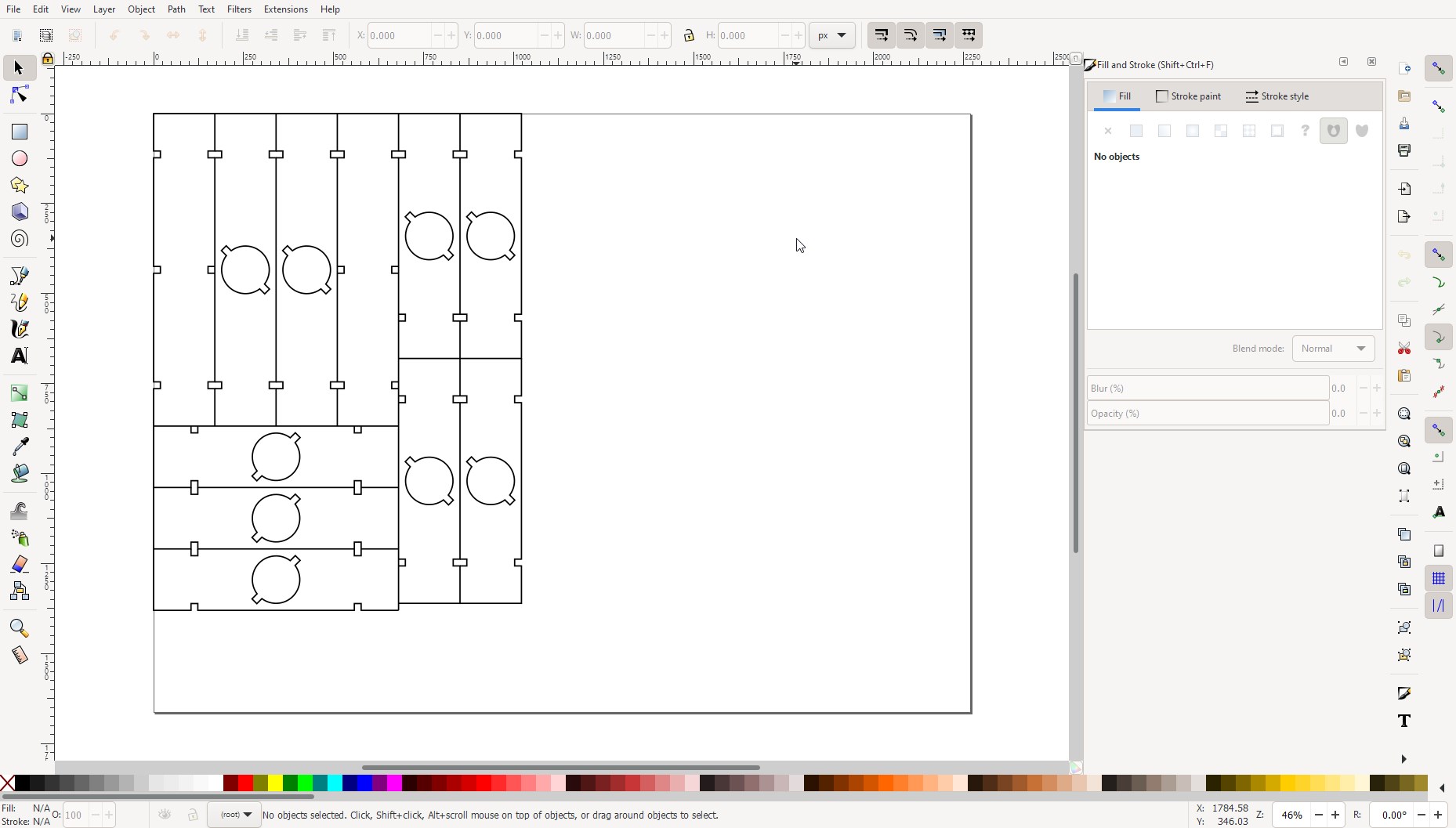
Print setup
▼ Trying to export into .dxf resulted outputting strange double lines
▼ Exporting to .svg to use in InkScape
Starting the job
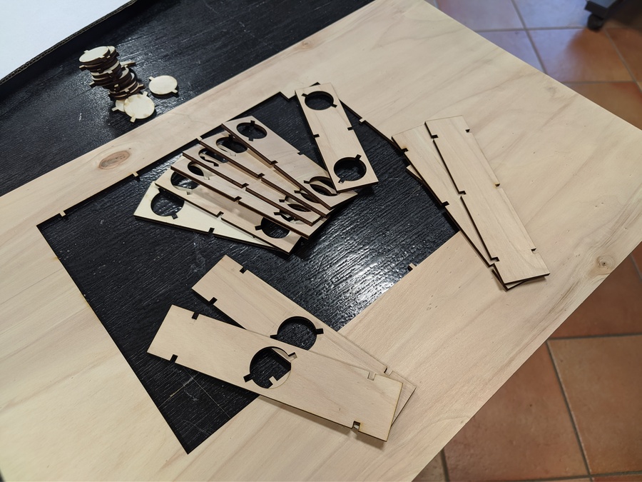
Resulting pieces
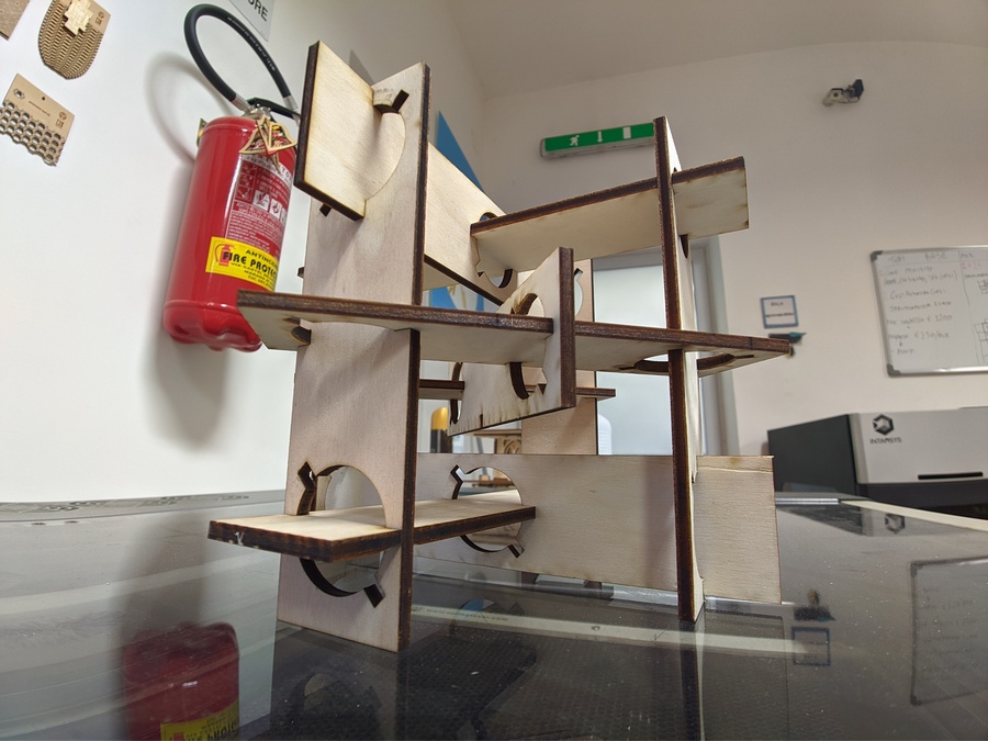
Construction-kit assembly
Vinyl cutter

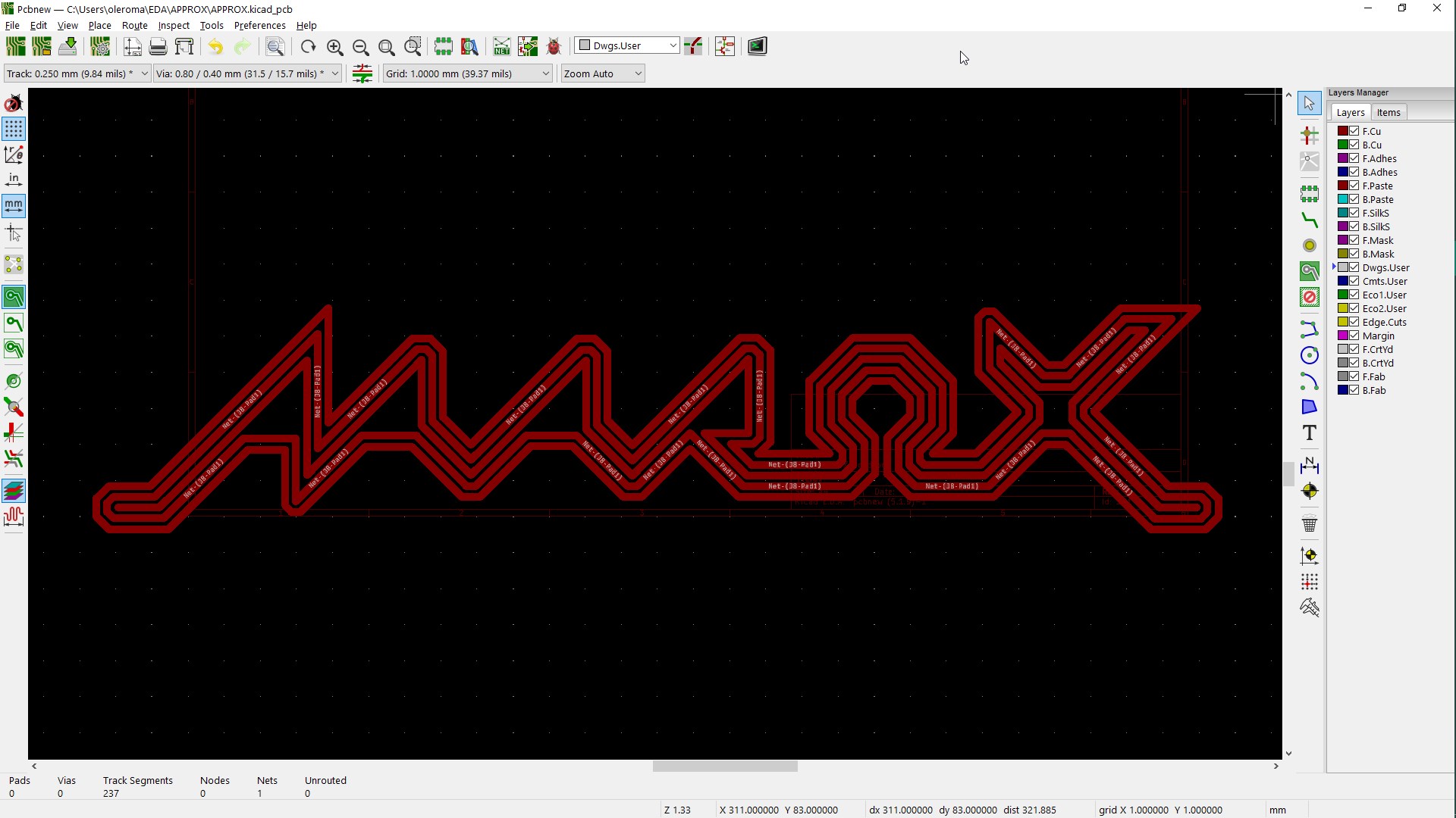
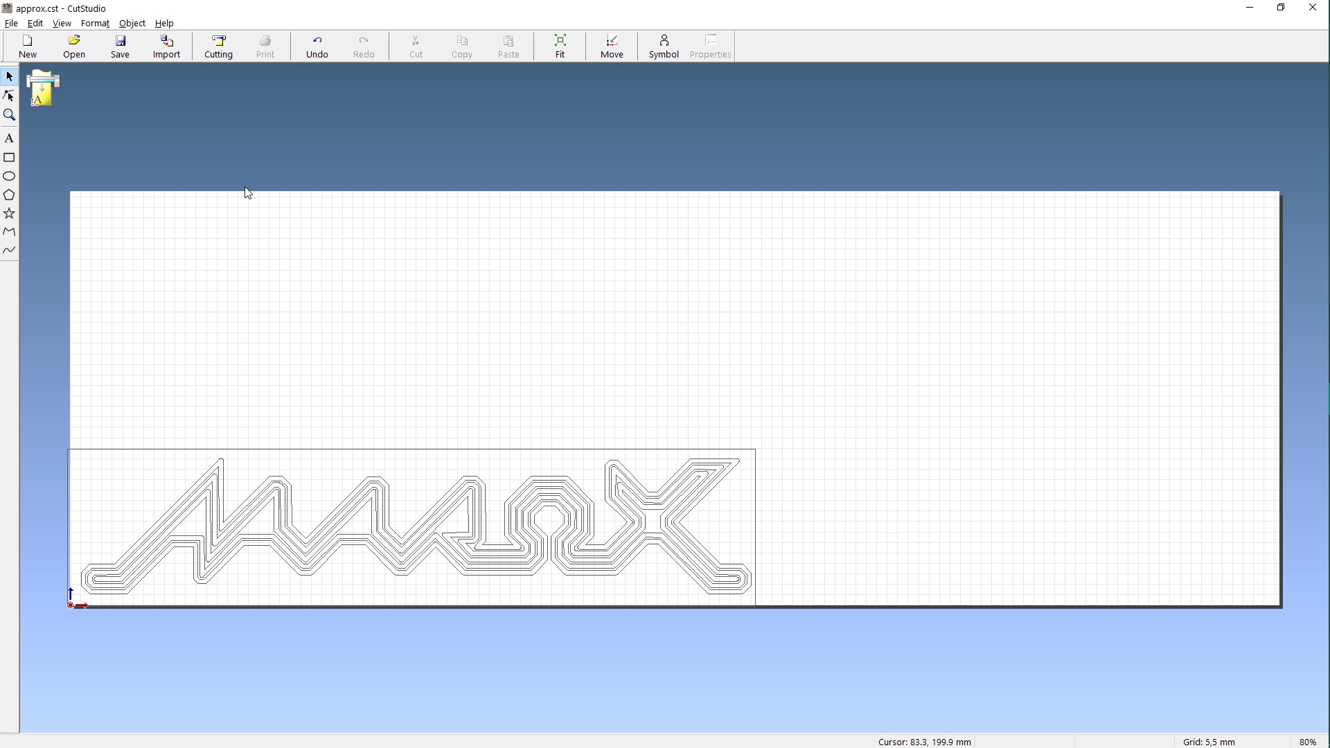
I was thinking, if you can design traces in InkSkape so why not designing graphical logo in KiCAD? It actually has some cool features that allow you to design multiple continuous lines with constrained clearance between them. Assigning different net-list values to line (trace, track) allows you to freely draw lines with mouse that are spaced equally and are continuous. With adjusted grid and 45 degree constraints designing stylized logo becoming really interesting!
Roland GX-24
The machine is good but for some reason the software was refusing to accept files exported from Inkscape of Gimp and instead accepted only after re-exporting it through Paint.
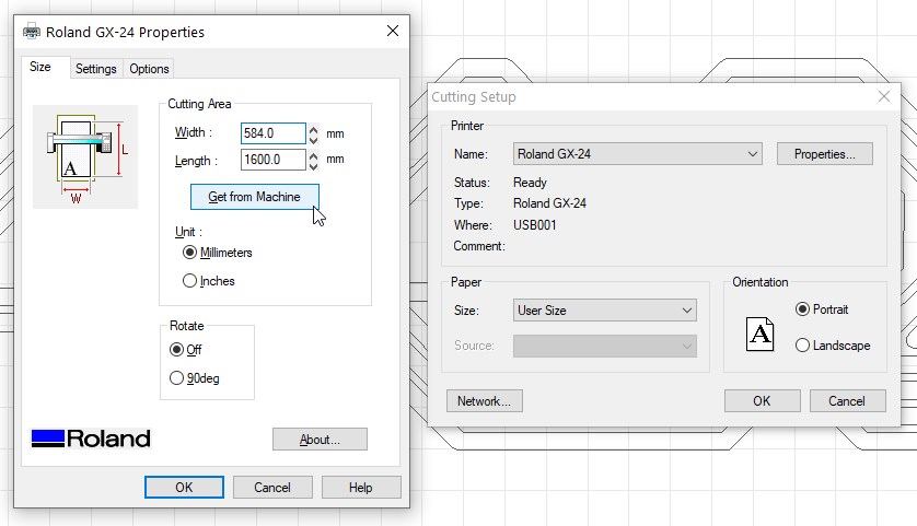
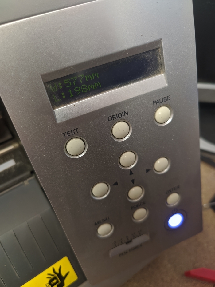
Rigth after installing the paper this machine is able to measure cutting area and output it to the software with few clicks.
As the piece is placed and aligned we could send the job and start cutting.
The process is smooth and fast.
Looking into the picture you’d notice that all the letter thickness is actually an offset around one single line, and that mean all the black areas are continuous and could be easily removed with one move! This is the result of KiCad design rules, and I’m pretty happy with outcome achieved.
To transfer the sticker to the target surface I’ve used masking tape and it did the job pretty well!
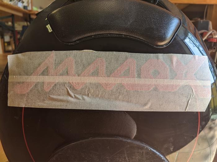
Now the logo is ready to ride!