15. InterFace and Application programming
This week I worked on making a PC software that interfaces with the PCB I made for the networking week.
Research
After taking a look at the material and software suggested by the FabAcademy website, and asking around I have decided to build the software using Python with the PyQt5 library, as the PyQt5 has an additional studio software that helps build more beautiful interfaces in a drag and drop environment, and Python should be easy to use moving from C.
Python
first steps into python
The first thing to do is to learn Python as I have never used it before, I prefer video content for new topics so I did some search and watched this toturial on Python, moving to python from C it was a fairly easy transition, but I have always found it hard to deal with objects and object-oriented programming and python is mostly all objects so I have my fair share of errors on the way.
first project
Now after I have watched almost 3 hours of the tutorial I felt it is enough to try and start using the language, I started with a PyQt5 tutorial project playlist from tech with tim to understand how the interface is built, and get to know the library and its functions.
I usually use Linux subsystem for windows 10 for coding, but since I am building a GUI interface and recall Neil’s interface app in input week) did not work in it I did my work in Windows 10 PowerShell and vs code.
I already had the Python3.9 environment running on my PC when I was working on the input week, I had downloaded it from windows 10 store, it can be downloaded from Python official website too.
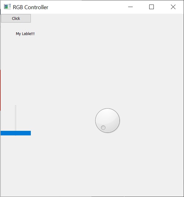
Here is the first PyQt5 project I made following the tutorial above, I have added comments to make the code more clear.
#import needed libraries
from PyQt5 import QtWidgets
from PyQt5.QtWidgets import *
from PyQt5.QtCore import *
from PyQt5.QtGui import *
import sys
from sys import argv

#define a class responsible for the gui interface
class MyWindow(QMainWindow):
    def __init__(self):#this function runs automaticly when a new object is defines
        super(MyWindow, self).__init__()
        self.setGeometry(200, 200, 600  , 600)
        self.setWindowTitle("RGB Controller")
        self.initUI()

    def initUI(self): #design UI elements
        self.label = QtWidgets.QLabel(self)     #make a label
        self.label.setText("My Lable!!!")       #name the label
        self.label.move(50 , 50)                #position the label

        self.b1 = QtWidgets.QPushButton(self)   #make a button
        self.b1.setText("Click")                #select button text
        self.b1.clicked.connect(self.clicked)   #connect button to a function

        self.Dial = QtWidgets.QDial(self)   #make a Dial
        self.Dial.setGeometry(300, 300, 100  , 100)#set the size and location of the dial

        self.Slider = QtWidgets.QSlider(self)   #make a slider
        self.Slider.setGeometry(0, 300, 100  , 100) #set the size and location of the slider


    def clicked(self):  #funcution for when the button is pressed
        self.label.setText("you pressed the button")
        self.update()

    def update(self):
        self.label.adjustSize()


def window():
    app = QApplication(sys.argv)
    win = MyWindow() #define an object window

    win.show() # show the window
    sys.exit(app.exec_())

#MainCode
window()
Interface with a PCB
Now that I have some knowledge about python and PyQt5, its time to make a python code that talks to a PCB, I used the PCB that I had made in the networking week it has a UART interface that I will be using to make a GUI that controls the RGB on the board.
first I had to try and connect python to the serial interface of the PCB, for that I used this tutorial.
after I tried it and made sure it works, I added a simple modification on the python code so that the user gives the com port and the serial communication speed before it runs.
Python Code
# Importing Libraries
import serial
import time
import serial.tools.list_ports

#list availabe com ports
ports = list(serial.tools.list_ports.comports())
for p in ports:
    print(p)

#let user pick com port
boardCom = input("Enter com, example'com3' :")

#let user pick com speed
COMBaudRate = input("Enter communication speed, example'115200' :")

#initialize communication
PCB = serial.Serial(port=boardCom.upper(), baudrate=COMBaudRate, timeout=.1)

def write_read(x):
    PCB.write(bytes(x, 'utf-8'))
    time.sleep(0.05)
    data = PCB.readline()
    return data

while True:
    num = input("Enter a number: ") # Taking input from user
    value = write_read(num)
    print(value) # printing the value
Arduino Code
int x;

void setup() {
  Serial.begin(115200);
  Serial.setTimeout(1);
}

void loop() {
  while (!Serial.available());
  x = Serial.readString().toInt();
  Serial.print(x + 1);
}
Final results
Now its time to work on the week’s assignment, building up my code step by step, testing, and making sure every element works well, I used this tutorial box layout to get the interface to scale if the window size changed by the user, and this [tutorial] to make the Arduino code to read a string and break it apart to get the instruction, for example, the python code sends this string to the PCB <BLUE, 100>, the PCB will read < and understand that its a communication initializer, read the first work till the , symbol, saves it in a string then reads the second word… so and so, thill it reaches the > symbol as a communication ending, sends a replay, and end the string reading.
here is a video running the code, and down below are both the python and Arduino codes.
Assignment python code
# add needed libraries
import serial
import time
import serial.tools.list_ports

from PyQt5.QtWidgets import QDialog, QDial, QHBoxLayout, QVBoxLayout, QApplication, QSpinBox
from PyQt5.QtGui import QIcon
import sys

#get data from user to run serial commuinication correctly
#list availabe com ports
ports = list(serial.tools.list_ports.comports())
for p in ports:
    print(p)

#let user pick com port
boardCom = input("Enter com, example'com3' :")

#let user pick com speed
COMBaudRate = input("Enter communication speed, example'9600' :")

#initialize communication
PCB = serial.Serial(port=boardCom.upper(), baudrate=COMBaudRate, timeout=.1)

#function to send data to PCB and get a responce
def write_read(x):
    PCB.write(x)
    time.sleep(0.05)
    data = PCB.readline()
    return data

#set main window class
class Window(QDialog):
     # function that runs automaticly when defining a new object to this class
    def __init__(self):
        super().__init__()

        title = "Dial pplication"
        top = 40
        left = 200
        width = 450
        height = 300

        icon = "icon.png"

        self.setWindowTitle(title)
        self.setGeometry(top, left, width, height)
        self.setWindowIcon(QIcon(icon))
        self.InitUI()

    def InitUI(self): # function to initlize window widgets
        #define RGB dials
        self.dialRed = QDial(self)
        self.dialRed.setNotchesVisible(True)
        self.dialGreen = QDial(self)
        self.dialGreen.setNotchesVisible(True)
        self.dialBlue = QDial(self)
        self.dialBlue.setNotchesVisible(True)

        #define RGB spin
        self.spinRed = QSpinBox(self)
        self.spinGreen = QSpinBox(self)
        self.spinBlue = QSpinBox(self  )

        #define layout, 2 horizantal, one for dials, and the other for spins
        self.hbox = QHBoxLayout()
        self.hbox2 = QHBoxLayout()
        self.vbox = QVBoxLayout()

        #add 2 horizantal layouts to the vertical layout
        self.vbox.addLayout(self.hbox)
        self.vbox.addLayout(self.hbox2)

        # add dials and spins to the horizantal layouts
        self.hbox.addWidget(self.dialRed)
        self.hbox.addWidget(self.dialGreen)
        self.hbox.addWidget(self.dialBlue)
        self.hbox2.addWidget(self.spinRed)
        self.hbox2.addWidget(self.spinGreen)
        self.hbox2.addWidget(self.spinBlue)

        #set vertical layout for the main window
        self.setLayout(self.vbox)

        #link dials to spins and set ranges to 255
        self.dialRed.valueChanged.connect(self.spinRed.setValue)
        self.spinRed.valueChanged.connect(self.dialRed.setValue)
        self.dialRed.setRange(0, 255)
        self.spinRed.setRange(0, 255)

        self.dialGreen.valueChanged.connect(self.spinGreen.setValue)
        self.spinGreen.valueChanged.connect(self.dialGreen.setValue)
        self.dialGreen.setRange(0, 255)
        self.spinGreen.setRange(0, 255)

        self.dialBlue.valueChanged.connect(self.spinBlue.setValue)
        self.spinBlue.valueChanged.connect(self.dialBlue.setValue)
        self.dialBlue.setRange(0, 255)
        self.spinBlue.setRange(0, 255)

        #link dials to functions
        self.dialRed.valueChanged.connect(self.redValue)
        self.dialGreen.valueChanged.connect(self.greenValue)
        self.dialBlue.valueChanged.connect(self.blueValue)

    # fuction to act when the red dial is changed
    def redValue(self):
        num = self.dialRed.value()
        dataToSend = "<RED," + str(num) + ">"
        value = write_read(dataToSend.encode())
        PCB.write(dataToSend.encode())
        print(value)

    # fuction to act when the green dial is changed
    def greenValue(self):
        num = self.dialGreen.value()
        dataToSend = "<GREEN," + str(num) + ">"
        value = write_read(dataToSend.encode())
        PCB.write(dataToSend.encode())
        print(value)

    # fuction to act when the blue dial is changed
    def blueValue(self):
        num = self.dialBlue.value()
        dataToSend = "<BLUE," + str(num) + ">"
        value = write_read(dataToSend.encode())
        PCB.write(dataToSend.encode())
        print(value)

# function to start the window object
def window():
    app = QApplication(sys.argv)
    window = Window()
    window.show()
    app.exec()


#MainCode
window()
Assignment Arduino code
#define redPin 5
#define greenPin 6
#define bluePin 3

const byte numLEDs = 2;
byte ledPin[numLEDs] = {12, 13};
unsigned long LEDinterval[numLEDs] = {200, 400};
unsigned long prevLEDmillis[numLEDs] = {0, 0};

const byte buffSize = 40;
char inputBuffer[buffSize];
const char startMarker = '<';
const char endMarker = '>';
byte bytesRecvd = 0;
boolean readInProgress = false;
boolean newDataFromPC = false;

char messageFromPC[buffSize] = {0};
int newValue = 0;


struct RGB{
      byte r;
      byte g;
      byte b;
    };


void setup() {
  Serial.begin(9600);   // Initiate a serial communication
  //Serial.setTimeout(1);

  pinMode(redPin, OUTPUT);
  pinMode(greenPin, OUTPUT);
  pinMode(bluePin, OUTPUT);

  digitalWrite(redPin, HIGH);
  digitalWrite(greenPin, HIGH);
  digitalWrite(bluePin, HIGH);

}

void loop() {
// put your main code here, to run repeatedly:
  getDataFromPC();
  replyToPC();
  updateValue();
  replyToPC();

}

//=============

void getDataFromPC() {

    // receive data from PC and save it into inputBuffer

  if(Serial.available() > 0) {

    char x = Serial.read();

      // the order of these IF clauses is significant

    if (x == endMarker) {
      readInProgress = false;
      newDataFromPC = true;
      inputBuffer[bytesRecvd] = 0;
      parseData();
    }

    if(readInProgress) {
      inputBuffer[bytesRecvd] = x;
      bytesRecvd ++;
      if (bytesRecvd == buffSize) {
        bytesRecvd = buffSize - 1;
      }
    }

    if (x == startMarker) {
      bytesRecvd = 0;
      readInProgress = true;
    }
  }
}

//=============

//=============

void parseData() {

    // split the data into its parts

  char * strtokIndx; // this is used by strtok() as an index

  strtokIndx = strtok(inputBuffer,",");      // get the first part - the string
  strcpy(messageFromPC, strtokIndx); // copy it to messageFromPC

  strtokIndx = strtok(NULL, ","); // this continues where the previous call left off
  newValue = atoi(strtokIndx);     // convert this part to an integer


}

//=============

void replyToPC() {

  if (newDataFromPC) {
    newDataFromPC = false;
    Serial.print("<Msg ");
    Serial.print(messageFromPC);
    Serial.print(" recieved");
    Serial.print(">");

  }
}

//============

void updateValue() {

   // this illustrates using different inputs to call different functions
  if (strcmp(messageFromPC, "RED") == 0) {
    analogWrite(redPin, (255 - newValue));
  }

  if (strcmp(messageFromPC, "GREEN") == 0) {
    analogWrite(greenPin, (255 - newValue));
  }

  if (strcmp(messageFromPC, "BLUE") == 0) {
    analogWrite(bluePin, (255 - newValue));
  }
}