4. Computer controlled cutting
This week is about computer-controlled cutting, I will be trying the trotec speedy 300, and the roland bn-20 desktop vinal cutter.
laser cutter
Laser cutting is a thermal operation, where the laser beam is focused on a point and creates a kirf there. moving the focused beam is the operation of laser cutting.
the kirf is the material that got melted or burnt because of the laser, understanding the keft allows for perfect dimension cut parts.
Read this article for more detials about laser cutting.
Trotec speedy 400
In this section, I will explain how to operate the trotec speedy 400 laser cutter. before learning how to turn the machine on, make sure you know how to turn it off, locate the emergency push button and try it to make sure it shuts the machine off, things can catch fire so make sure to have a fire extinguisher around.
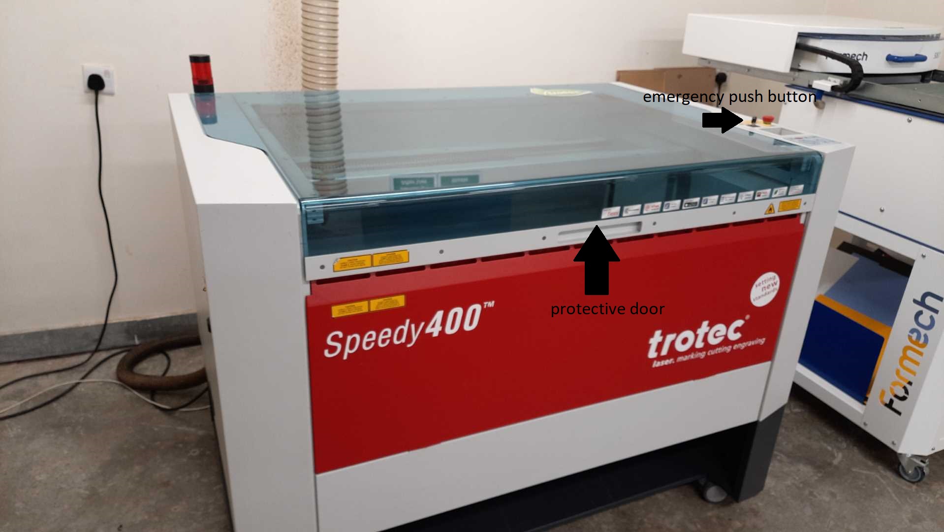
to turn the machine off, turn on the key beside the emergency push button, and wait for the machine to home its motors. then open the cover door and place the part you want to cut. using the navigation keys near the emergency push button, to place the laser hear on the part. I like to place my parts at the top left of the machine.
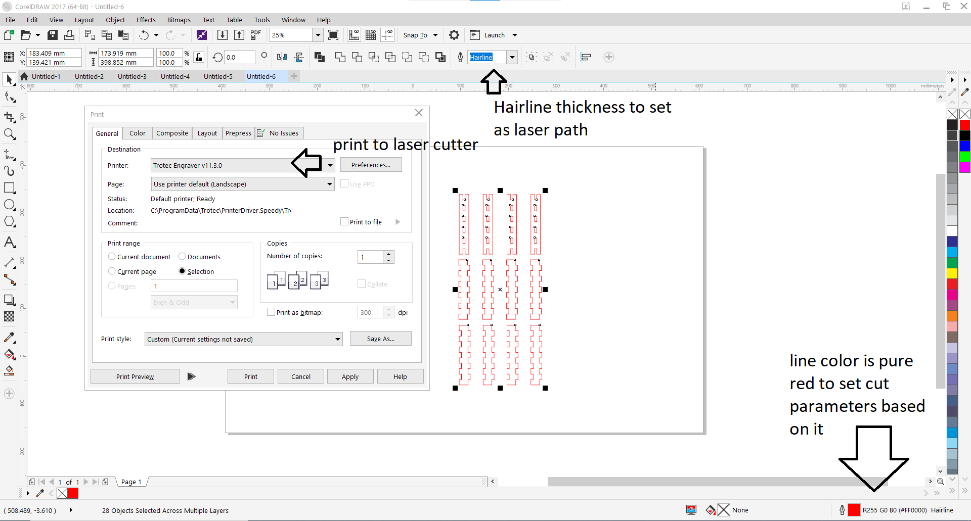
Now after the material is loaded, prepare the design. in Jobcontrol, the software that controls the laser cutter takes a vector design from a vector design software.
I will show how to export the design from CorelDraw, CorelDraw makes sure that the lines that need to be cut are as thin as possible, in CorelDRAW, it’s called Hairline thickness. then give the cut lines a pure red color #FF0000, then print and select the trotec as the printer.
JobControl software should open, from the right open the design by double-clicking. move the design to the place you need to cut.
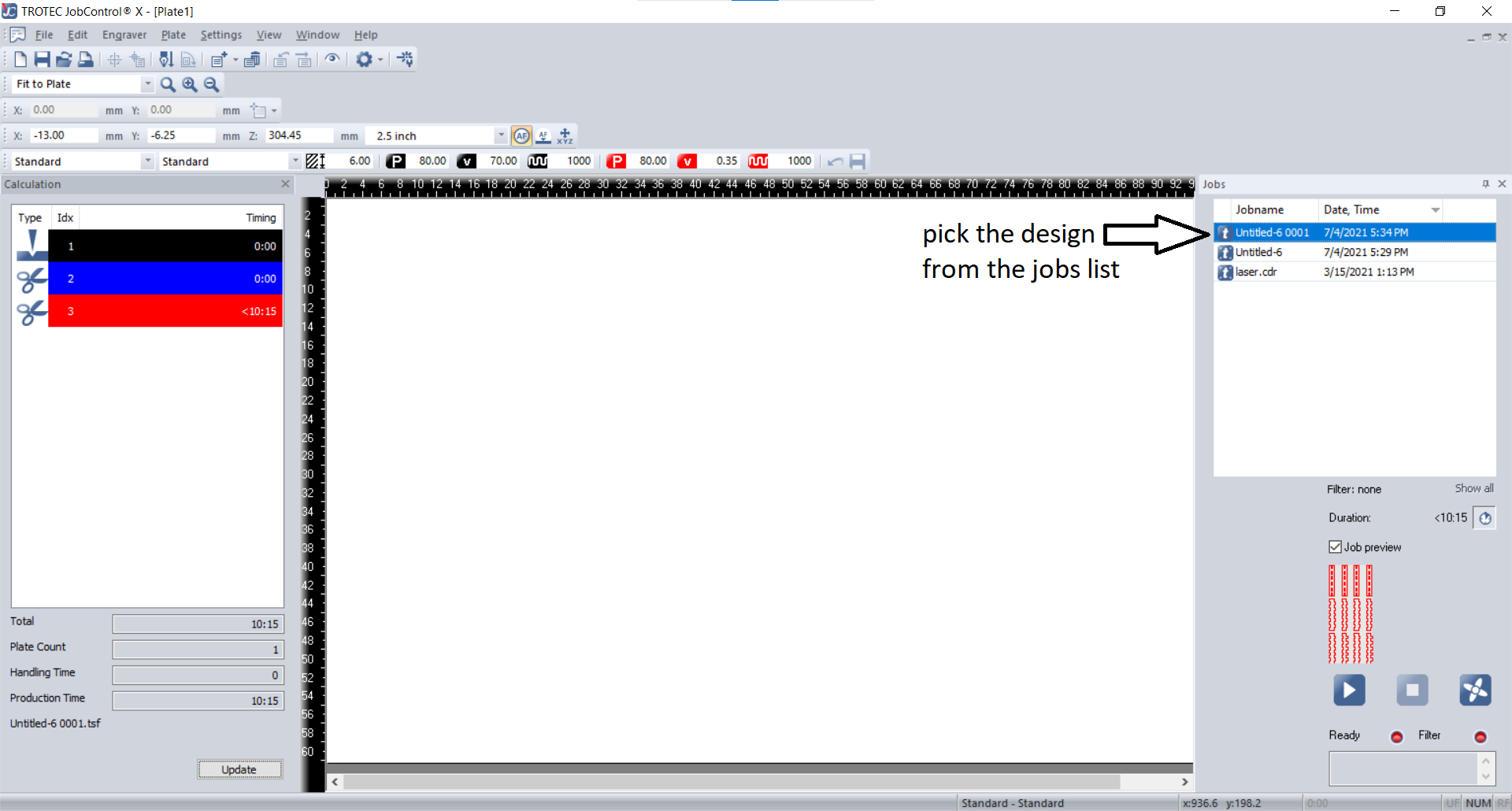
there is a button on top to should the design details, approximated time is shown on the bottom left.
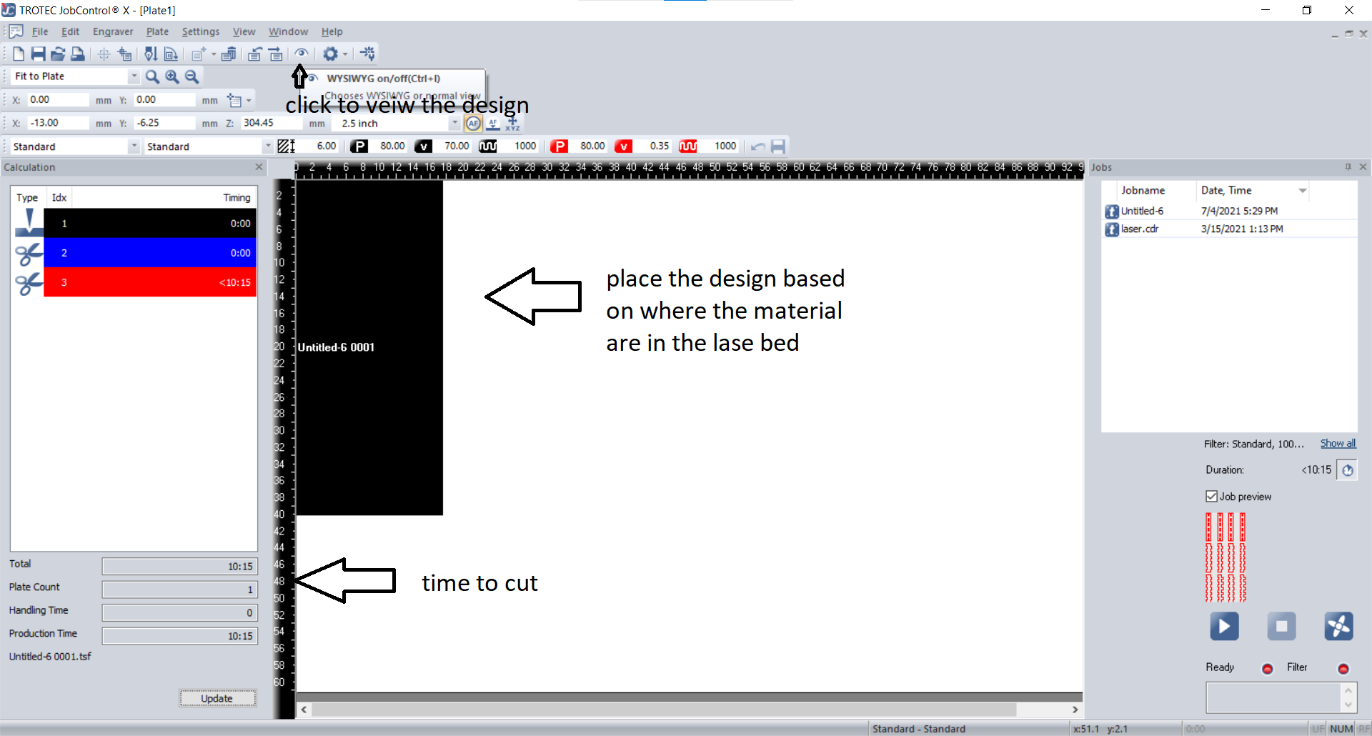
and finally, press start to run the laser job.

Testing
First I will be testing the laser cutter with three materials; 4.5mm Mdf, 5mm black acrylic, and 7.5mm plywood.
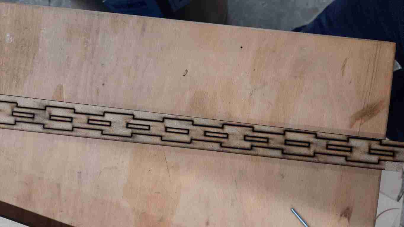
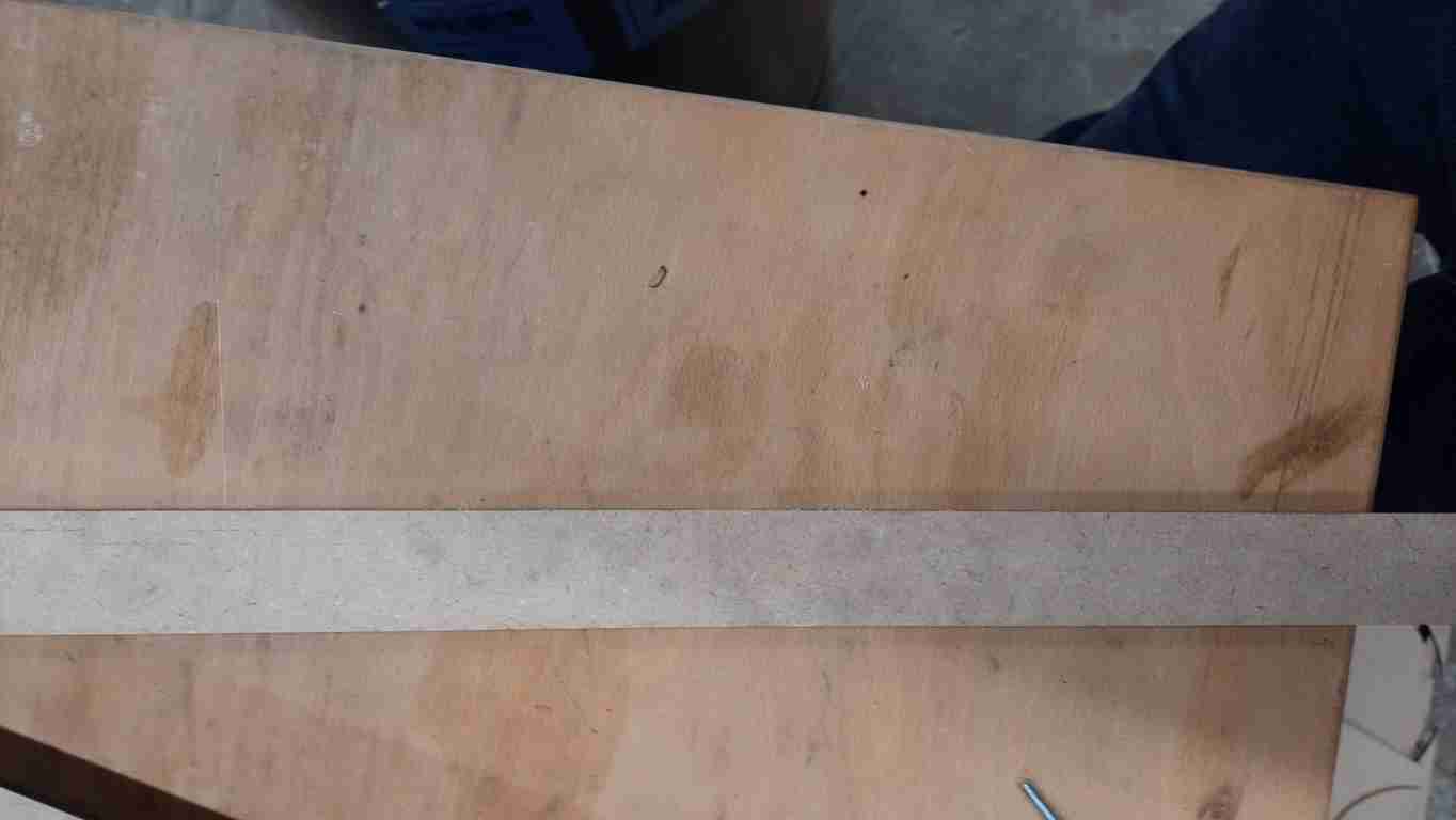
to test the cutting parameters I made a simple design that has 10 cuts side to test the cut and calculate the kerf.
cut and kerf
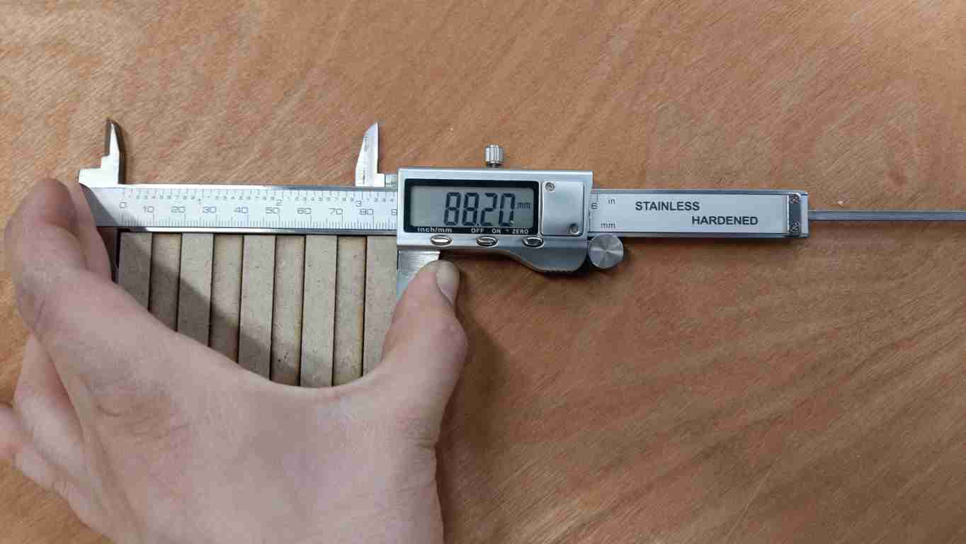
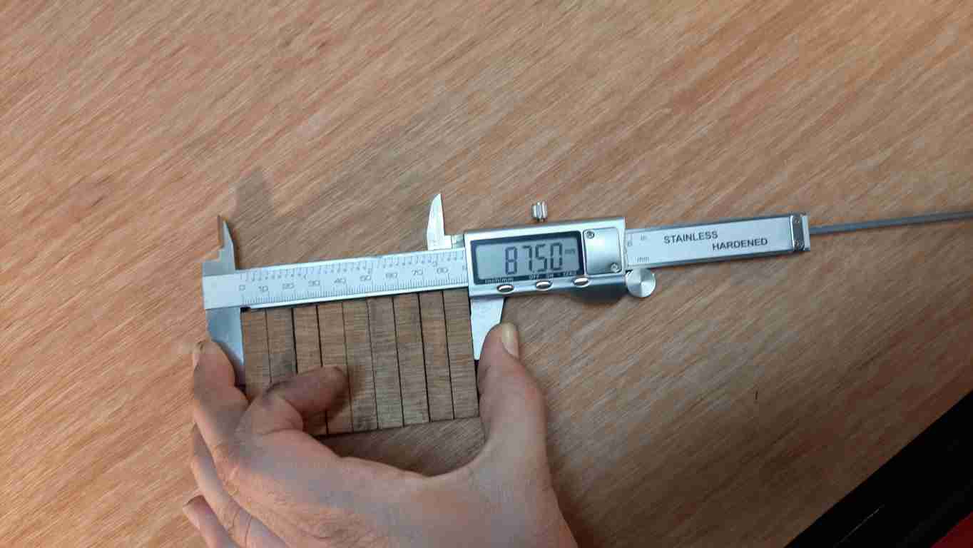
I will be starting with the 4.5mm MDF, our laser machine has an autofocus function, therefore I only needed to dial in the material thickness, and I used a constant power of 89% and only changed the cutting speed.
I started with a somehow high speed of 0.5 and kept reducing it till the laser can cut the material, measured the total length after and calculate the kerf finding the difference between the calculated width and the design one which is 90mm for all tests, then divided them by the total number of cut lines which is 10 lines for all.
here is an example using the first test for 4.5mm MDF with a cutting speed of 0.33.
(90-88.2)/90= 0.18mm
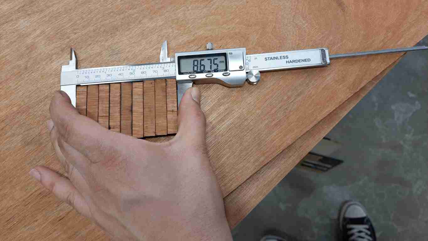
| material | thickness | speed | measurment | kerf |
|---|---|---|---|---|
| MDF | 4.5 | 0.33 | 88.2 | 0.18 |
| MDF | 4.5 | 0.2 | 87.85 | 0.215 |
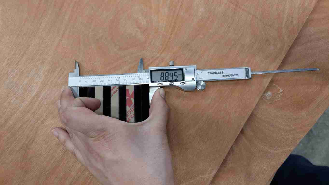
| Acrylic | 5 | 0.3 | 88.45 | 0.155 |
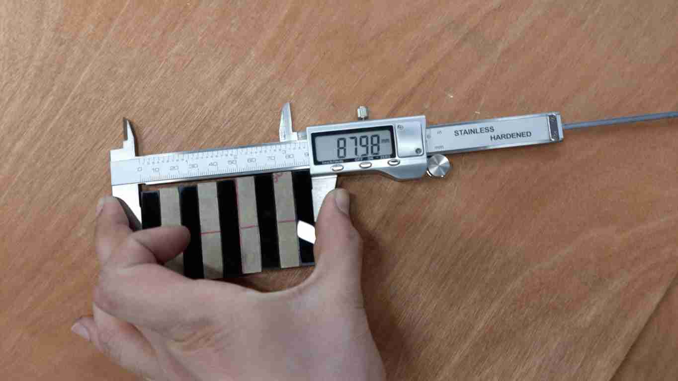
| Acrylic | 5 | 0.2 | 87.98 | 0.202 |
| Plywood | 7.5 | 0.12 | 87.5 | 0.25 |
| Plywood | 7.5 | 0.1 | 86.75 | 0.325 |
mdf kerf measurment in 0.33 speed
mdf kerf measurment in 0.2 speed

acrylic kerf measurment in 0.3 speed
acrylic kerf measurment in 0.2 speed
plywood kerf measurment in 0.12 speed
plywood kerf measurment in 0.11 speed
joints
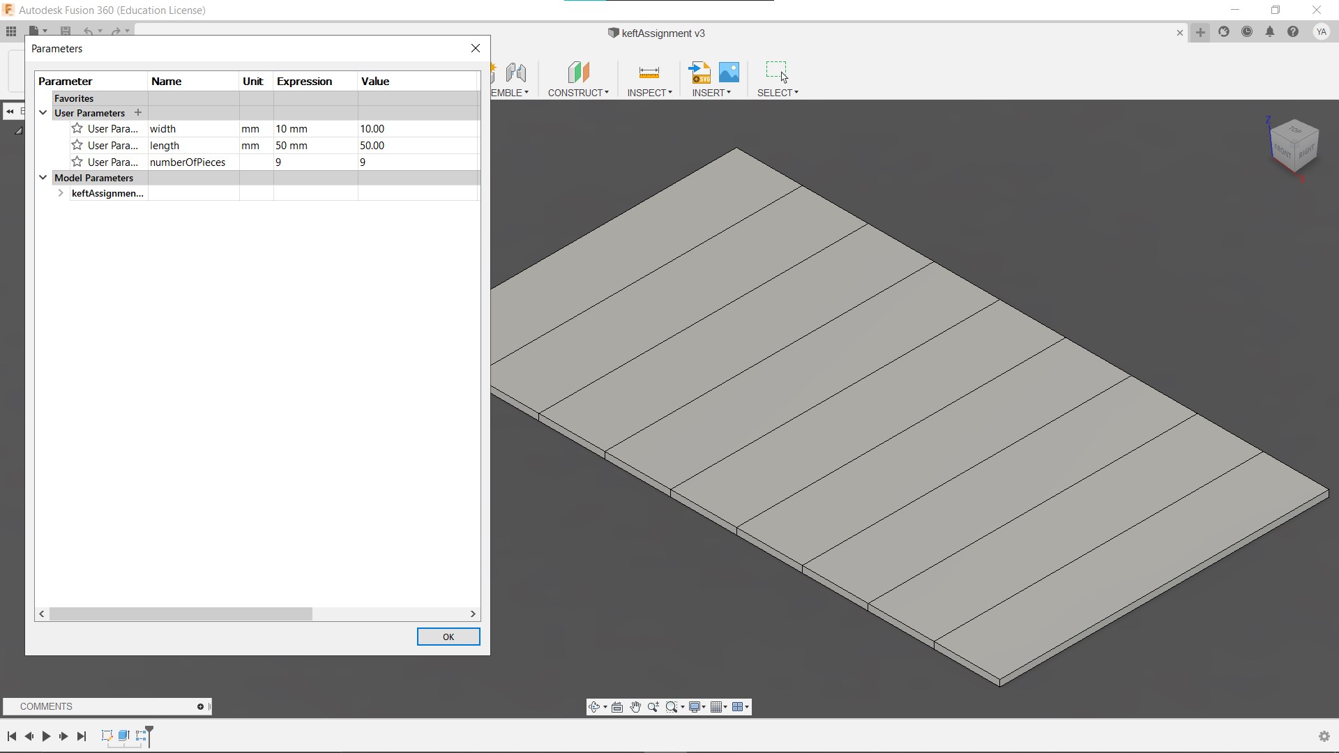
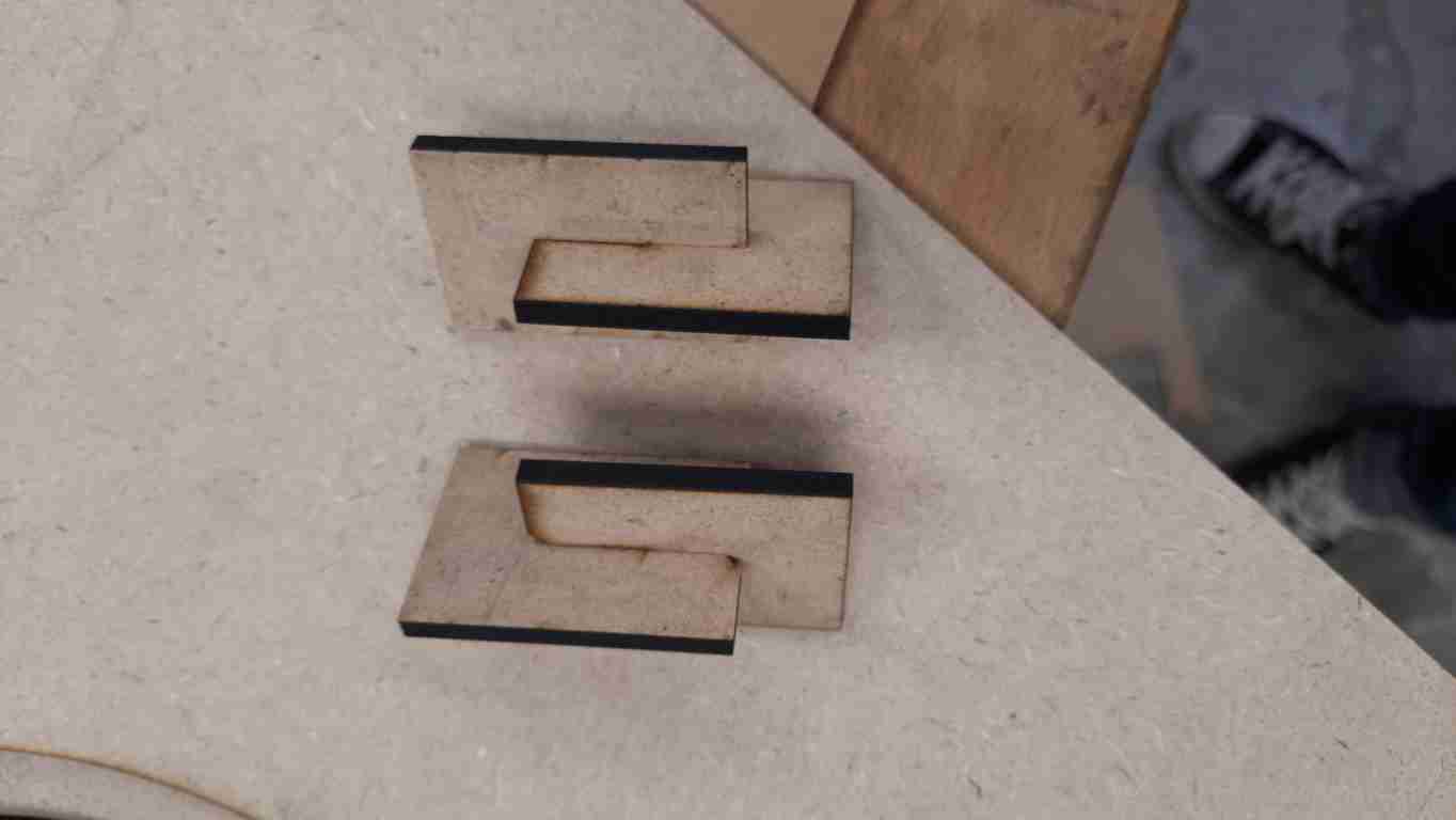
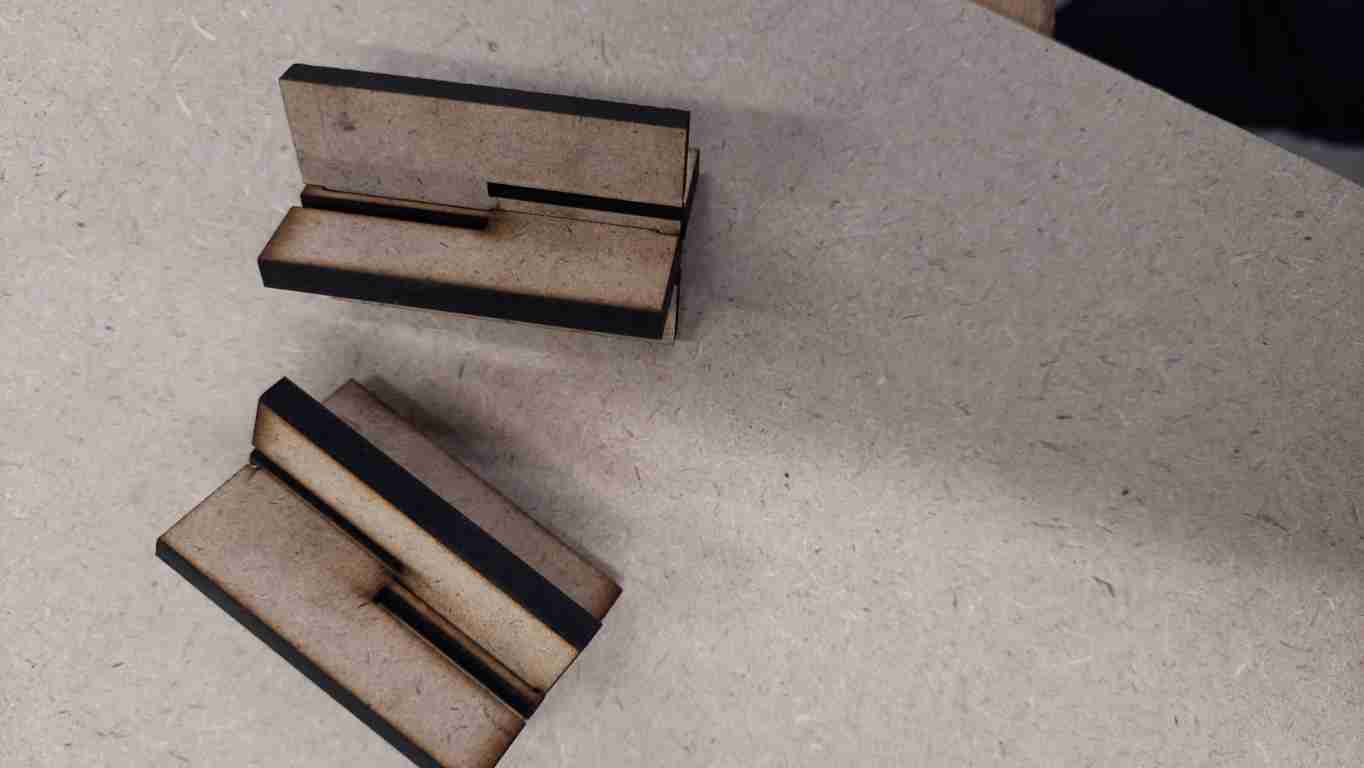
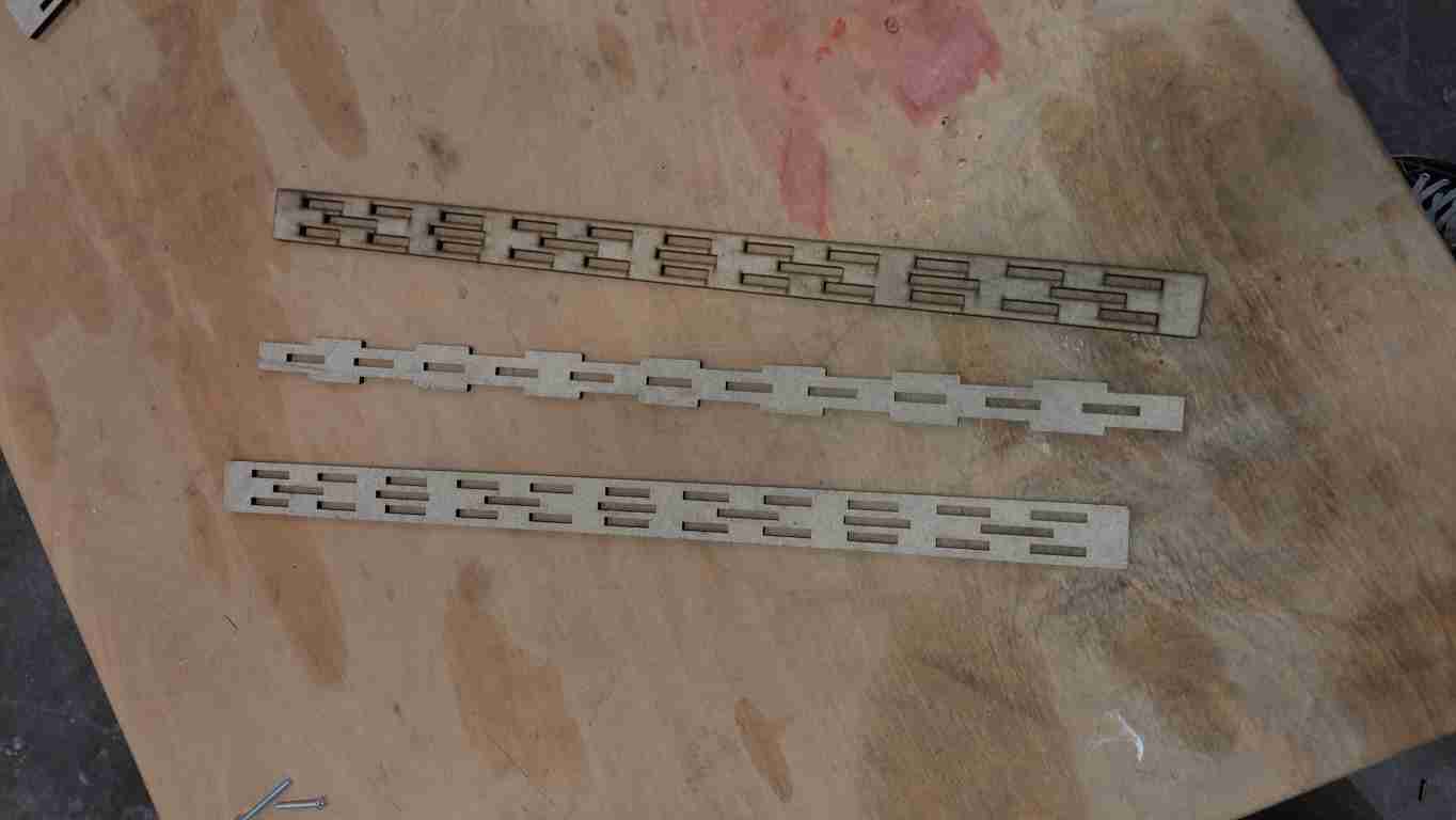
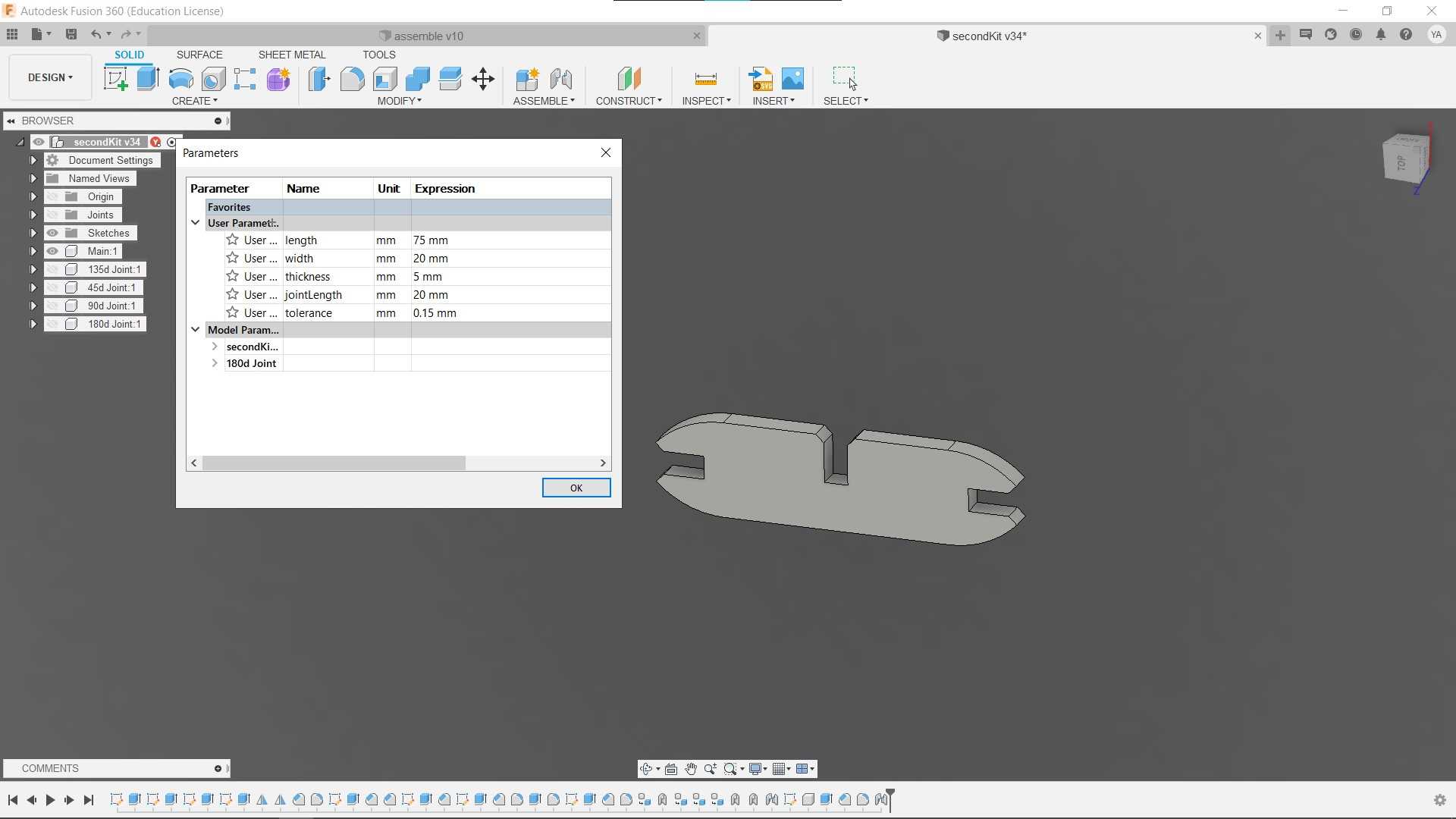
Here I wanted to test some of the joints that I am interested in, I started by making a parametric design to easily change and test the joints. I will make all the tests using 4.5mm MDF since it is the material that I want to use for this week’s project.
design

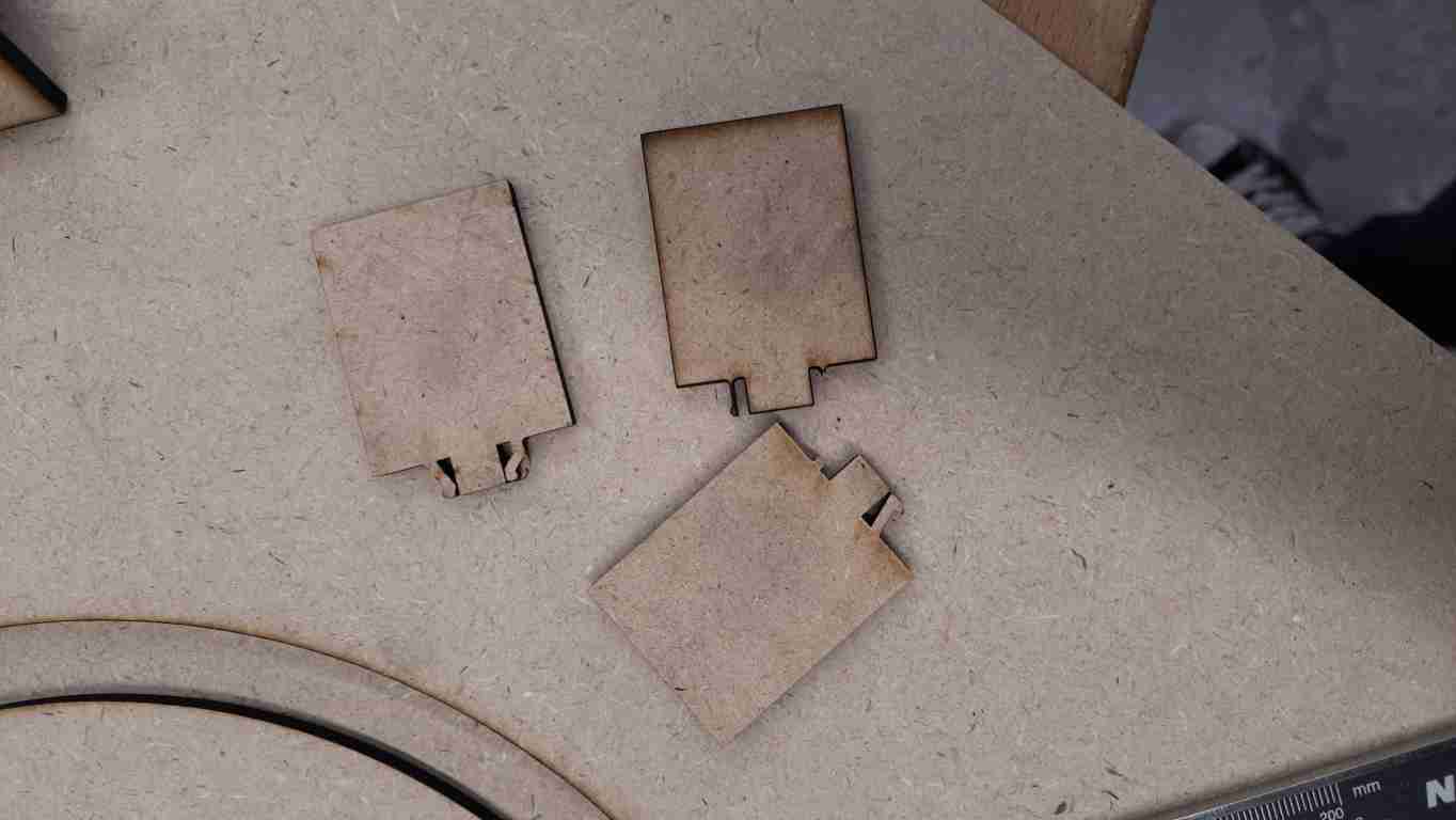
Here are the results of the snap-fit joints, adding a chamfer made assemble much easier.
snap-fit
Here are the results of the wedged joint, I like this joint, easy to design and assemble, even without making the wedge tight, the joint held up strongly.
wedged

Here are the results of the flexure joint, this joint surprised me, it is very strong, it is a bit tricky to assemble though but once it is, it holds up strongly.
flexure
Here are the results of the snap joint, no matter what parameters I use, I could not get this joint to work, I guess the material is too thin and only 4.5mm for the flexure part is not enough to make it flexible enough.
snap
design
first design
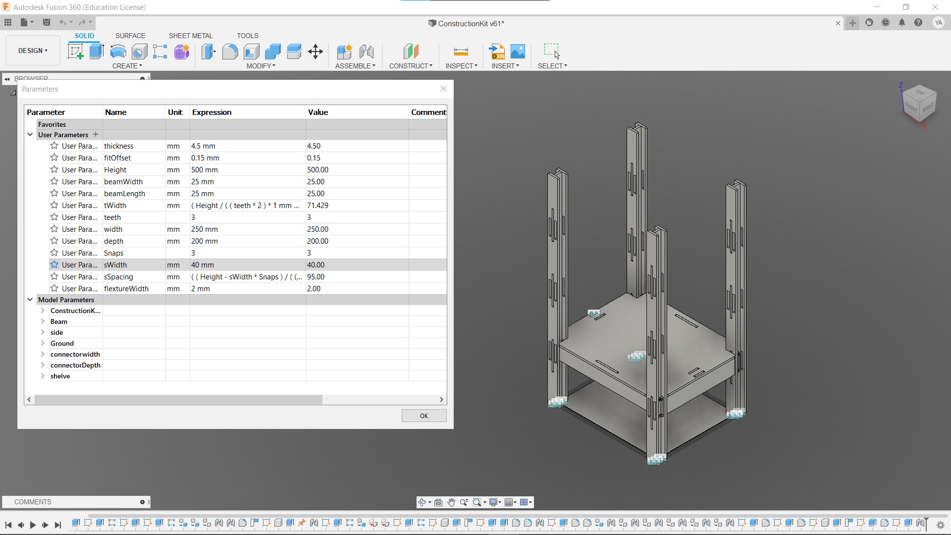
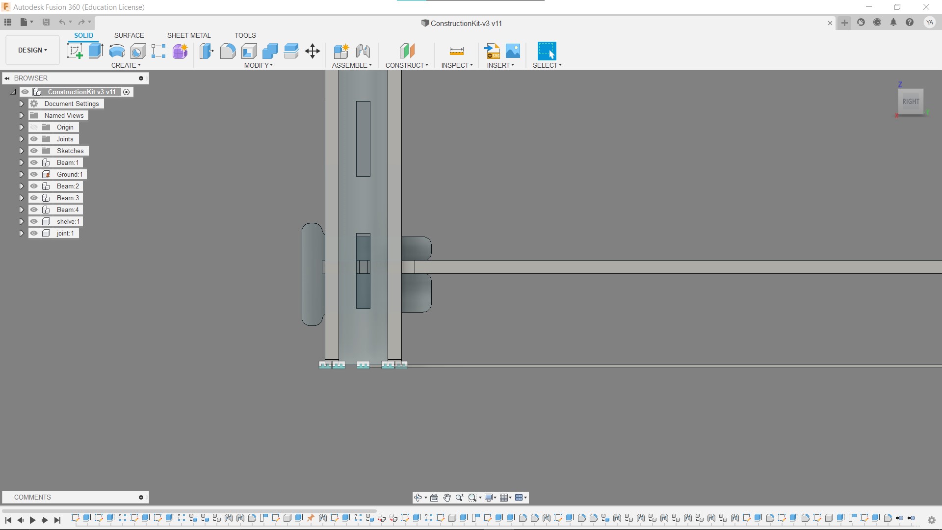
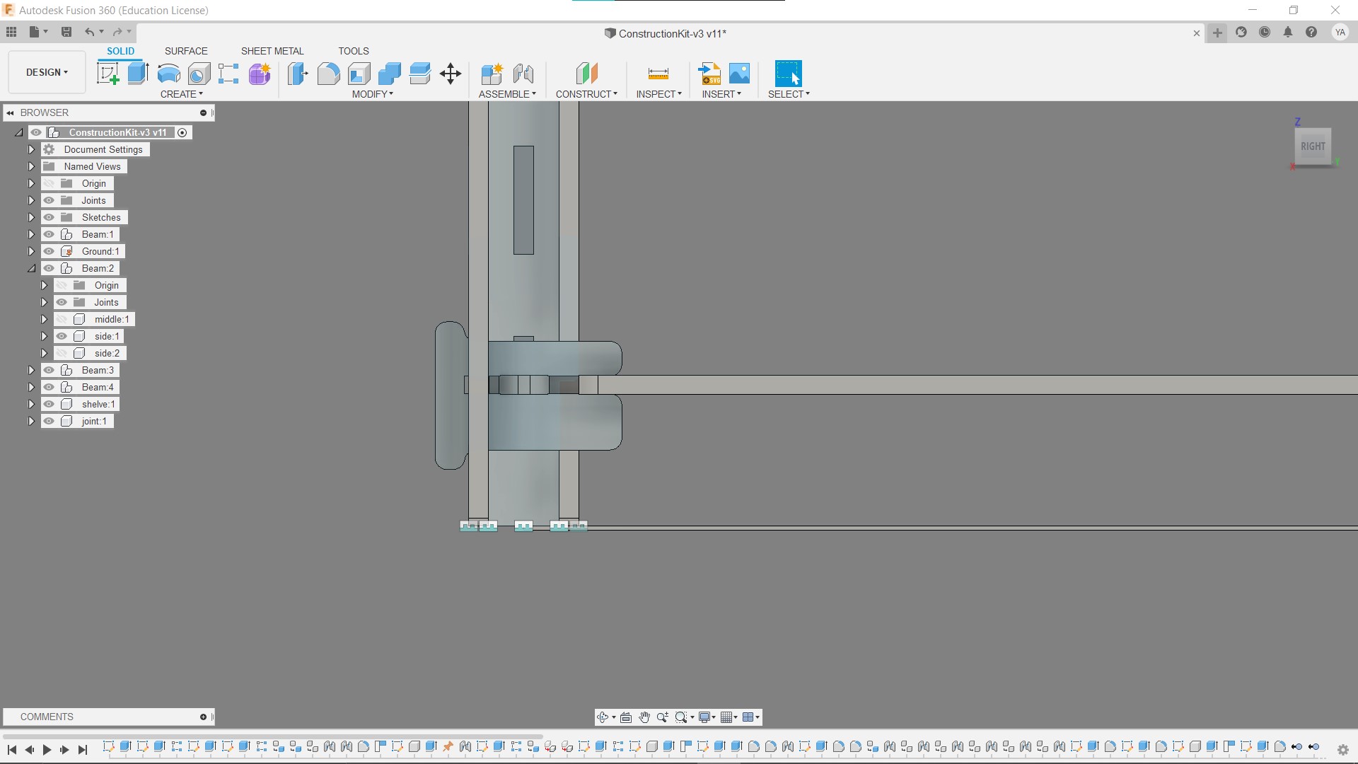
the main idea of this design is to use an “I” shape beam which will give the material strength and less likely to bend over high lengths.
I set the parameters as I designed, making sure that every part of the design is linked to them from the number of finger joints that link the beam to the fir offset of the snap-fit joints of the beam.
parameteres

parameters test, demonstrating how the design reacts with changing most of the parameters.
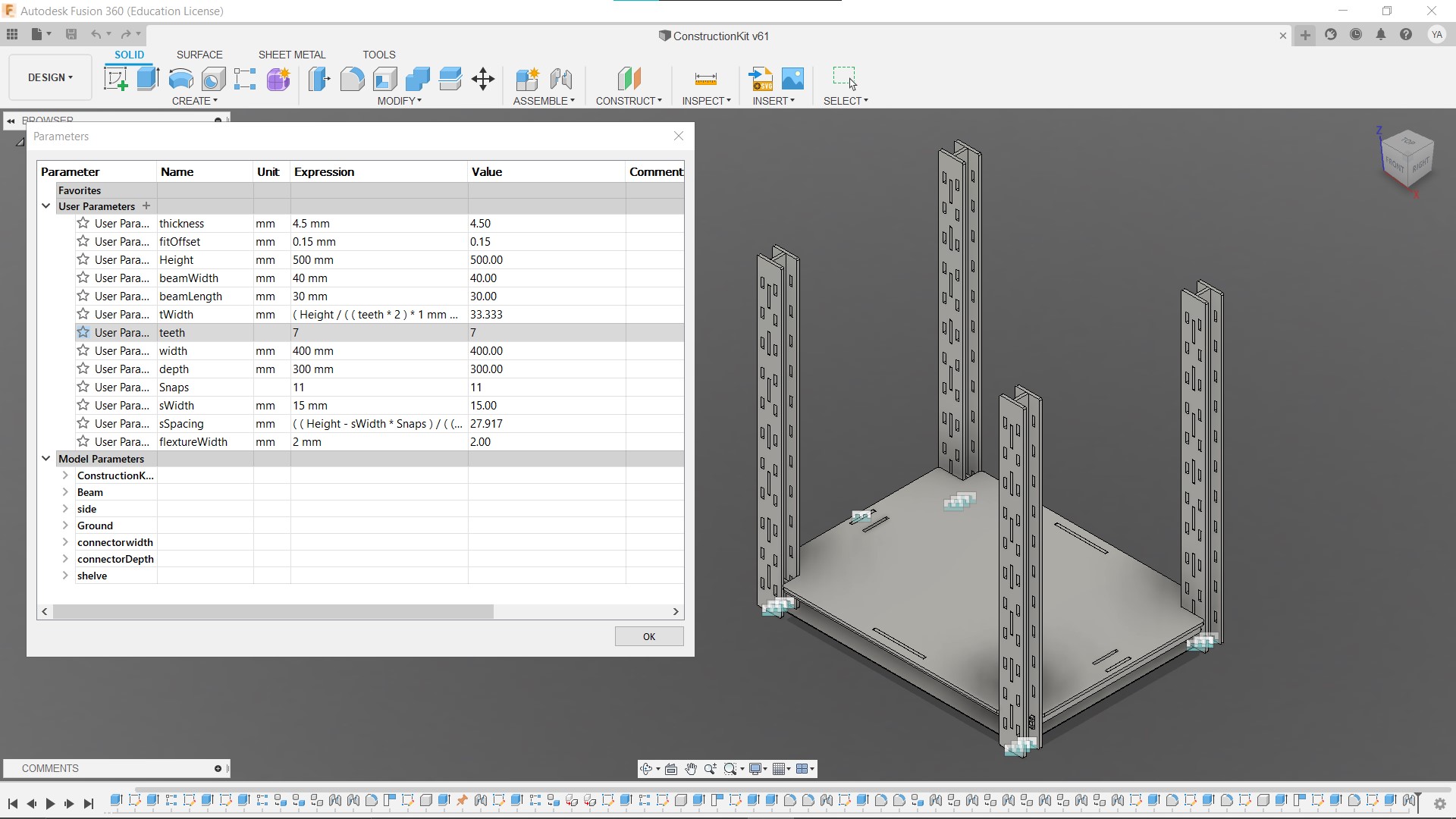
parameters test
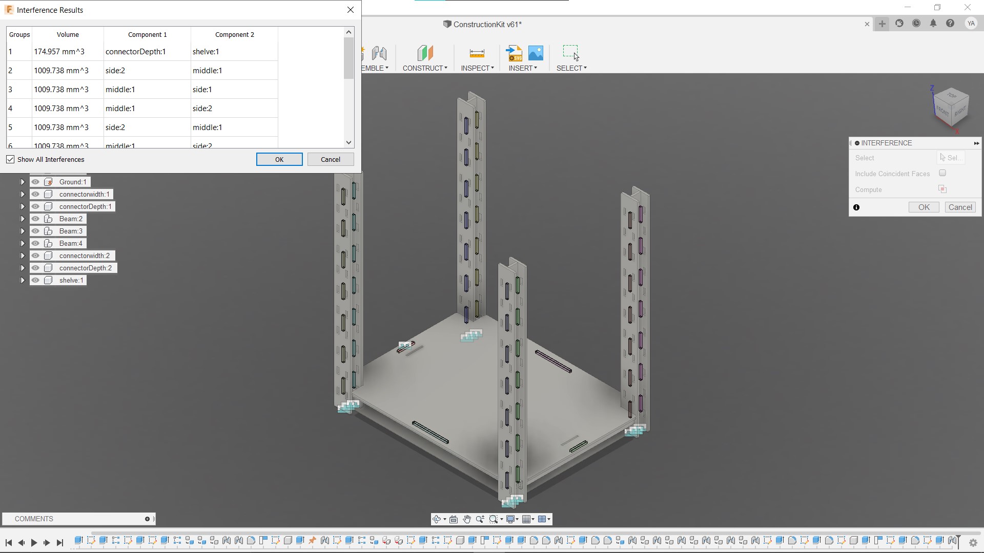
snapfit interference test
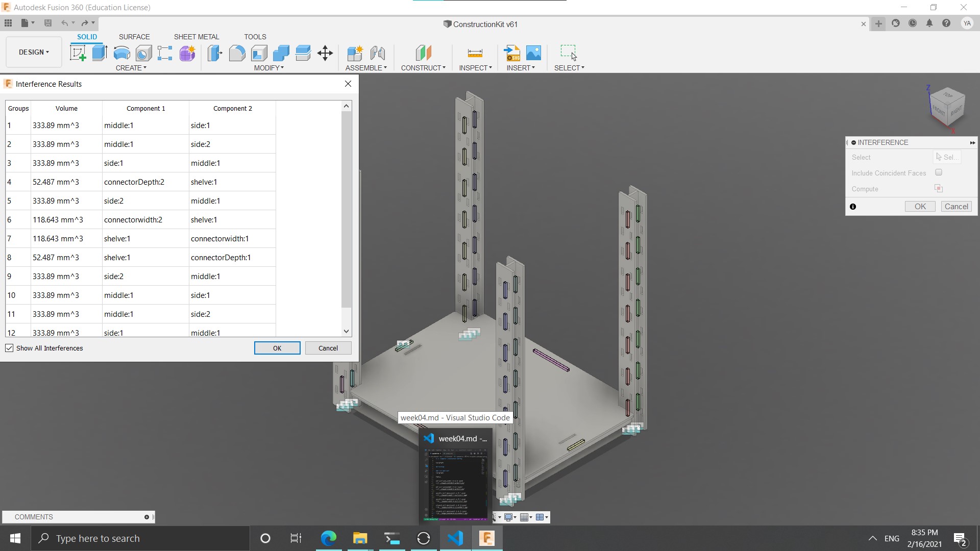
snapfit interference test
I wanted to use stretches to link the beams to each other and holds the shelve with snap-fit fingers, but since I could not make this joint work with this material, I had to redesign and use another joint.
snap joint


second design
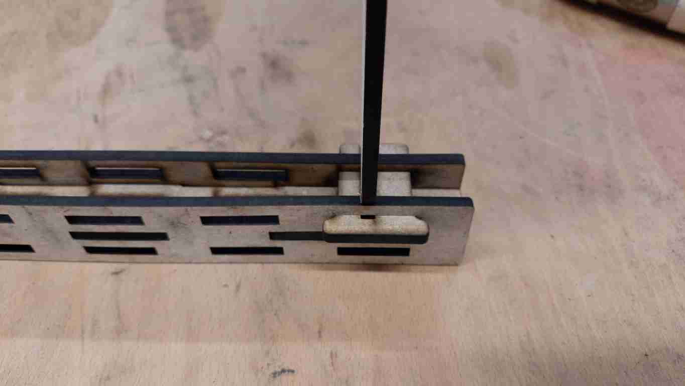
In the second design, I use a cross joint that goes through the beam and snaps into the shelve, it worked very well, after some hammering in the shelves turned to be very sturdy.
wedged joint
Live veiw
cutting and assembly
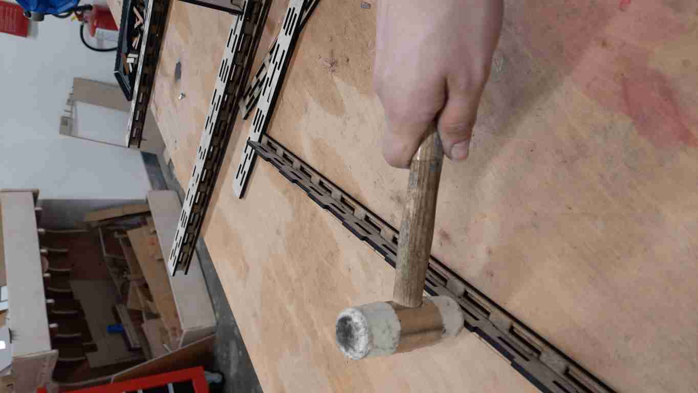
Here is the process of assembling the structure after cutting it. I started by hammering in the beams to form their final shape, I added a small chamfer to make the assembly easier.
beam parts
beam hammer in
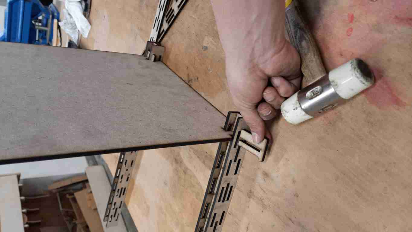
Here I am showing the joint assembly.
joint
joint hammer in
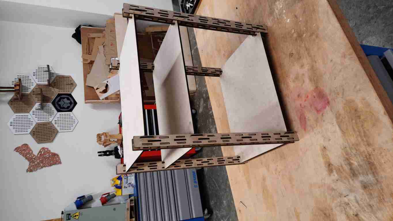
The final result
laser cutter issues
When I cut the project some issues occurred from a not very clean-cut, to did not cut at all, although I did test the cutting parameters first, I found that because the boards that I used were bent, the focus was off at some parts, I overcame this issues by cutting each part alone making sure to adjust the material thickness according to the hight of the board at the place that I wanted to cut in.
not fully cut
did not cut at all
third design
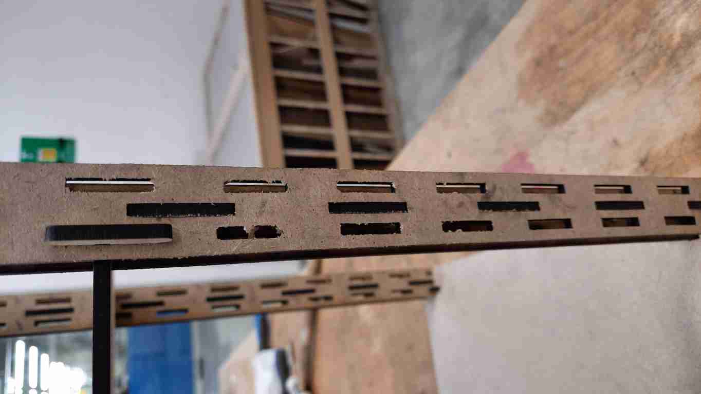
this design is for a more generic construction kit, the goal is to make a basic building block to be connected from multiple sides, and joins to connect these blocks. I made the joints with multiple angles, 180, 90, 45, and 135 for more build options.
the design is parametric, I can change the kirf fit, the thickness, the length of the parts just like the previous design.
Here is the main building block.
A 90 degree joint
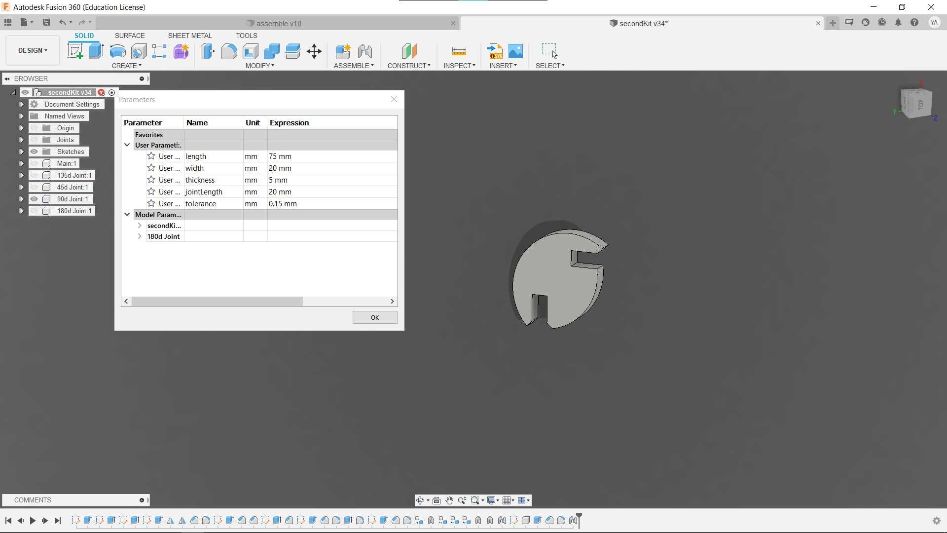
A 180 degree joint
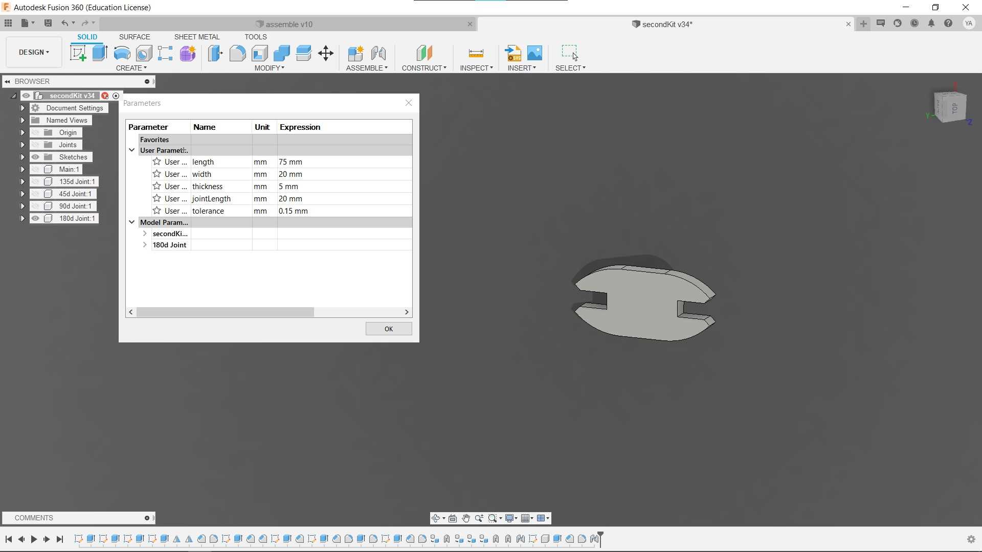
A 45 degree joint
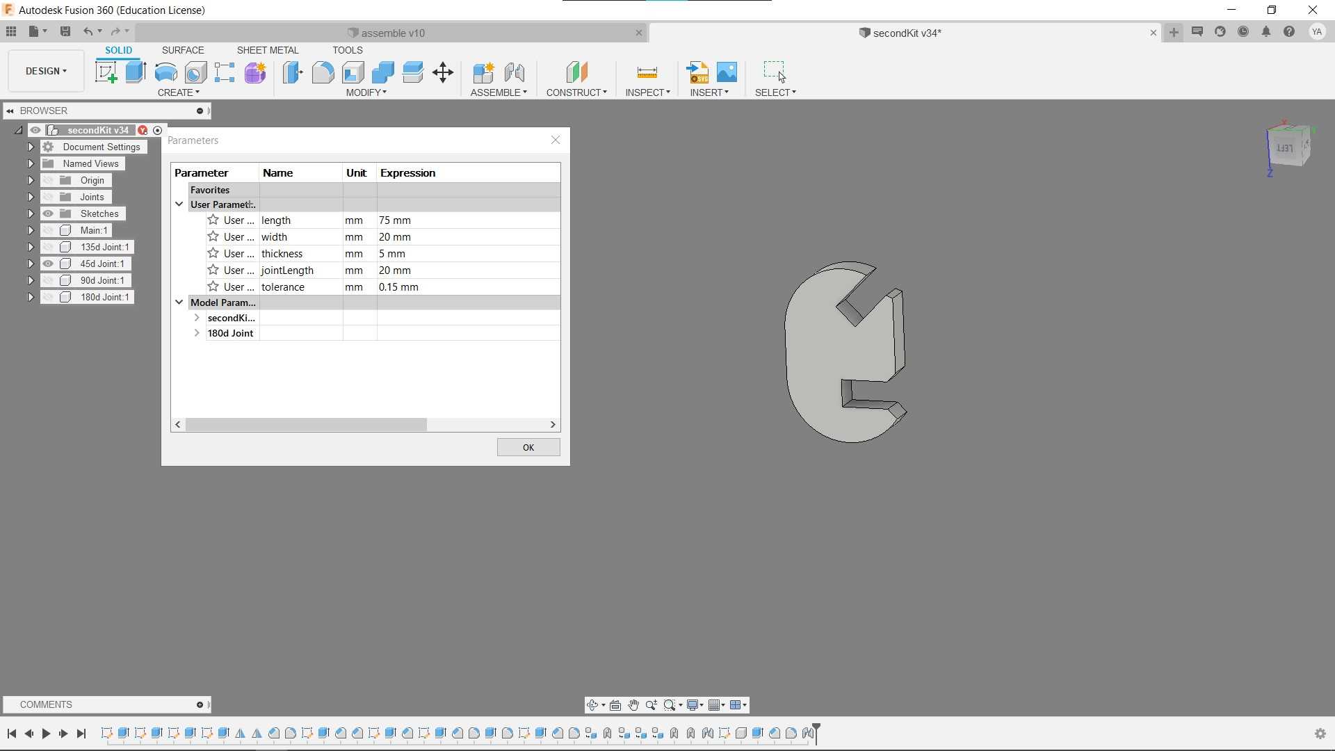
A 135 degree joint

here is a simple construction inside fusion 360
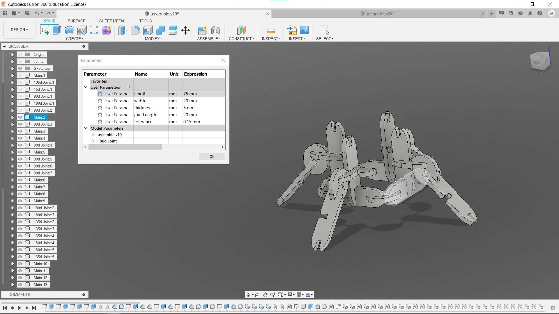
changing the length of the main part
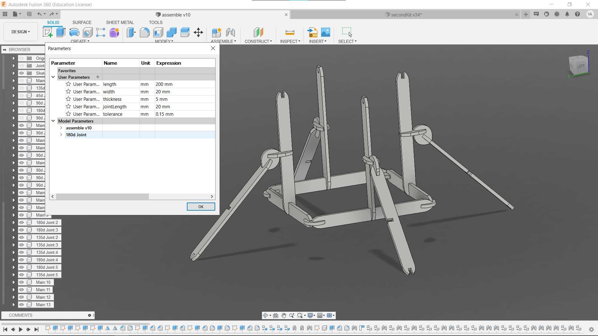
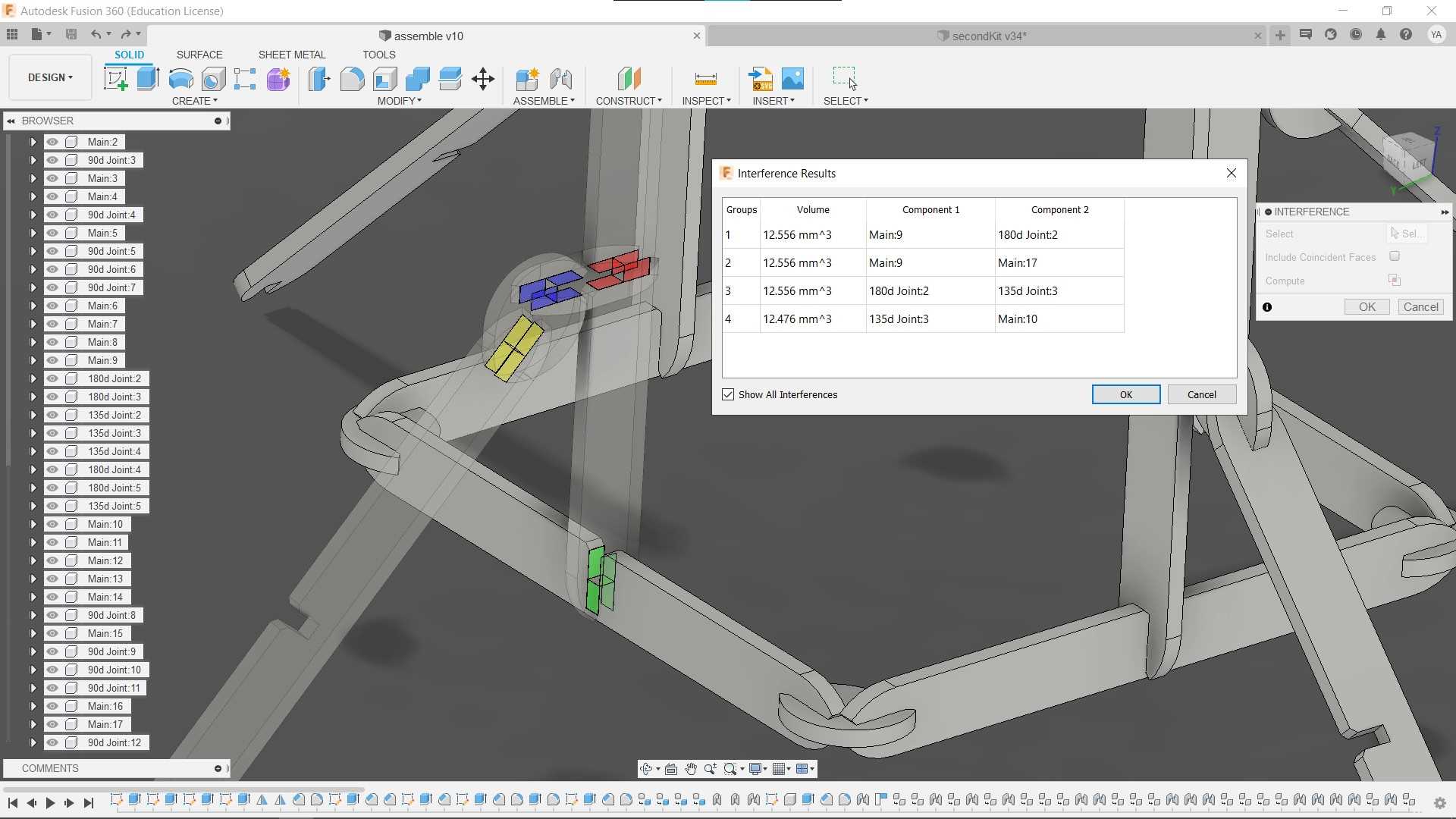
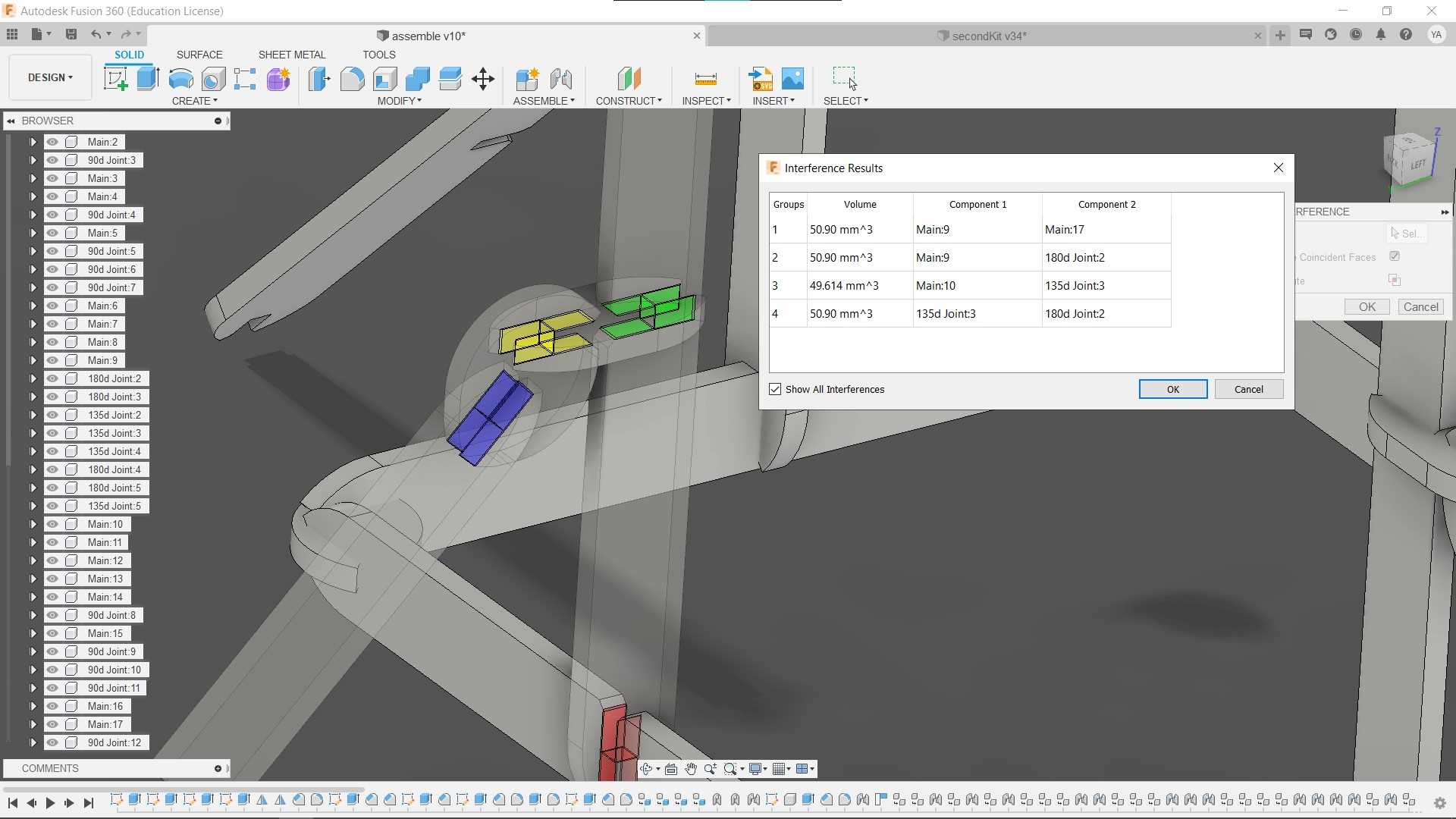
and here are intersection analysis to should the keft compensation
vinal cutter
design
In the vinal cutting part I wanted to try cutting a PCC using copper tape, I started with a simple PCB design from Autodesk eagle, converted it to a curve design, then tracing the cutting outline.
cutting
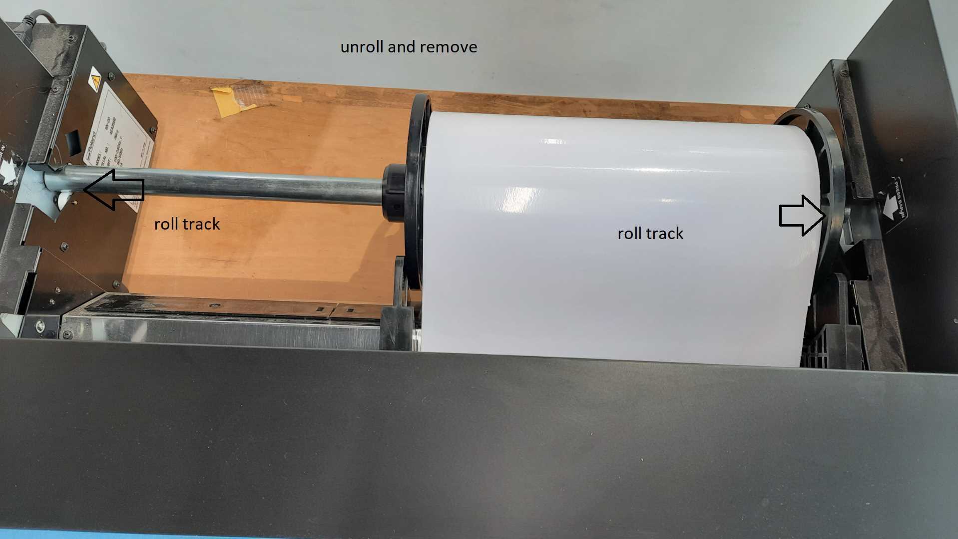
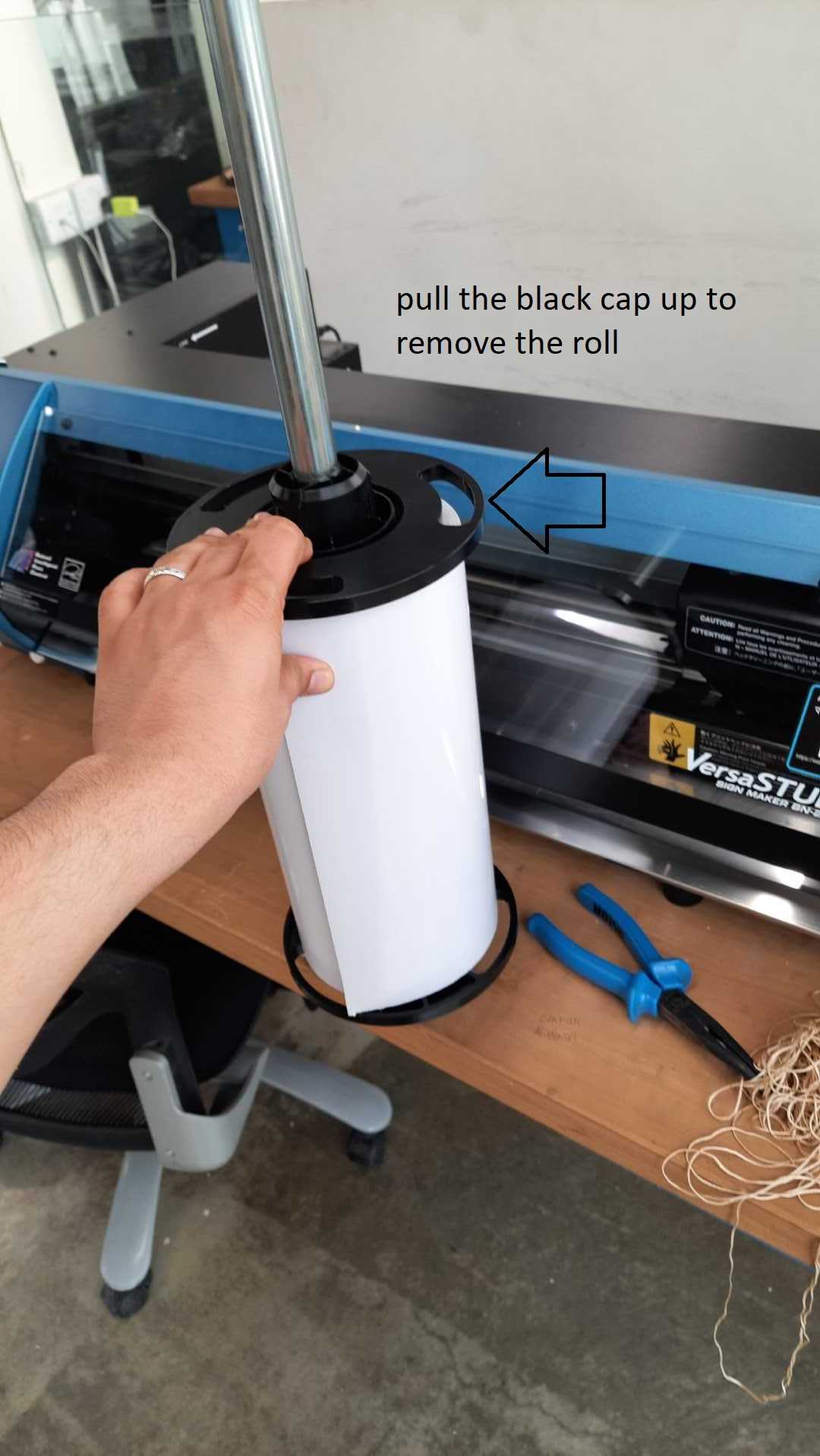
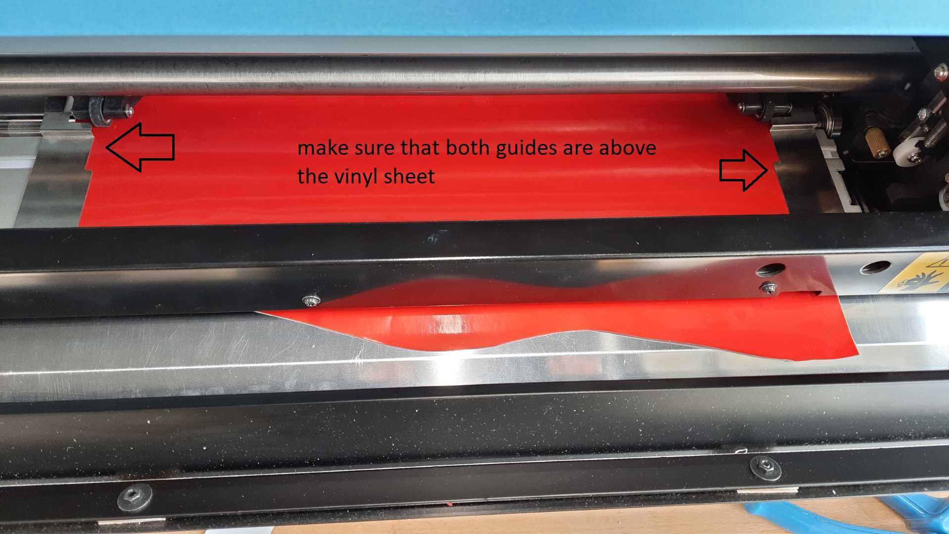
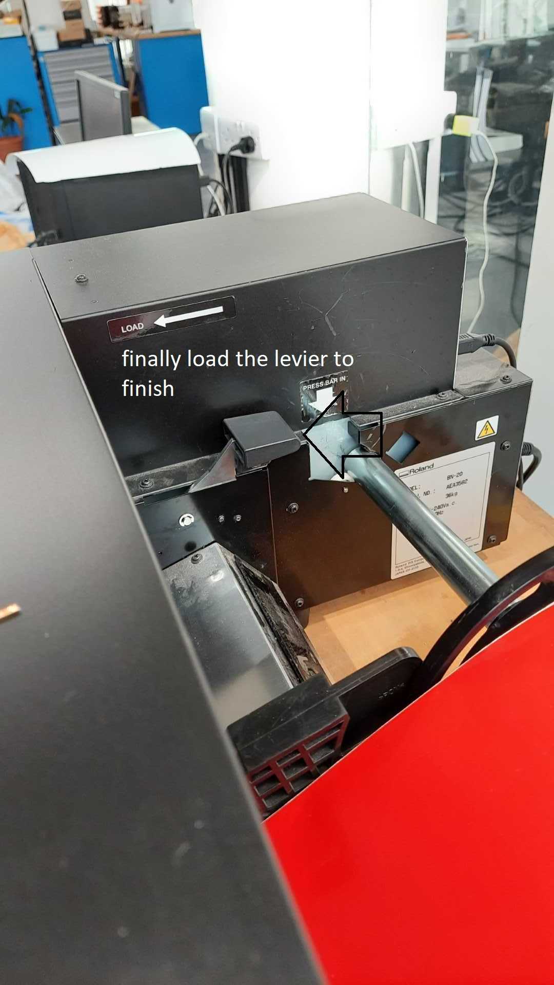
First install the vinyl roll you want to cut by following the steps in the following images.

after installing the vinyl roll, open theversaworks software, making sure that the printer is ready to print
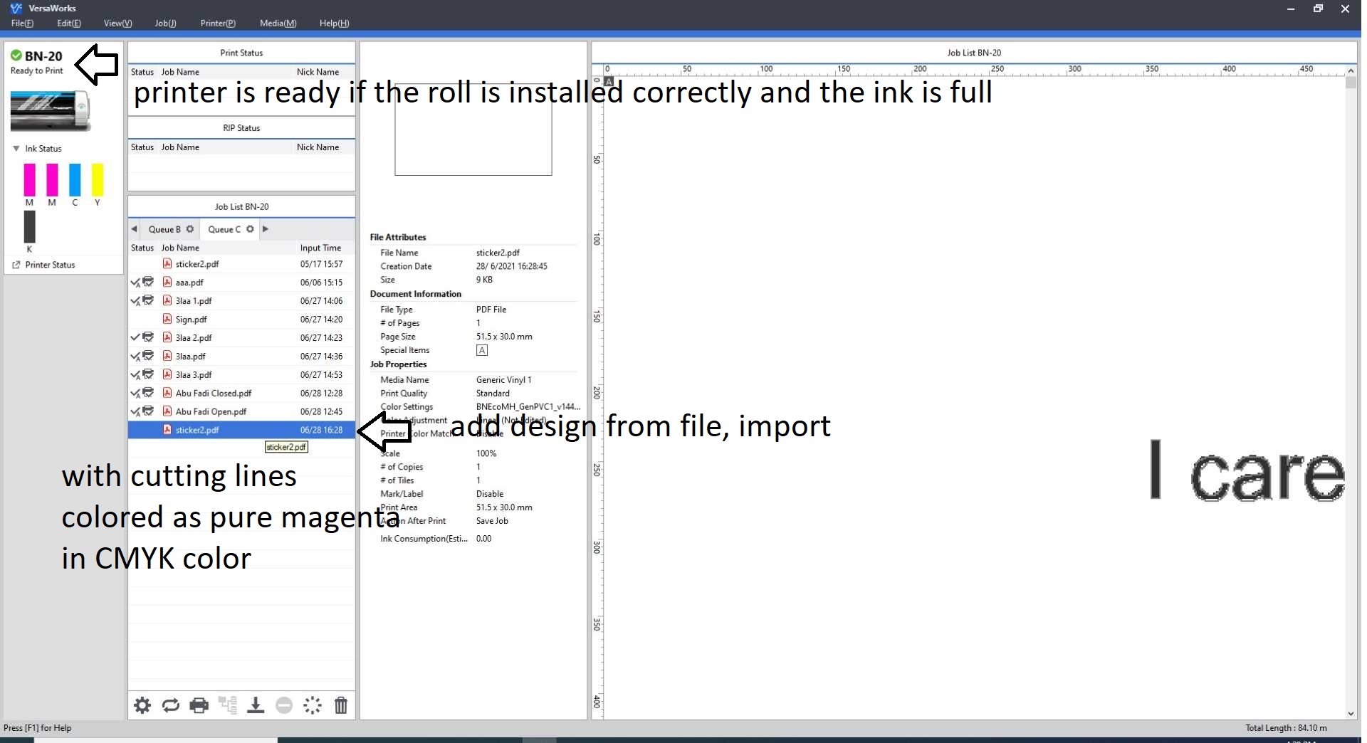
I started with testing the cutter with vinal material, made a sticker for my laptop with the PCB desige, following versaworks manual to learn about the interface and simple operation.
import the design to versaworks software
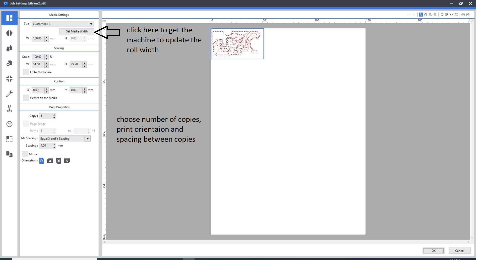
cutting parameteters
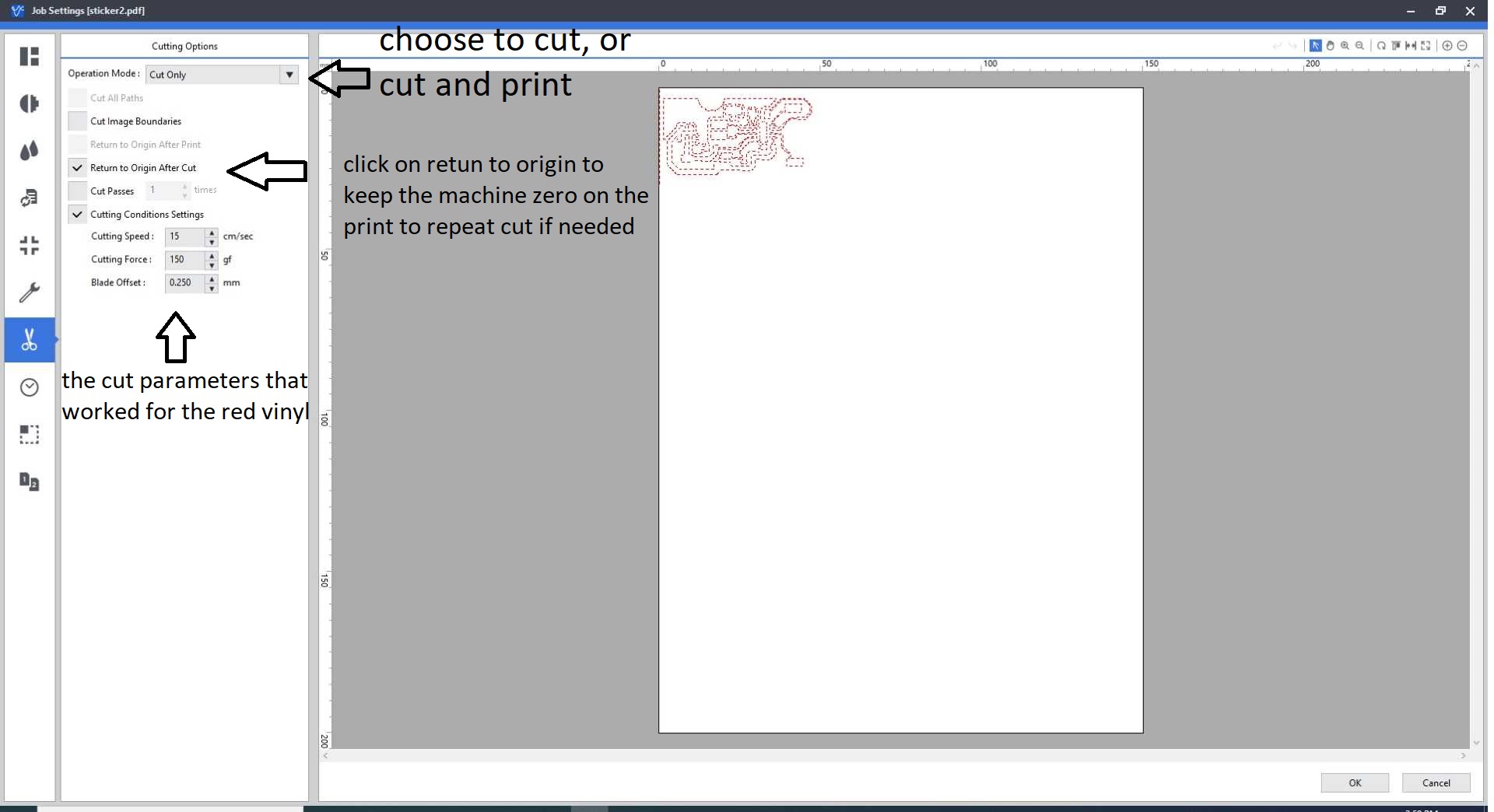
test cut on vinal

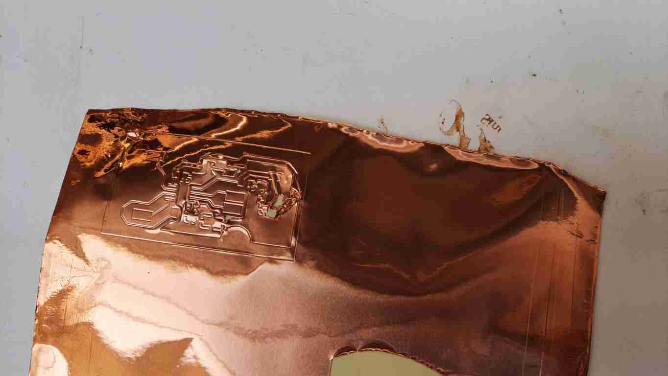
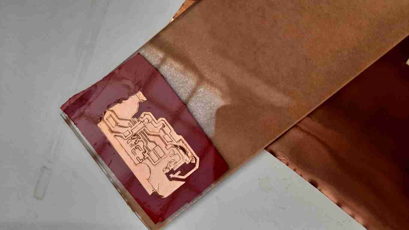
after I learned how to cut and tape the design I moved to try to cut it using copper to be a usable PCB, no matter what parameters I use nothing worked.
failed copper

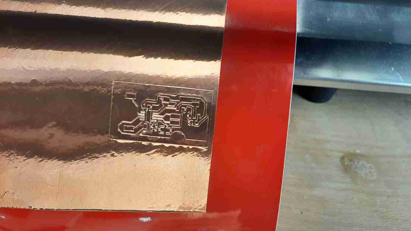
Then my instructor told me to try and tape the copper on top of a vinal material to add strength to it, and it worked, but sadly I wasn’t able to successfully remove the excess parts without ruining the copper. since I was out of time I gave up on it, maybe I’ll get back to it in another week.
tape copper to vinal
cut sucsess

fail to remove excess
Design Files
click here