5. Electronics production
This week is about Electronics production, I will be making a programmer PCB using the Roland srm-20 desktop milling CNC.
cutting parametars
The first part of the assignment is to try PCB cnc milling on a test design to figure out the design rules to be used in the electronics design week.
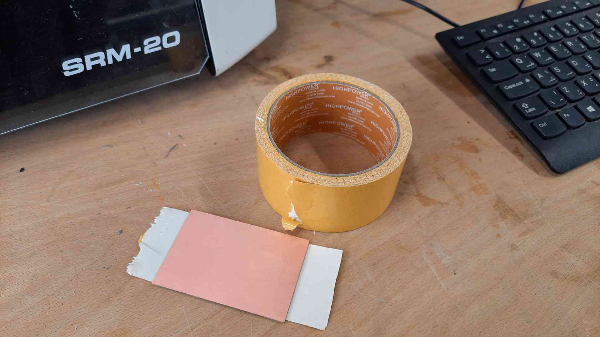
- First I will mount the stock to the CNC bed using double-faced tape.
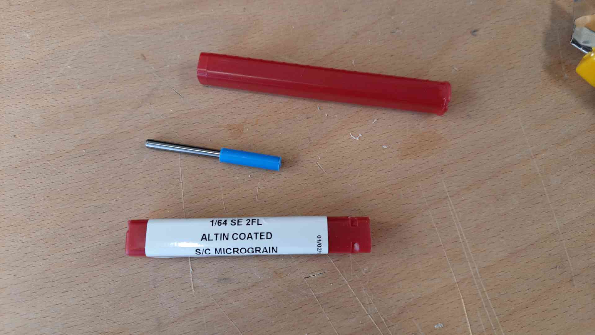
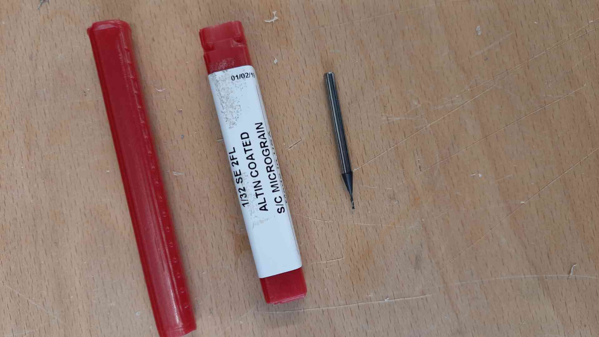
- Here is a photo of the endmill that will be used for milling the traces.
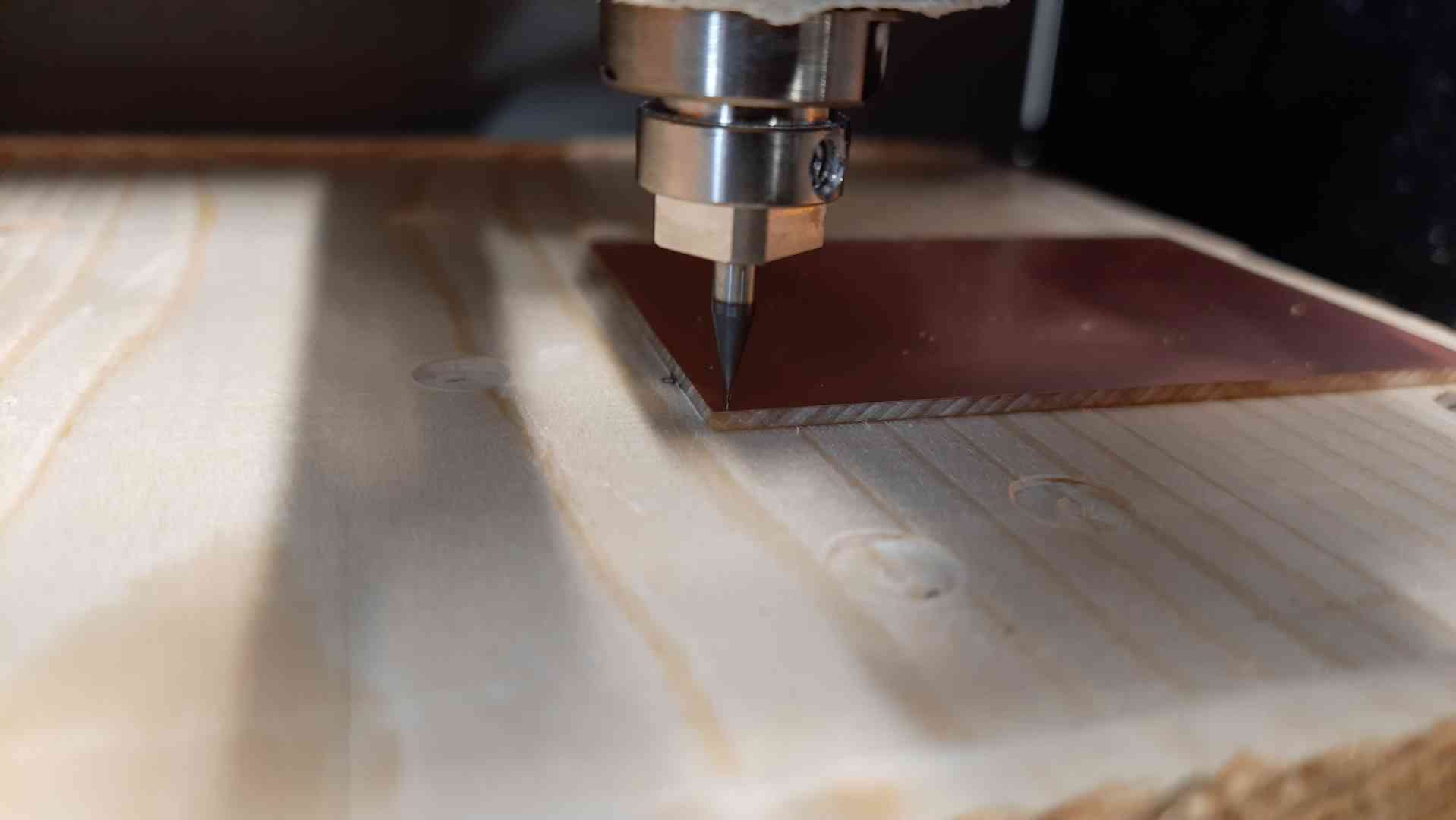
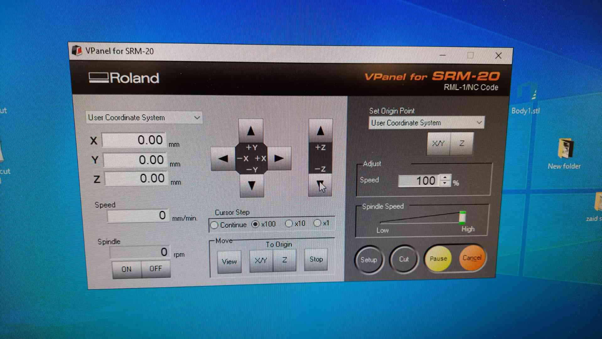
- Mount the stock to the bed and set the zero, taking care to lower the endmill by hand when setting the Z zero.
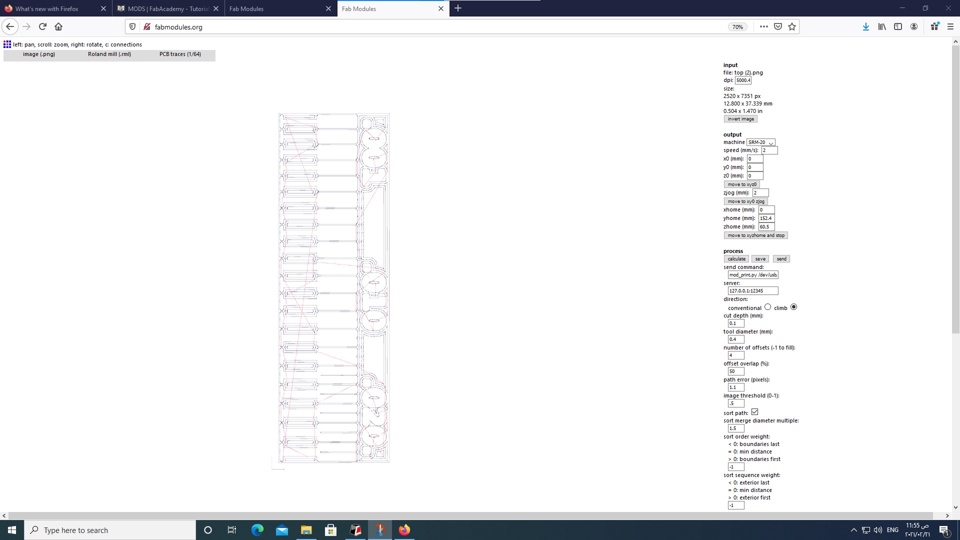
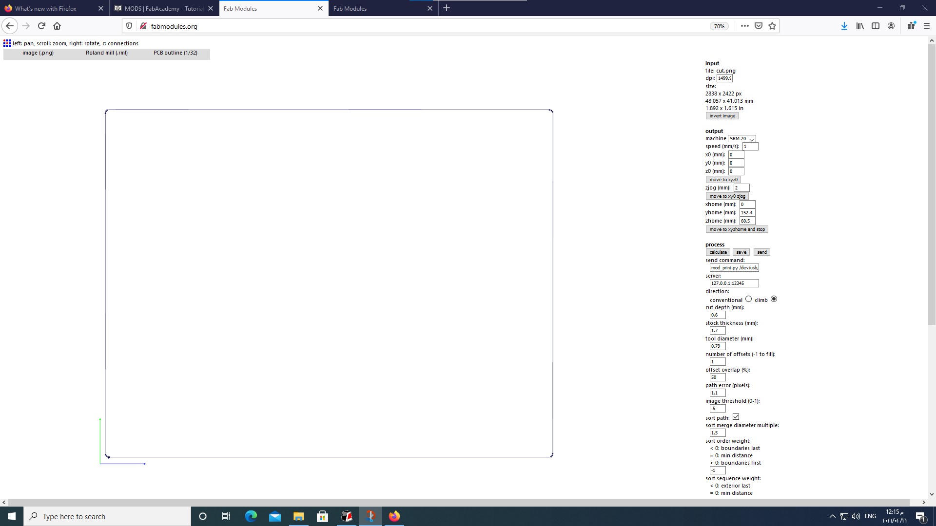
- Using FabModules to prepare the CAM, Here are the parameters I used.
- Once the machine had started milling for a moment, I prefer to pause it and check whether it is milling into the copper or not, if there is no white dust presents the milling is not going through the copper layer.

- To fix the issue, I canceled the job, move the endmill away from the PCB stock to not harm the endmill when I lower it. I set the Z zero to be 0.05mm below the one it milled on earlier, and then relaunch the CAM file.
here are the results after lowering the Z zero.

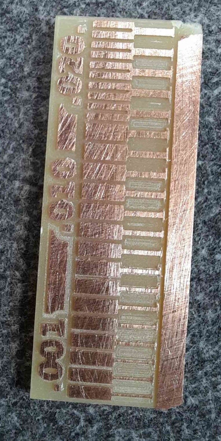
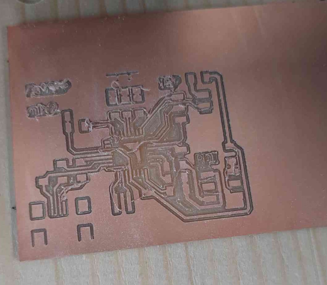
- The result after the machine had finished milling, the endmill is a bit old and it shows how rough its cutting is.

- To fix it, I lightly sanded the whole board with a 300 grid sandpaper, taking care not to put too much pressure to not harm any small traces.
PCB Manufacturing
The second part of this weeks assignment is to manufacture one of the PCBs given, I have made the tinyISP programmers in the past and I use them all time, I want to try and make another one, I will be making the FabPDI PCB by Zaerc, becuase I mostly work with Atmel AVR and I have the components for it.
Old PCB
- Here is a photo of the ATtint44 tinyISP programmer, it needs 1/64 milling bit for the traces, it was one of the first PCBs I had made in FABLAB Irbid, I removed all the nontraces copper in this PCB and it took ages to finish.
- Here is a photo of the ATtint45 tinyISP programmer, I redesign this PCB to be milled using 1/32 milling bit for faster manufacturing, we use this PCB as an entry assignment for people that want to learn to make PCBs here in FABLAB Irbid.
FabPDI
To this week’s PCB, the design that is included in the FabPDI project has an 8Mhz crystal, and I only have an 8Mhz resonator in stock, therefore I recreated the same design in Autodesk Eagle and only replaced the crystal with the resonator I have in stoke.
My redesign
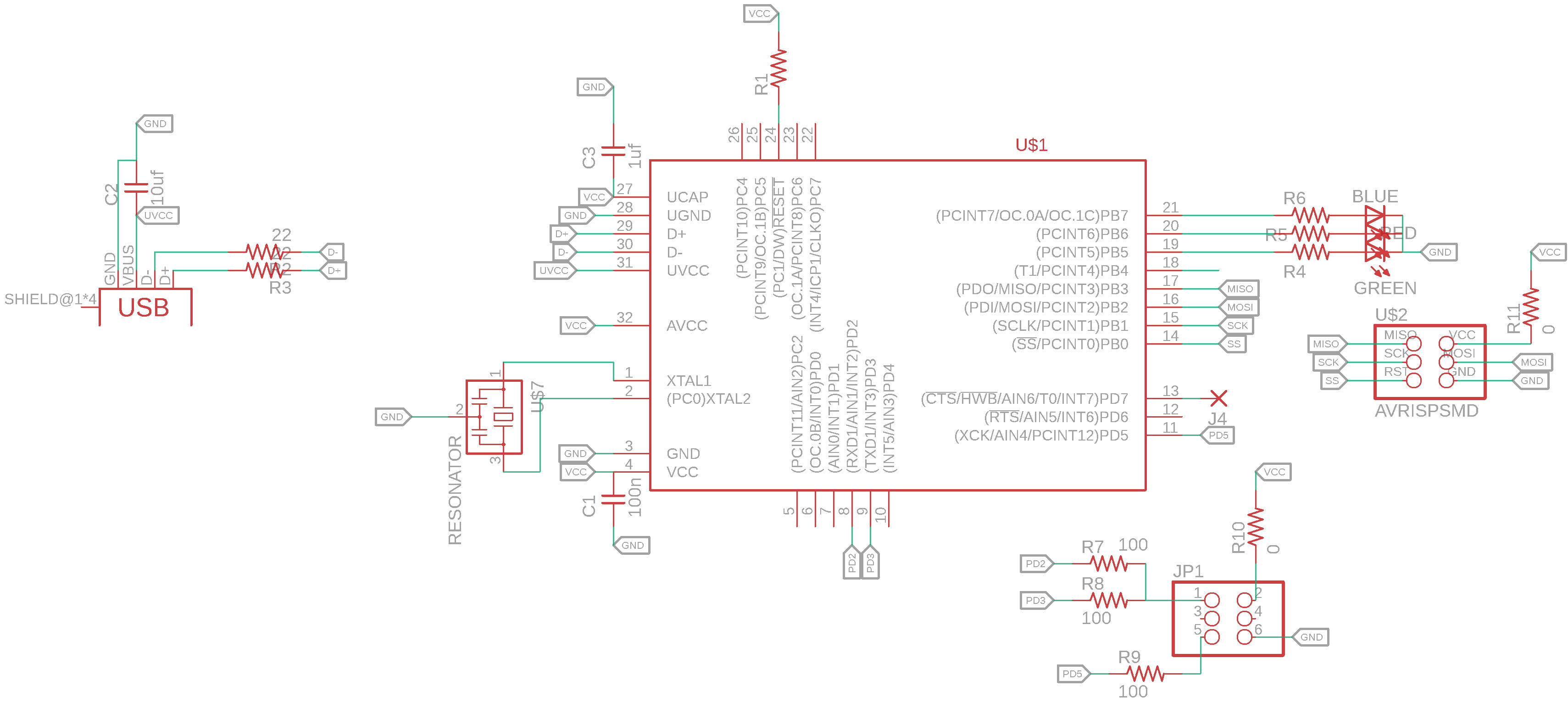
- here is the PCB schematic.
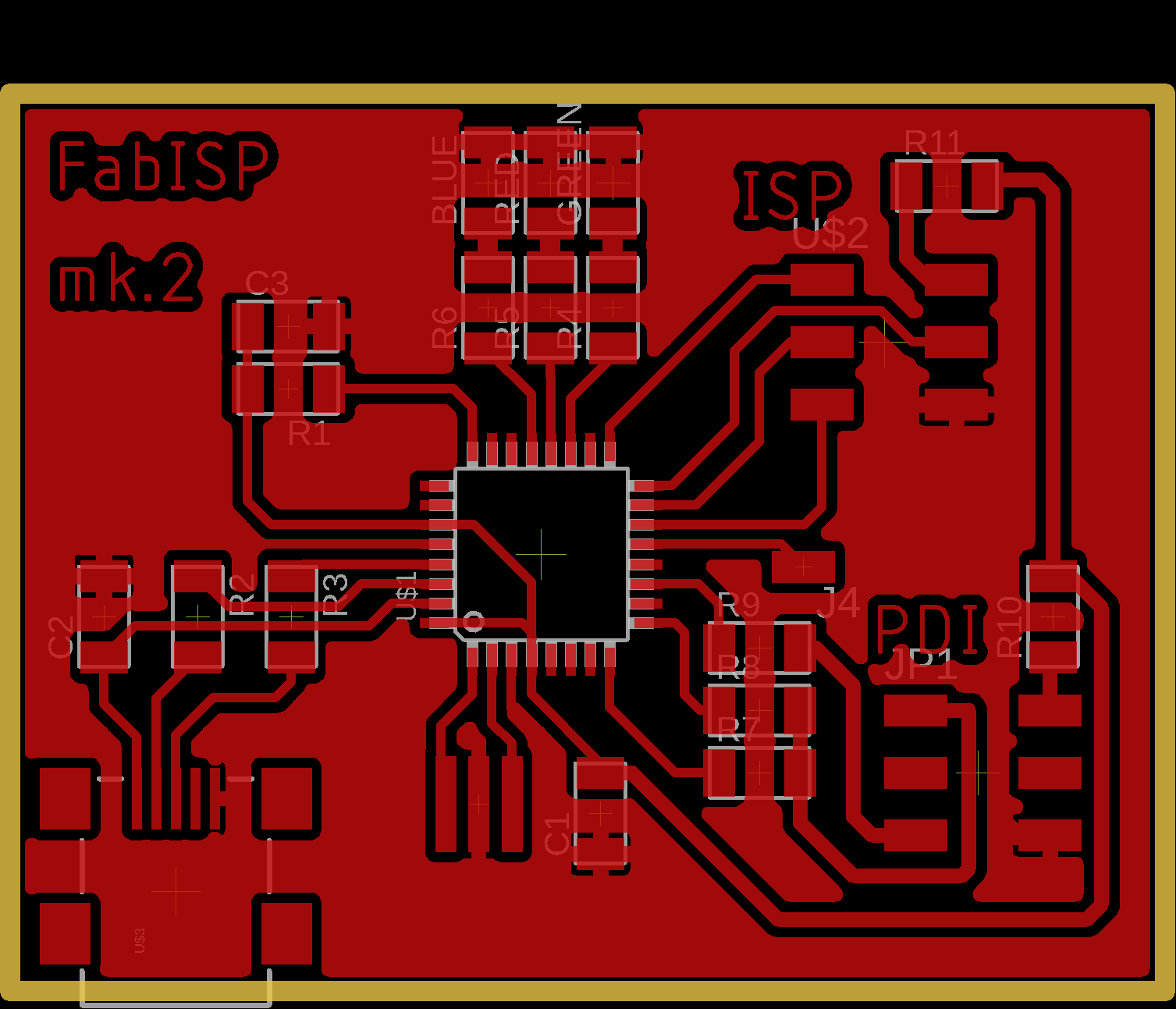
- Here is the PCB board route, I kept everything as it’s routed in the original project.
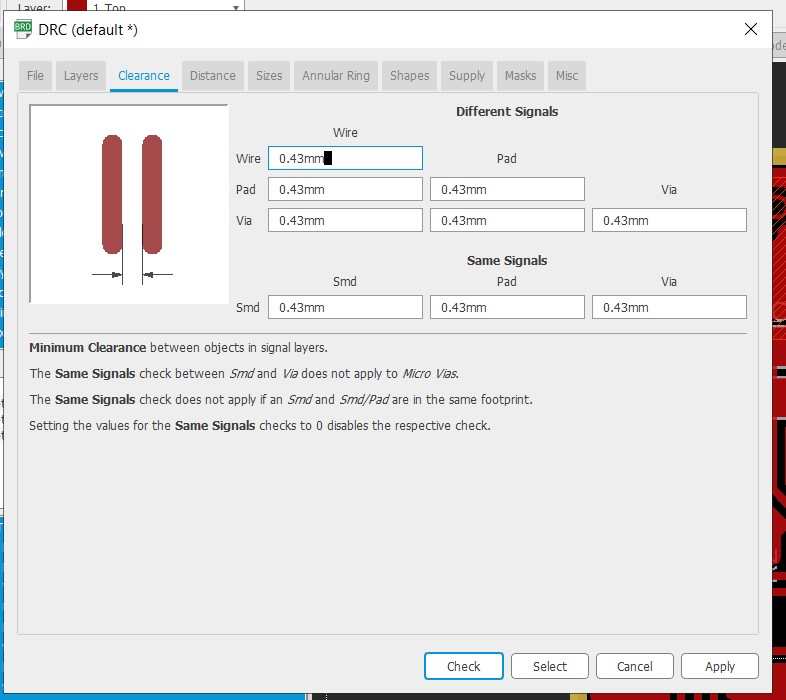
- Here are the design rules I used for routing the PCB, I like to put a clearance a little over the milling bit diameter, and for the trace width, our machine can get to about 0.2mm, but 0.35mm is enough for this board.

PCB Milling
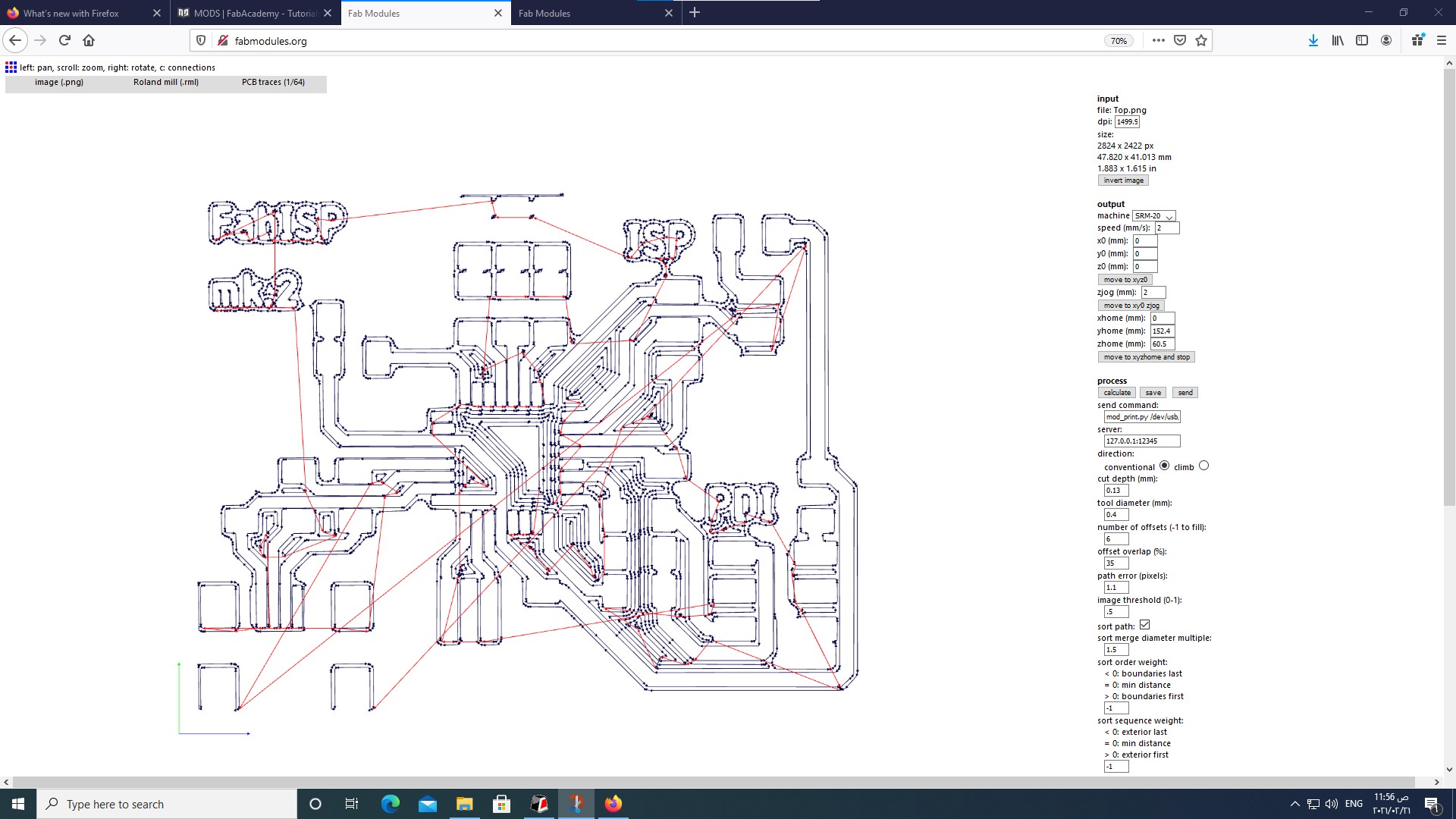
- Like in the first part of the assignment, after setting the machine zero, I made the Gcode using Fabmodules and started cutting.
- The first pause to check the milling was good this time, the machine is going through the copper layer, so I just resumed the job and let it continue getting back to it every while to check the milling process.

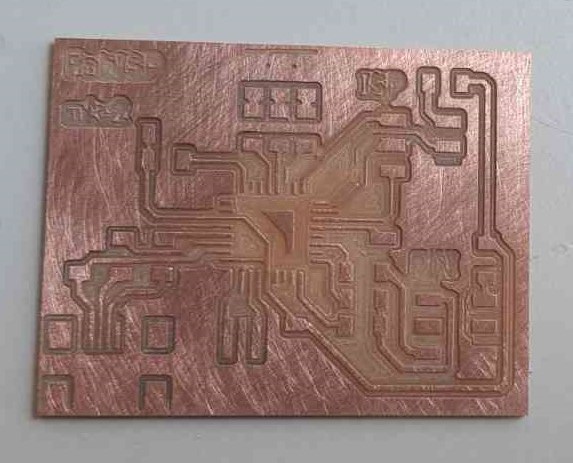
- Here is a photo after the milling is done, again I am using an old milling bit so the results are no the best.
- the PCB after light sanding.

- I did not show the cutting processes in the first part, so I am including it here. This is the endmill that I use to drill holes and cut the PCB layout. after replacing the endmill the Z-axis must but zero, and only the Z.
- Here is the cutting parametars in FabModules.

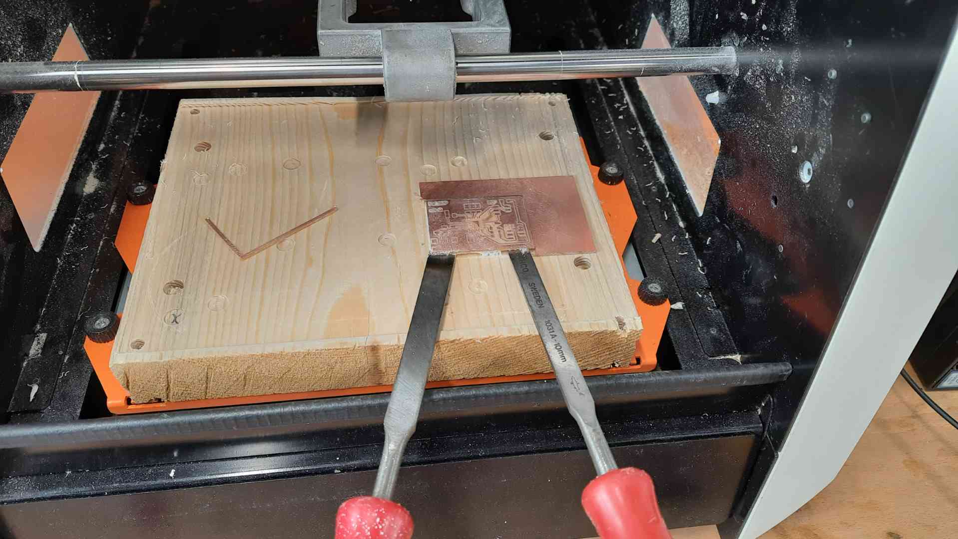
- the double-sided tape that we use is fairly strong, it holds the PCB well and prevents accidents, but it can be tricky to remove, I usually use 2 chisels and carefully pull it from two sides.
Milling using GERBER
A second methor to make a PCB is by using GERBER files, for more about this method take a look at my electronics design week assiegment
PCB post processing
- Now after the milling is done, I can slean the PCB more and remove any excess with a flat screwdriver.
-
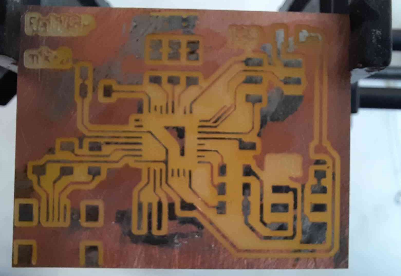
I like to apply a solder mask to the pads that will have components soldered on, it makes the soldering process much easier.
-
I start by applying a light layer of flux on the board and apply small amounts of solder to the solder pads.

- After that, I remove any excess with a solder wick.
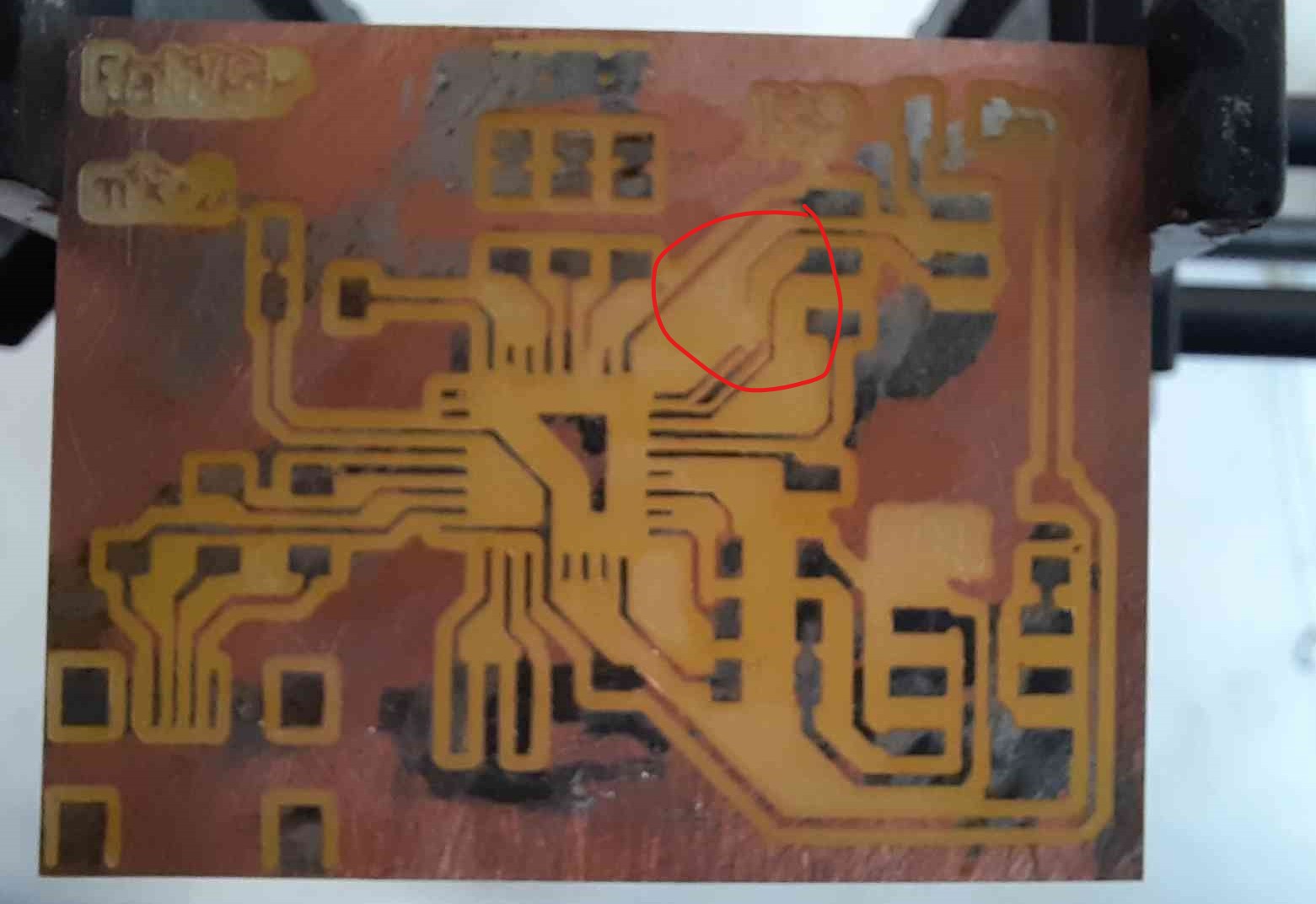
- I think the board turned out nicely, but I accidentally cut a trace, but it can be easily fixed with a small wire in soldering.
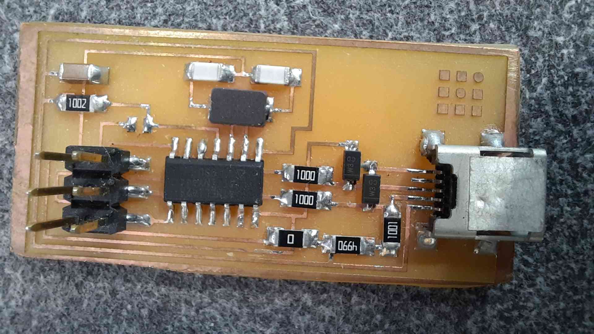
PCB soldering
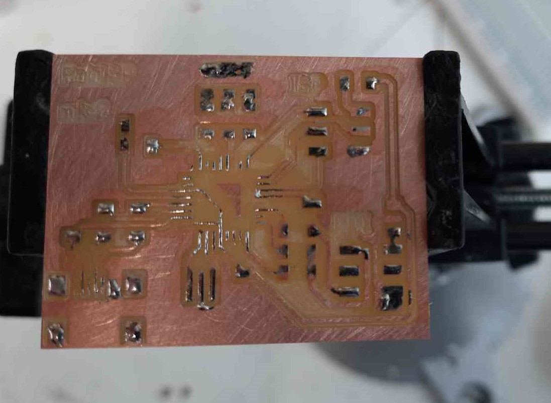
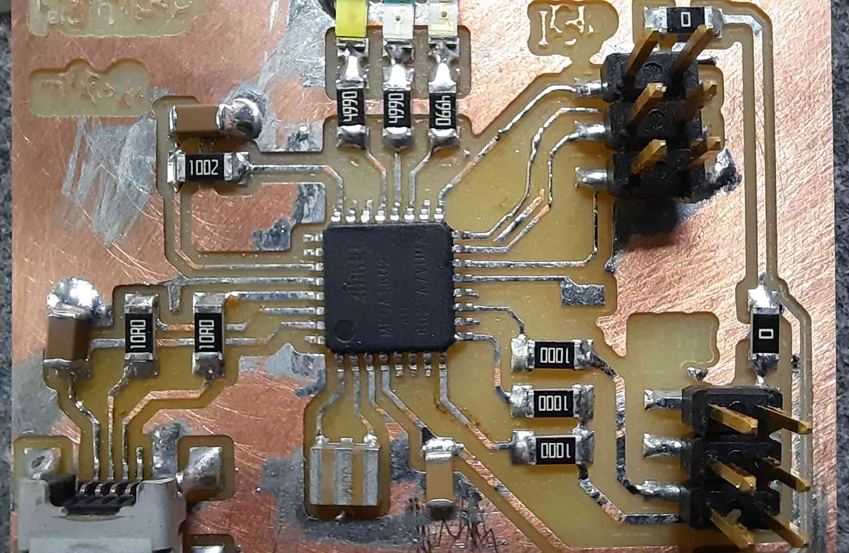
Here is the PCB after soldering and fixing the small issue that I had with the broken trace.
Programming
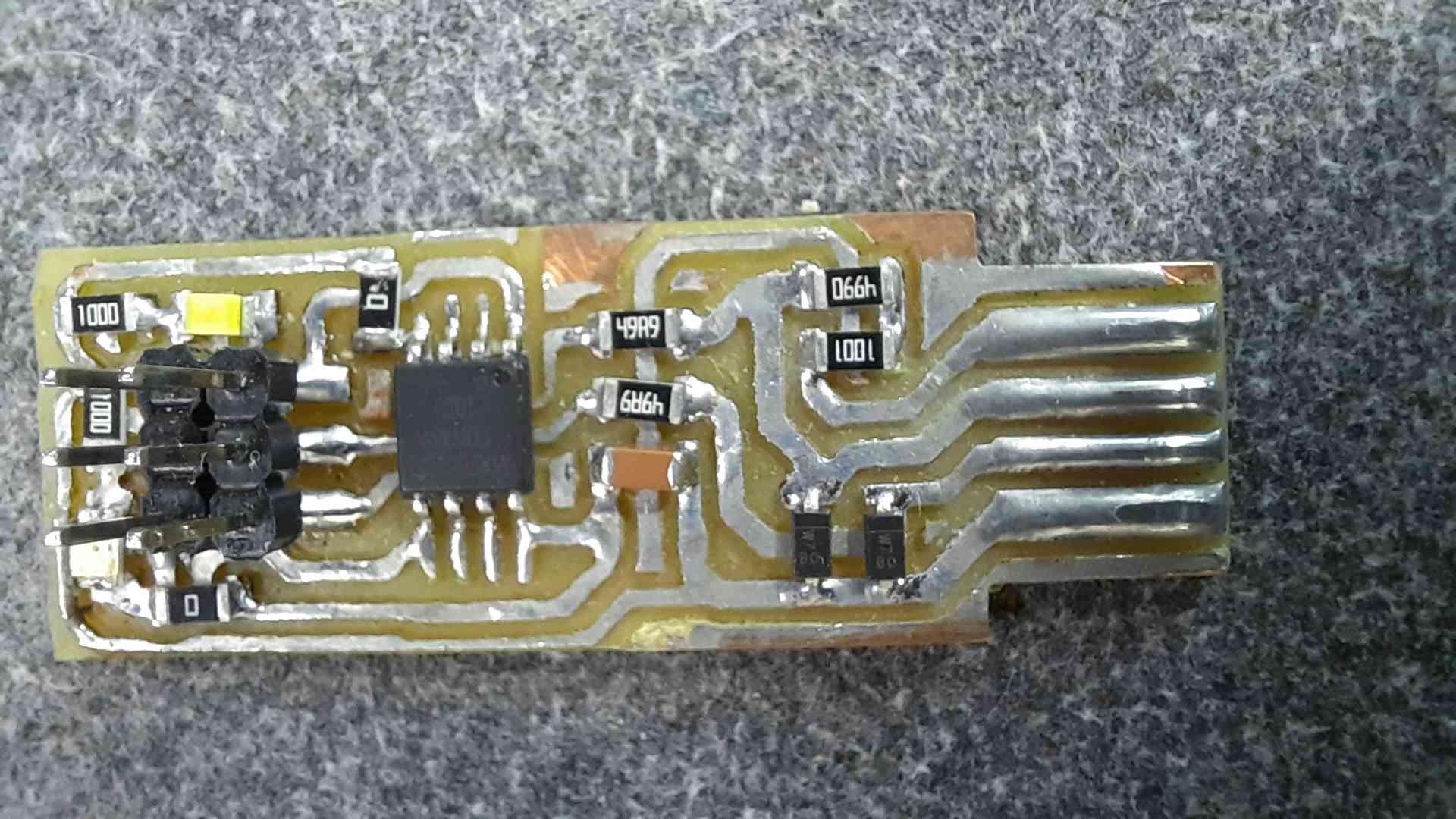
now that the board is ready, it should work once plugged in, but it did not. after some inspection I found that the data lines of the USB connector were not soldered correctly, so I fixed it and everything works from there.

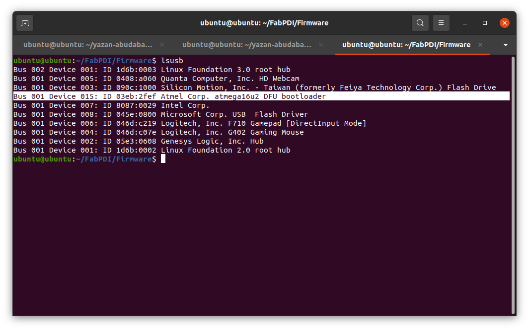
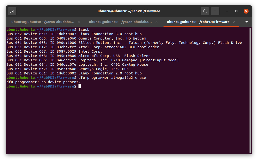
- In Linux Ubuntu, the comand
lsusbshould view the USB devices connected to the computer, if the board is correctly made it should show at atmega16u2 device.
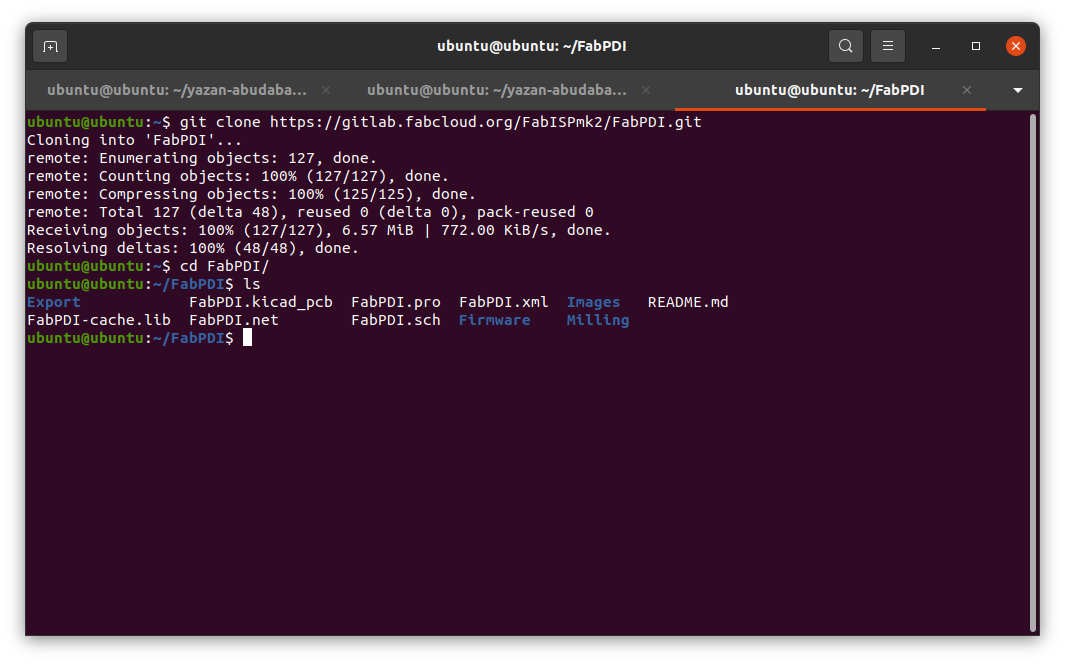
- Here I cloned the project to get the firmware using this command.
git clone <project link>
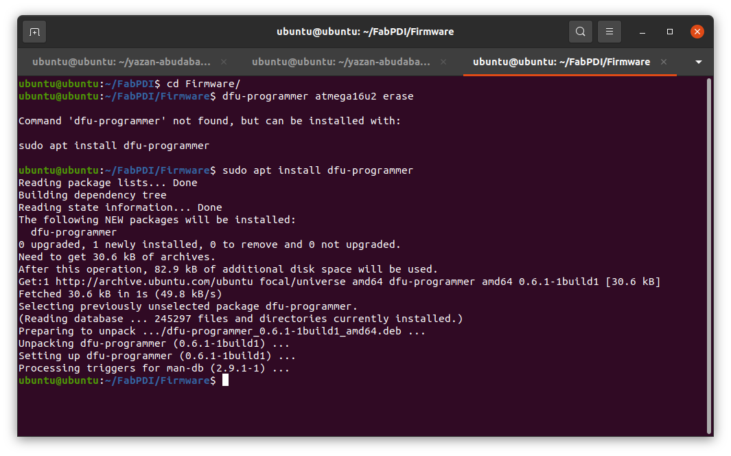
- from the project instructions the first command to perfome is:
dfu-programmer atmega16u2 erase
If the dfu-programmer software is not installed use in ubuntu;
sudo apt install dfu-programmer
- now after I installed the software it is not working though the device is connected as shown below.
-
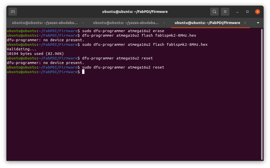
After some research, I found that I should use sudo with the dfu-programmer software to make it work.
-
I did try it again on another computer and it did work without sudo, still not sure where the issue is.
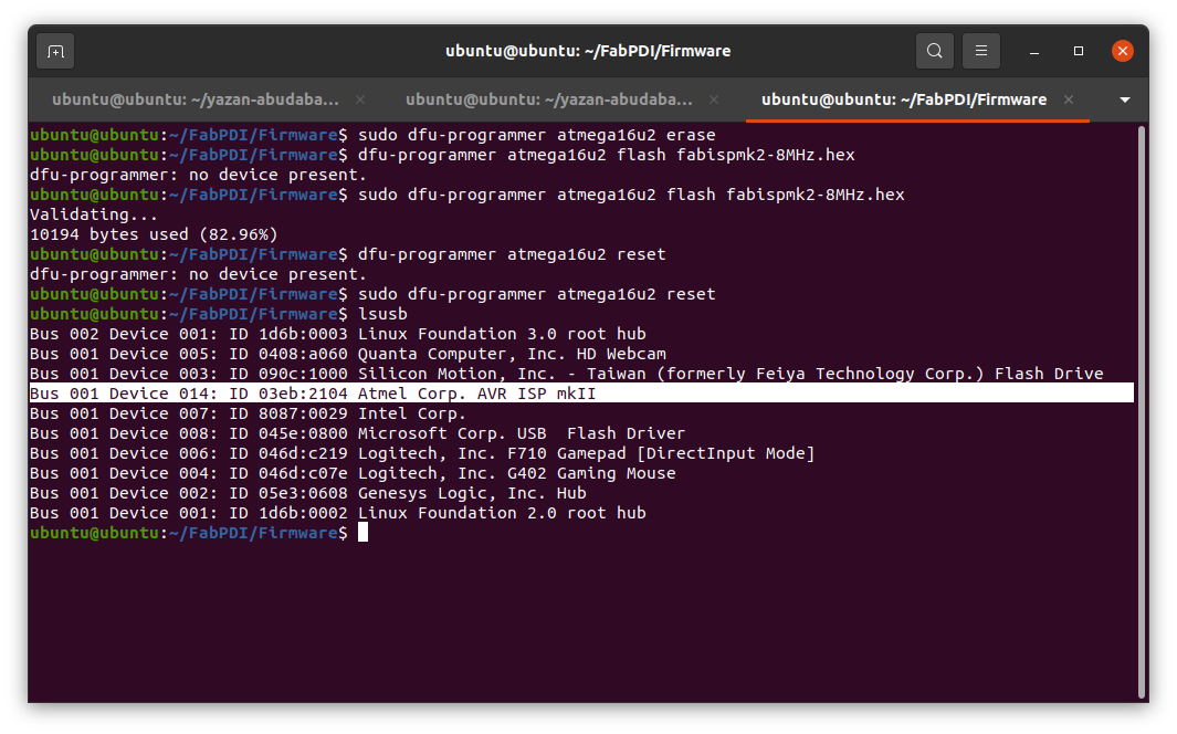
- after uploading the firmware the device is shown as AVRISPMKII.
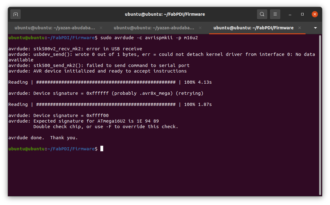
- I did not manage to get the test example from the end of the project to work.
after checking the Olimex AVR-ISP-MK2 open-source hardware board which this project is inspired.
I experimented with their firmware and tried their drivers in Windows 10, still no luck getting it to work with Arduino or avrdude.
I found this on their project page that might explain the issue.
*The hardware of your AVR-ISP-MK2 is fine. There is a software bug that affects LUFA-based programmers in newest releases of AVRDUDE. Either use AVRDUDE versions prior to 6.x.x or apply this patch to the AVRDUDE sources and compile.
The same problems appears in newest releases of Arduino IDE – they use AVRDUDE versions 6.0.1 or newer. The last suitable Arduino IDE version that uses pre-6.x.x AVRDUDE version is Arduino IDE 1.5.7.*
I did not know how to apply the patch, so I downloaded Arduino IDE 1.5.7 portable, and it did not work.
I kept getting this error
avrdude: usbdev_open(): did not find any USB device "usb"
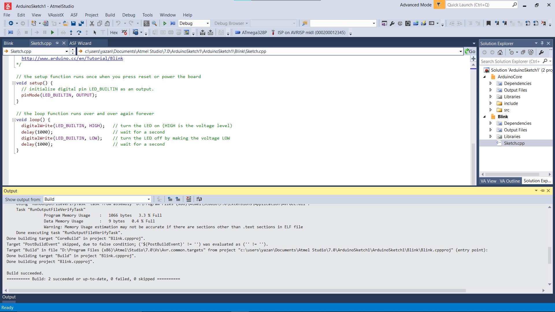
- I moved to Atmel studio to test the programmer, and it works!
Here I show in the interface settings that the software found the programmer, and when I connected it to an Arduino Uno board it managed to read its signature.

- To make sure It uploads, I made a blinking software and uploaded it to the Arduino Uno, and it works perfectly.
Here is a video from Embdded programming week using the FabPDI programmer.